EP0805962B1 - Détection de fuites par gaz témoin avec un contrôle de conductance par vide primaire ou pression de la connection intermediaire - Google Patents
Détection de fuites par gaz témoin avec un contrôle de conductance par vide primaire ou pression de la connection intermediaire Download PDFInfo
- Publication number
- EP0805962B1 EP0805962B1 EP95943181A EP95943181A EP0805962B1 EP 0805962 B1 EP0805962 B1 EP 0805962B1 EP 95943181 A EP95943181 A EP 95943181A EP 95943181 A EP95943181 A EP 95943181A EP 0805962 B1 EP0805962 B1 EP 0805962B1
- Authority
- EP
- European Patent Office
- Prior art keywords
- inlet
- pressure
- valve
- fore
- pump
- Prior art date
- Legal status (The legal status is an assumption and is not a legal conclusion. Google has not performed a legal analysis and makes no representation as to the accuracy of the status listed.)
- Expired - Lifetime
Links
Images
Classifications
-
- G—PHYSICS
- G01—MEASURING; TESTING
- G01M—TESTING STATIC OR DYNAMIC BALANCE OF MACHINES OR STRUCTURES; TESTING OF STRUCTURES OR APPARATUS, NOT OTHERWISE PROVIDED FOR
- G01M3/00—Investigating fluid-tightness of structures
- G01M3/02—Investigating fluid-tightness of structures by using fluid or vacuum
- G01M3/04—Investigating fluid-tightness of structures by using fluid or vacuum by detecting the presence of fluid at the leakage point
- G01M3/20—Investigating fluid-tightness of structures by using fluid or vacuum by detecting the presence of fluid at the leakage point using special tracer materials, e.g. dye, fluorescent material, radioactive material
- G01M3/202—Investigating fluid-tightness of structures by using fluid or vacuum by detecting the presence of fluid at the leakage point using special tracer materials, e.g. dye, fluorescent material, radioactive material using mass spectrometer detection systems
Definitions
- the invention relates to a method for operating a Test gas leak detector with a two-stage friction vacuum pump and a diaphragm vacuum pump as a backing pump.
- the invention also relates to a the execution of the operating procedure Leak detector.
- a test gas leak detector of the type concerned here is known from DE-A-31 24 205. It continues to be meanwhile known with a leak detector of this type two-step leak detection process to perform that out a gross leak detection and a subsequent one sensitive leak detection. As long as the pressure in the The inlet area of the leak detector is still relatively high , it remains the one leading to the intermediate connection Line valve closed. That from the The backing gas pump gets into the gas mixture Forevacuum side of the second friction pump stage. Is in this gas due to a relatively large leak in the test specimen test gas (e.g. helium) already exists, then it arrives this in counterflow through both friction pump stages to the detector and is registered. Is the examinee not grossly leaky, can be low enough Pressure in the inlet area of the leak detector the valve in the line leading to the intermediate connection is open be so that the leak detection with a higher sensitivity can be carried out.
- the test specimen test gas e.g. helium
- Friction vacuum pumps can only be operated with a backing pressure operated, the upper limit of a few (e.g. 5) mbar. Diaphragm vacuum pumps have one Final pressure, which is also of this order of magnitude. Operation of a friction vacuum pump with a diaphragm vacuum pump as a backing pump therefore requires that the diaphragm vacuum pump is operated in the vicinity of its final pressure becomes. As the pressure approaches however, the ultimate pressure is affected by the pumping speed of a diaphragm vacuum pump towards zero. Since the response time of a Leak detector of the type affected here largely from Pumping speed depends on the backing pump, it will be used a diaphragm vacuum pump as backing pump very long.
- the response time is the time between the entry of test gas into the inlet of the leak detector and the registration of the test gas in the detector passes. This flows through during the gross leak detection Test gas in counterflow both friction pump stages so that the response time is relatively long. After switching of the leak detector on the sensitive Leak detection, the test gas only flows through one friction pump stage in counterflow so that the response time shortened.
- the invention has for its object a leak detector of the species concerned here in such a way that leak detection despite the use of a diaphragm vacuum pump with shorter response times can.
- the invention allows the inlet of the leak detector very early on the throttled connecting line to connect to the intermediate connection, even if too at this point the pressure in the area of the inlet of the Leak detector is even larger than the maximum allowable Pressure between the two friction pump stages.
- the main advantage of this measure is that very early on compared to the diaphragm pump much higher pumping speed of the second friction pump stage is available, which is a substantial shortening the response time results.
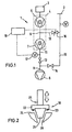
- the leak detector are general with 1, its inlet with 2, which acts as a mass spectrometer trained test gas detector with 3, the two-stage Friction vacuum pump with 4, the first as a turbomolecular pump trained friction pump stage with 5, the intermediate connection with 6, the second as a thread step scroll pump designed friction vacuum pump stage with 7 and the diaphragm pump used as backing pump with 8. Die Outlet side of the second friction pump stage 7 is with the inlet side 9 of the diaphragm pump 8 in connection, namely via line 11 with valve 12.
- the inlet 2 of the leak detector 1 is via the connecting line 13 with the valve 14 with the inlet side 9 of the diaphragm pump 8 in connection. Besides, can the connection between the inlet 2 of the leak detector 1 and the intermediate connection manufactured via line 15 with valve 16 become.
- the pressure measuring device 17 For monitoring the pressure in the area of the inlet side 9 of the diaphragm pump 8, the pressure measuring device 17 is provided. It delivers its signals to a controller (block 18). This is connected to the valve 16.
- test gas leak detector 1 For example, to perform a leak detection DUT at inlet 2 of test gas leak detector 1 connected. With valves 12 and 16 closed, it will pre-evacuated via line 13. With a sufficiently low one Pressure (approx. 5 mbar), the leak detection starts when the Valve 12. If there is a relatively large leak in the test object, test gas reaches the forevacuum side of the friction pump 4 and from there in counterflow to the detector 3. In this case the leak detection is ended.
- a sufficiently low one Pressure approximately 5 mbar
- valve 16 Since the conductance of valve 16 is adjustable, there is Possibility of connecting inlet 2 to the intermediate connection 6 can be opened at a time when the Inlet pressure is still higher than the necessary pressure on Intermediate connection 6.
- the conductance in the connecting line must be controlled so that the valve 16 each required pressure difference is maintained. With decreasing Pressure at inlet 2 increases the conductance of valve 16. It is fully open when the inlet pressure matches the pressure at Intermediate connection 6 corresponds.
- control described is expediently carried out automatically in Depending on the pressure at the intermediate inlet 6 or - how realized in the embodiment - depending on Forevacuum pressure, measured with the pressure measuring device 17. This delivers its signals to the controller 18, which is the conductance of the Valve 16 according to the desired pressure conditions regulates.
- FIG. 2 shows an embodiment of the controllable Valve 16.
- the adjustable valve stamp 21 includes one Valve plate 22 with a 0-ring 23. If the 0-ring 23 is located Seat 24, the valve 16 is closed.
- the valve plate 22 is equipped with a cone 25, depending on the position of the valve stem 21 more or less in the corresponding Valve opening 26 conical to cone 25 dips. The size of the free annular gap between the cone 25 and opening 26 can thereby be varied.
- controllable valve 16 is also the Use of two or more valves with orifices other conductance limits possible. It becomes dependent from the inlet pressure successively from one valve to the other switched to the larger master value.
Claims (2)
- Procédé de fonctionnement d'un dispositif de recherche des fuites, comportant une entrée (2), un détecteur (3) configuré en tant que spectromètre de masse, un premier étage de pompe à vide à friction (5), un deuxième étage de pompe à vide à friction (7), un raccord intermédiaire (6) entre le premier et le deuxième étage de pompe à vide à friction, une pompe à vide préalable (8) configurée en tant que pompe à vide à membrane, une première conduite de raccordement (13) pouvant être fermée entre l'entrée (2) du dispositif de recherche des fuites et le côté d'entrée (9) de la pompe à vide préalable (8), une deuxième conduite de raccordement (11) pouvant être fermée entre la sortie du deuxième étage de pompe à vide à friction (7) et le côté d'entrée (9) de la pompe à vide préalable (8), ainsi qu'une troisième conduite (15) réglable quant à sa conductance entre l'entrée (2) du dispositif de recherche des fuites et le raccord intermédiaire (6) ; pour mettre en application le procédé de recherche des fuites, un échantillon d'essai raccordé à l'entrée (2) est tout d'abord évacué par la conduite (13) jusqu'à environ 5 mbar ; une recherche grossière des fuites commence alors par l'ouverture de la soupape (12) ; si aucune fuite grossière n'est enregistrée, l'évacuation de l'échantillon d'essai par la conduite (13) se poursuit et la conduite de raccordement (15) équipée d'une soupape (16) réglable est ouverte pour débuter la recherche sensible des fuites ; la soupape (16) est réglée en fonction de la pression de vide préalable ou de la pression régnant au niveau de l'entrée intermédiaire (6), de telle sorte qu'une pression est maintenue entre les deux étages de pompe à vide à friction (5, 7), ladite pression étant d'une part la plus élevée possible et permettant d'autre part le maintien du vide de service dans le détecteur (3).
- Dispositif de recherche des fuites convenant pour la mise oeuvre du procédé de fonctionnement selon la revendication 1, comportant une entrée (2), un détecteur (3) configuré en tant que spectromètre de masse, un premier étage de pompe à vide à friction (5), un deuxième étage de pompe à vide à friction (7), un raccord intermédiaire (6) entre le premier et le deuxième étage de pompe à vide à friction, une pompe à vide préalable (8) configurée en tant que pompe à vide à membrane, une première conduite de raccordement (13) pouvant être fermée entre l'entrée (2) du dispositif de recherche des fuites et le côté entrée (9) de la pompe à vide préalable (8), une deuxième conduite de raccordement (11) pouvant être fermée entre la sortie du deuxième niveau de la pompe à vide à friction (7) et le côté entrée (9) de la pompe à vide préalable (8), ainsi qu'une troisième conduite (15) entre l'entrée (2) du dispositif de recherche des fuites et le raccord intermédiaire (6), la conductance de la troisième conduite (15) étant réglée en fonction de la pression de vide préalable ou de la pression régnant au niveau de l'entrée intermédiaire (6), et une soupape (16) étant équipée d'un piston de soupape (21) pour le réglage de la conductance, ledit piston de soupape portant une cône (25) auquel est associée une ouverture de soupape (26) d'une forme conique correspondante, ou bien plusieurs soupapes étant prévues pour le réglage de la conductance.
Applications Claiming Priority (3)
| Application Number | Priority Date | Filing Date | Title |
|---|---|---|---|
| DE19504278A DE19504278A1 (de) | 1995-02-09 | 1995-02-09 | Testgas-Lecksuchgerät |
| DE19504278 | 1995-02-09 | ||
| PCT/EP1995/005079 WO1996024828A1 (fr) | 1995-02-09 | 1995-12-21 | Appareil de detection de fuites par gaz temoin |
Publications (2)
| Publication Number | Publication Date |
|---|---|
| EP0805962A1 EP0805962A1 (fr) | 1997-11-12 |
| EP0805962B1 true EP0805962B1 (fr) | 2003-10-29 |
Family
ID=7753554
Family Applications (1)
| Application Number | Title | Priority Date | Filing Date |
|---|---|---|---|
| EP95943181A Expired - Lifetime EP0805962B1 (fr) | 1995-02-09 | 1995-12-21 | Détection de fuites par gaz témoin avec un contrôle de conductance par vide primaire ou pression de la connection intermediaire |
Country Status (7)
| Country | Link |
|---|---|
| US (1) | US5900537A (fr) |
| EP (1) | EP0805962B1 (fr) |
| JP (1) | JP3483571B2 (fr) |
| KR (1) | KR100392540B1 (fr) |
| CN (1) | CN1119642C (fr) |
| DE (2) | DE19504278A1 (fr) |
| WO (1) | WO1996024828A1 (fr) |
Families Citing this family (26)
| Publication number | Priority date | Publication date | Assignee | Title |
|---|---|---|---|---|
| DE19638506A1 (de) * | 1996-09-20 | 1998-03-26 | Leybold Vakuum Gmbh | Verfahren zur Untersuchung einer Mehrzahl ähnlicher Prüflinge auf Lecks sowie für die Durchführung dieses Verfahrens geeigneter Lecksucher |
| FR2761776B1 (fr) * | 1997-04-03 | 1999-07-23 | Alsthom Cge Alcatel | Detecteur de fuite a gaz traceur |
| DE19735250A1 (de) * | 1997-08-14 | 1999-02-18 | Leybold Vakuum Gmbh | Verfahren zum Betrieb eines Heliumlecksuchers und für die Durchführung dieses Verfahrens geeigneter Heliumlecksucher |
| JP3038432B2 (ja) * | 1998-07-21 | 2000-05-08 | セイコー精機株式会社 | 真空ポンプ及び真空装置 |
| FR2787192B1 (fr) * | 1998-12-10 | 2001-01-05 | Cit Alcatel | Vitesse variable sur le pompage primaire d'un detecteur de fuites par gaz traceur |
| DE10156205A1 (de) * | 2001-11-15 | 2003-06-05 | Inficon Gmbh | Testgaslecksuchgerät |
| DE10302987A1 (de) * | 2003-01-25 | 2004-08-05 | Inficon Gmbh | Lecksuchgerät mit einem Einlass |
| DE10319633A1 (de) * | 2003-05-02 | 2004-11-18 | Inficon Gmbh | Lecksuchgerät |
| DE10324596A1 (de) | 2003-05-30 | 2004-12-16 | Inficon Gmbh | Lecksuchgerät |
| DE602004013612D1 (de) * | 2003-09-26 | 2008-06-19 | Edwards Ltd | Erfassung von verunreinigungen in einem durch eine vakuumpumpe gepumpten fluid |
| DE102005009713A1 (de) * | 2005-03-03 | 2006-09-07 | Inficon Gmbh | Lecksuchgerät mit Schnüffelsonde |
| US7472581B2 (en) * | 2005-03-16 | 2009-01-06 | Tokyo Electron Limited | Vacuum apparatus |
| DE102005043494A1 (de) * | 2005-09-13 | 2007-03-15 | Inficon Gmbh | Lecksuchgerät mit Schnüffelsonde |
| US7459677B2 (en) * | 2006-02-15 | 2008-12-02 | Varian, Inc. | Mass spectrometer for trace gas leak detection with suppression of undesired ions |
| CN100592078C (zh) * | 2006-10-23 | 2010-02-24 | 福建赛特新材料有限公司 | 用于真空绝热板的阻隔薄膜漏率检测方法 |
| KR200457714Y1 (ko) | 2008-05-26 | 2012-01-02 | 주식회사인스타 | 가스압력 측정 및 누설 시험기 |
| CN101710017B (zh) * | 2009-12-17 | 2011-02-16 | 中国航天科技集团公司第五研究院第五一○研究所 | 一种真空系统检漏的方法 |
| JP5948349B2 (ja) * | 2011-02-03 | 2016-07-06 | オーリコン レイボルド バキューム ゲーエムベーハー | 漏れ検出デバイス |
| DE102011107334B4 (de) * | 2011-07-14 | 2023-03-16 | Leybold Gmbh | Lecksucheinrichtung sowie Verfahren zum Überprüfen von Gegenständen auf Dichtigkeit mittels einer Lecksucheinrichtung |
| DE102013218506A1 (de) * | 2013-09-16 | 2015-03-19 | Inficon Gmbh | Schnüffellecksucher mit mehrstufiger Membranpumpe |
| DE102015222213A1 (de) * | 2015-11-11 | 2017-05-11 | Inficon Gmbh | Druckmessung am Prüfgaseinlass |
| CN105784289A (zh) * | 2016-04-12 | 2016-07-20 | 上海理工大学 | 判断冻干机内硅油泄漏和一次升华干燥结束点的方法 |
| DE102016210701A1 (de) * | 2016-06-15 | 2017-12-21 | Inficon Gmbh | Massenspektrometrischer Lecksucher mit Turbomolekularpumpe und Boosterpumpe auf gemeinsamer Welle |
| FR3070489B1 (fr) * | 2017-08-29 | 2020-10-23 | Pfeiffer Vacuum | Detecteur de fuites et procede de detection de fuites pour le controle de l'etancheite d'objets a tester |
| FR3072774B1 (fr) * | 2017-10-19 | 2019-11-15 | Pfeiffer Vacuum | Detecteur de fuites pour le controle de l'etancheite d'un objet a tester |
| CN112557606B (zh) * | 2021-02-28 | 2021-06-04 | 中国工程物理研究院核物理与化学研究所 | 一种专用于气体探测器性能参数测定的辅助装置 |
Citations (1)
| Publication number | Priority date | Publication date | Assignee | Title |
|---|---|---|---|---|
| WO1993012411A1 (fr) * | 1991-12-07 | 1993-06-24 | Leybold Aktiengesellschaft | Detecteur de fuites pour installations a vide, et procede de recherche de fuites dans des installations a vide |
Family Cites Families (8)
| Publication number | Priority date | Publication date | Assignee | Title |
|---|---|---|---|---|
| US3699779A (en) * | 1971-06-01 | 1972-10-24 | Ralph C Schlichtig | Thermally powered diaphragm pump system for heat transfer |
| FR2475728A1 (fr) * | 1980-02-11 | 1981-08-14 | Cit Alcatel | Detecteur de fuites a helium |
| DE3124205A1 (de) * | 1981-06-19 | 1982-12-30 | Balzers Hochvakuum Gmbh, 6200 Wiesbaden | Lecksuchanordnung |
| DE3775213D1 (de) * | 1987-03-27 | 1992-01-23 | Leybold Ag | Lecksuchgeraet und betriebsverfahren dazu. |
| US4893497A (en) * | 1988-09-12 | 1990-01-16 | Philip Danielson | Leak detection system |
| FR2681688B1 (fr) * | 1991-09-24 | 1993-11-19 | Alcatel Cit | Installation de detection de fuites de gaz utilisant la technique de reniflage. |
| FR2681689B1 (fr) * | 1991-09-25 | 1993-11-12 | Alcatel Cit | Detecteur de fuite a gaz traceur. |
| DE4410656A1 (de) * | 1994-03-26 | 1995-09-28 | Balzers Pfeiffer Gmbh | Reibungspumpe |
-
1995
- 1995-02-09 DE DE19504278A patent/DE19504278A1/de not_active Ceased
- 1995-12-21 US US08/875,370 patent/US5900537A/en not_active Expired - Lifetime
- 1995-12-21 JP JP52391996A patent/JP3483571B2/ja not_active Expired - Fee Related
- 1995-12-21 WO PCT/EP1995/005079 patent/WO1996024828A1/fr active IP Right Grant
- 1995-12-21 DE DE59510816T patent/DE59510816D1/de not_active Expired - Lifetime
- 1995-12-21 EP EP95943181A patent/EP0805962B1/fr not_active Expired - Lifetime
- 1995-12-21 KR KR1019970705414A patent/KR100392540B1/ko not_active IP Right Cessation
-
1996
- 1996-02-08 CN CN96101379A patent/CN1119642C/zh not_active Expired - Lifetime
Patent Citations (1)
| Publication number | Priority date | Publication date | Assignee | Title |
|---|---|---|---|---|
| WO1993012411A1 (fr) * | 1991-12-07 | 1993-06-24 | Leybold Aktiengesellschaft | Detecteur de fuites pour installations a vide, et procede de recherche de fuites dans des installations a vide |
Also Published As
| Publication number | Publication date |
|---|---|
| WO1996024828A1 (fr) | 1996-08-15 |
| CN1146553A (zh) | 1997-04-02 |
| JPH10513561A (ja) | 1998-12-22 |
| CN1119642C (zh) | 2003-08-27 |
| US5900537A (en) | 1999-05-04 |
| EP0805962A1 (fr) | 1997-11-12 |
| KR19980702019A (ko) | 1998-07-15 |
| DE59510816D1 (de) | 2003-12-04 |
| DE19504278A1 (de) | 1996-08-14 |
| KR100392540B1 (ko) | 2003-10-22 |
| JP3483571B2 (ja) | 2004-01-06 |
Similar Documents
| Publication | Publication Date | Title |
|---|---|---|
| EP0805962B1 (fr) | Détection de fuites par gaz témoin avec un contrôle de conductance par vide primaire ou pression de la connection intermediaire | |
| EP0283543B1 (fr) | Appareil de détection de fuites et son fonctionnement | |
| EP0615615B1 (fr) | Detecteur de fuites pour installations a vide, et procede de recherche de fuites dans des installations a vide | |
| EP0793802B1 (fr) | Dispositif de detection de fuites pourvu de pompes a vide et procede permettant son fonctionnement | |
| EP0432305B1 (fr) | Procédé et dispositif de contrôle d'étanchéité | |
| CH640311A5 (de) | Verfahren und vorrichtung zur evakuierung eines rezipienten. | |
| EP3374746B1 (fr) | Mesure de pression à l'orifice d'entrée de gaz | |
| EP1004011B1 (fr) | Procede de fonctionnement d'un dispositif de detection de fuites d'helium et dispositif de detection adapte pour la mise en oeuvre dudit procede | |
| EP2601498B1 (fr) | Détecteur de fuites | |
| EP0242684B1 (fr) | Appareil de détection de fuites avec détecteur et fuite de test | |
| EP1119752A1 (fr) | Detecteur de fuites pelliculaire | |
| EP1444495A1 (fr) | Detecteur de fuite de gaz traceur | |
| WO2004097363A2 (fr) | Appareil de detection de fuites | |
| EP0834061A1 (fr) | Appareil de detection de fuite dote d'une pompe a previde | |
| EP1629263B1 (fr) | Appareil de detection de fuite | |
| EP0927345A1 (fr) | Procede pour realiser un essai d'etancheite sur une pluralite d'eprouvettes semblables et detecteur de fuites permettant la mise en oeuvre de ce procede | |
| EP0487919B1 (fr) | Appareil détecteur de fuites | |
| DE102014223841A1 (de) | Vorrichtung und Verfahren zur Gegenstrom-Leckdetektion | |
| DE102022115562A1 (de) | Verfahren zur Messung der Umgebungskonzentration eines leichten Gases mit einer massenspektrometrischen Gegenstrom-Lecksuchvorrichtung | |
| DD205995B1 (de) | Vorrichtung zur integralen vakuum-lenkratenmessung | |
| DD253874A1 (de) | Verfahren zum betrieb einer leckpruefeinrichtung | |
| DD257878A1 (de) | Verfahren zur auswertung von drucksignalen einer vakuumtechnischen dichtpruefanlage | |
| DE102021115664A1 (de) | Leckdetektoren | |
| DE1773646A1 (de) | Verfahren und Vorrichtung zur Erhoehung der Empfindlichkeit und zur Vereinfachung der Arbeitsweise bei Massenspektrometern | |
| DE19853368A1 (de) | Verfahren und Vorrichtung zur Messung der Wassermenge und Leckage in Behältern |
Legal Events
| Date | Code | Title | Description |
|---|---|---|---|
| PUAI | Public reference made under article 153(3) epc to a published international application that has entered the european phase |
Free format text: ORIGINAL CODE: 0009012 |
|
| 17P | Request for examination filed |
Effective date: 19970507 |
|
| AK | Designated contracting states |
Kind code of ref document: A1 Designated state(s): DE FR GB IT |
|
| 17Q | First examination report despatched |
Effective date: 19991116 |
|
| GRAH | Despatch of communication of intention to grant a patent |
Free format text: ORIGINAL CODE: EPIDOS IGRA |
|
| RTI1 | Title (correction) |
Free format text: TEST GAS LEAKAGE DETECTION WITH CONDUCTANCE CONTROL OF PRIMARY VACUUM PRESSURE OR INTERMEDIATE CONNECTION PRESSURE |
|
| GRAS | Grant fee paid |
Free format text: ORIGINAL CODE: EPIDOSNIGR3 |
|
| GRAA | (expected) grant |
Free format text: ORIGINAL CODE: 0009210 |
|
| AK | Designated contracting states |
Kind code of ref document: B1 Designated state(s): DE FR GB IT |
|
| PG25 | Lapsed in a contracting state [announced via postgrant information from national office to epo] |
Ref country code: IT Free format text: LAPSE BECAUSE OF FAILURE TO SUBMIT A TRANSLATION OF THE DESCRIPTION OR TO PAY THE FEE WITHIN THE PRE;WARNING: LAPSES OF ITALIAN PATENTS WITH EFFECTIVE DATE BEFORE 2007 MAY HAVE OCCURRED AT ANY TIME BEFORE 2007. THE CORRECT EFFECTIVE DATE MAY BE DIFFERENT FROM THE ONE RECORDED.SCRIBED TIME-LIMIT Effective date: 20031029 |
|
| REG | Reference to a national code |
Ref country code: GB Ref legal event code: FG4D Free format text: NOT ENGLISH |
|
| REF | Corresponds to: |
Ref document number: 59510816 Country of ref document: DE Date of ref document: 20031204 Kind code of ref document: P |
|
| RAP2 | Party data changed (patent owner data changed or rights of a patent transferred) |
Owner name: LEYBOLD VAKUUM GMBH |
|
| GBT | Gb: translation of ep patent filed (gb section 77(6)(a)/1977) |
Effective date: 20040106 |
|
| REG | Reference to a national code |
Ref country code: GB Ref legal event code: FG4C Free format text: NOTIFICATION HAS NOW BEEN RECEIVED FROM THE EUROPEAN PATENT OFFICE THAT THE CORRECT NAME OF THE PROPRIETOR IS: LEYBOLD VAKUUM GMBH THIS CORRECTION WAS PUBLISHED IN EUROPEAN PATENT BULLETIN 04/02 OF 20040107. |
|
| ET | Fr: translation filed | ||
| PLBE | No opposition filed within time limit |
Free format text: ORIGINAL CODE: 0009261 |
|
| STAA | Information on the status of an ep patent application or granted ep patent |
Free format text: STATUS: NO OPPOSITION FILED WITHIN TIME LIMIT |
|
| RAP2 | Party data changed (patent owner data changed or rights of a patent transferred) |
Owner name: LEYBOLD VACUUM GMBH |
|
| 26N | No opposition filed |
Effective date: 20040730 |
|
| PGFP | Annual fee paid to national office [announced via postgrant information from national office to epo] |
Ref country code: GB Payment date: 20101221 Year of fee payment: 16 |
|
| GBPC | Gb: european patent ceased through non-payment of renewal fee |
Effective date: 20121221 |
|
| PG25 | Lapsed in a contracting state [announced via postgrant information from national office to epo] |
Ref country code: GB Free format text: LAPSE BECAUSE OF NON-PAYMENT OF DUE FEES Effective date: 20121221 |
|
| PGFP | Annual fee paid to national office [announced via postgrant information from national office to epo] |
Ref country code: FR Payment date: 20141212 Year of fee payment: 20 |
|
| PGFP | Annual fee paid to national office [announced via postgrant information from national office to epo] |
Ref country code: DE Payment date: 20141222 Year of fee payment: 20 |
|
| REG | Reference to a national code |
Ref country code: DE Ref legal event code: R071 Ref document number: 59510816 Country of ref document: DE |