EP0805744B1 - Hot melt fluidized cladding of innerduct liner - Google Patents
Hot melt fluidized cladding of innerduct liner Download PDFInfo
- Publication number
- EP0805744B1 EP0805744B1 EP96905340A EP96905340A EP0805744B1 EP 0805744 B1 EP0805744 B1 EP 0805744B1 EP 96905340 A EP96905340 A EP 96905340A EP 96905340 A EP96905340 A EP 96905340A EP 0805744 B1 EP0805744 B1 EP 0805744B1
- Authority
- EP
- European Patent Office
- Prior art keywords
- innerduct
- conduit
- anyone
- polymeric material
- liner
- Prior art date
- Legal status (The legal status is an assumption and is not a legal conclusion. Google has not performed a legal analysis and makes no representation as to the accuracy of the status listed.)
- Expired - Lifetime
Links
- 238000005253 cladding Methods 0.000 title claims abstract description 5
- 239000012943 hotmelt Substances 0.000 title abstract description 9
- 239000000463 material Substances 0.000 claims abstract description 45
- 238000000034 method Methods 0.000 claims description 45
- 238000001125 extrusion Methods 0.000 claims description 14
- 229920000642 polymer Polymers 0.000 claims description 11
- 239000011248 coating agent Substances 0.000 claims description 10
- 238000000576 coating method Methods 0.000 claims description 10
- -1 polyethylene Polymers 0.000 claims description 10
- 238000000151 deposition Methods 0.000 claims description 7
- 239000004810 polytetrafluoroethylene Substances 0.000 claims description 5
- 229920001343 polytetrafluoroethylene Polymers 0.000 claims description 5
- 239000000843 powder Substances 0.000 claims description 5
- 239000002033 PVDF binder Substances 0.000 claims description 4
- 239000004698 Polyethylene Substances 0.000 claims description 4
- 239000000203 mixture Substances 0.000 claims description 4
- 229920000573 polyethylene Polymers 0.000 claims description 4
- 229920002981 polyvinylidene fluoride Polymers 0.000 claims description 4
- OKTJSMMVPCPJKN-UHFFFAOYSA-N Carbon Chemical compound [C] OKTJSMMVPCPJKN-UHFFFAOYSA-N 0.000 claims description 3
- 239000010439 graphite Substances 0.000 claims description 3
- 229910002804 graphite Inorganic materials 0.000 claims description 3
- 238000002844 melting Methods 0.000 claims description 3
- 230000008018 melting Effects 0.000 claims description 3
- 238000005507 spraying Methods 0.000 claims description 3
- 238000010438 heat treatment Methods 0.000 claims description 2
- 229920002545 silicone oil Polymers 0.000 claims description 2
- 229920001169 thermoplastic Polymers 0.000 claims description 2
- VYPSYNLAJGMNEJ-UHFFFAOYSA-N Silicium dioxide Chemical compound O=[Si]=O VYPSYNLAJGMNEJ-UHFFFAOYSA-N 0.000 claims 2
- 238000002156 mixing Methods 0.000 claims 1
- 239000000377 silicon dioxide Substances 0.000 claims 1
- 239000000454 talc Substances 0.000 claims 1
- 229910052623 talc Inorganic materials 0.000 claims 1
- 230000008021 deposition Effects 0.000 abstract description 6
- 239000000654 additive Substances 0.000 abstract description 2
- 230000000996 additive effect Effects 0.000 abstract 1
- 239000007921 spray Substances 0.000 description 14
- 239000000945 filler Substances 0.000 description 5
- 239000003795 chemical substances by application Substances 0.000 description 3
- 230000001050 lubricating effect Effects 0.000 description 3
- 239000000835 fiber Substances 0.000 description 2
- 239000000314 lubricant Substances 0.000 description 2
- 238000005461 lubrication Methods 0.000 description 2
- 239000004743 Polypropylene Substances 0.000 description 1
- 230000003466 anti-cipated effect Effects 0.000 description 1
- 238000000889 atomisation Methods 0.000 description 1
- 230000003247 decreasing effect Effects 0.000 description 1
- 238000005137 deposition process Methods 0.000 description 1
- 230000000694 effects Effects 0.000 description 1
- 239000002783 friction material Substances 0.000 description 1
- 230000004927 fusion Effects 0.000 description 1
- 238000000227 grinding Methods 0.000 description 1
- 238000004519 manufacturing process Methods 0.000 description 1
- 239000000289 melt material Substances 0.000 description 1
- 238000012986 modification Methods 0.000 description 1
- 230000004048 modification Effects 0.000 description 1
- 239000000049 pigment Substances 0.000 description 1
- 238000010094 polymer processing Methods 0.000 description 1
- 229920001155 polypropylene Polymers 0.000 description 1
- 230000001012 protector Effects 0.000 description 1
- 239000003381 stabilizer Substances 0.000 description 1
Images
Classifications
-
- F—MECHANICAL ENGINEERING; LIGHTING; HEATING; WEAPONS; BLASTING
- F16—ENGINEERING ELEMENTS AND UNITS; GENERAL MEASURES FOR PRODUCING AND MAINTAINING EFFECTIVE FUNCTIONING OF MACHINES OR INSTALLATIONS; THERMAL INSULATION IN GENERAL
- F16L—PIPES; JOINTS OR FITTINGS FOR PIPES; SUPPORTS FOR PIPES, CABLES OR PROTECTIVE TUBING; MEANS FOR THERMAL INSULATION IN GENERAL
- F16L58/00—Protection of pipes or pipe fittings against corrosion or incrustation
- F16L58/02—Protection of pipes or pipe fittings against corrosion or incrustation by means of internal or external coatings
- F16L58/04—Coatings characterised by the materials used
- F16L58/10—Coatings characterised by the materials used by rubber or plastics
- F16L58/1009—Coatings characterised by the materials used by rubber or plastics the coating being placed inside the pipe
- F16L58/1027—Coatings characterised by the materials used by rubber or plastics the coating being placed inside the pipe the coating being a sprayed layer
-
- B—PERFORMING OPERATIONS; TRANSPORTING
- B05—SPRAYING OR ATOMISING IN GENERAL; APPLYING FLUENT MATERIALS TO SURFACES, IN GENERAL
- B05D—PROCESSES FOR APPLYING FLUENT MATERIALS TO SURFACES, IN GENERAL
- B05D7/00—Processes, other than flocking, specially adapted for applying liquids or other fluent materials to particular surfaces or for applying particular liquids or other fluent materials
- B05D7/22—Processes, other than flocking, specially adapted for applying liquids or other fluent materials to particular surfaces or for applying particular liquids or other fluent materials to internal surfaces, e.g. of tubes
- B05D7/222—Processes, other than flocking, specially adapted for applying liquids or other fluent materials to particular surfaces or for applying particular liquids or other fluent materials to internal surfaces, e.g. of tubes of pipes
-
- F—MECHANICAL ENGINEERING; LIGHTING; HEATING; WEAPONS; BLASTING
- F16—ENGINEERING ELEMENTS AND UNITS; GENERAL MEASURES FOR PRODUCING AND MAINTAINING EFFECTIVE FUNCTIONING OF MACHINES OR INSTALLATIONS; THERMAL INSULATION IN GENERAL
- F16L—PIPES; JOINTS OR FITTINGS FOR PIPES; SUPPORTS FOR PIPES, CABLES OR PROTECTIVE TUBING; MEANS FOR THERMAL INSULATION IN GENERAL
- F16L9/00—Rigid pipes
- F16L9/02—Rigid pipes of metal
-
- H—ELECTRICITY
- H02—GENERATION; CONVERSION OR DISTRIBUTION OF ELECTRIC POWER
- H02G—INSTALLATION OF ELECTRIC CABLES OR LINES, OR OF COMBINED OPTICAL AND ELECTRIC CABLES OR LINES
- H02G1/00—Methods or apparatus specially adapted for installing, maintaining, repairing or dismantling electric cables or lines
- H02G1/06—Methods or apparatus specially adapted for installing, maintaining, repairing or dismantling electric cables or lines for laying cables, e.g. laying apparatus on vehicle
- H02G1/08—Methods or apparatus specially adapted for installing, maintaining, repairing or dismantling electric cables or lines for laying cables, e.g. laying apparatus on vehicle through tubing or conduit, e.g. rod or draw wire for pushing or pulling
-
- H—ELECTRICITY
- H02—GENERATION; CONVERSION OR DISTRIBUTION OF ELECTRIC POWER
- H02G—INSTALLATION OF ELECTRIC CABLES OR LINES, OR OF COMBINED OPTICAL AND ELECTRIC CABLES OR LINES
- H02G9/00—Installations of electric cables or lines in or on the ground or water
- H02G9/06—Installations of electric cables or lines in or on the ground or water in underground tubes or conduits; Tubes or conduits therefor
Definitions
- the present invention relates to an improved method for applying a fluidized lining in an innerduct or cable conduit with a lubricous, low friction material.
- Innerducts and some conduits are typically polymeric tubes manufactured by coextruding a thermoplastic polymer with a line or rope placed therein. This rope is subsequently used to pull the telecommunication cable through the innerduct or conduit.
- the innerduct or conduit may be manufactured in lengths of 5000 feet, the process of pulling the telecommunication cable can be quite difficult and potentially damaging to the cable itself if significant friction is encountered between the inner surface of the innerduct and the cable.
- One method used to reduce the friction is to texture the inner surface in order to reduce contact points between the cable and inner surface and, thus, the overall friction.
- this method is limited by the intrinsic properties of the innerduct or conduit material, by the material's ability to accept a texture, and by the physical distortion of the texture caused during the cable pulling process.
- Another method involves lining the innerduct with a low friction, lubricous liner which is coextruded with the innerduct, see for example U.S. Patent No. 4,892,442.
- This method has the disadvantage that the coextrusion processes create unnecessarily thick liners. These liners are much thicker than the one-time cable pulling operation requires.
- coextrusion is an inefficient way of lining shorter lengths of innerduct or conduit. The process is significantly inefficient in energy use since it involves melting a significant amount of the liner material prior to 'thick cross section' application.
- WO-A-93/14546 discloses a prelubricated duct or prelubricated object to be inserted in or through a duct which is accomplished by providing a duct or other item to be inserted in or through the duct with a low-friction powder coated surface.
- compounded blends including lubricants are reduced to powders through conventional grinding techniques and delivered as a powder to the surface of the item to be treated during the extrusion process. Upon contact with the hot surfaces of the item the powder coating reacts and fuses to the item resulting in a uniform and permanent lubricating film.
- the present invention provides a method for cladding the inner surface of an innerduct which comprises the steps of applying a hot melt spray to the inner surface to form the clad inner liner.
- the spray comprises a lubricous, low friction polymer such as polyethylene, polytetrafluoroethylene, polyvinylidene fluoride or mixtures of said polymers and may also include a mixture of pigments, stabilizers, lubrication fillers or agents or other additives.
- the term “spray” refers to the method of applying a liquified material through a plurality of nozzle openings and includes the method of atomization which is difficult to achieve with polymeric materials, the term includes both the continuous and discontinuous application of the material through the nozzle openings.
- WO-A-93/14546 discloses a method of cladding the inner surface of an innerduct or conduit, comprising the steps of:
- the innderduct or conduit is heated to a temperature less than the melting point of said polymeric material and conduit.
- the innerduct or conduit is heated to a temperature near the extrusion temperature of the innerduct or conduit.
- a material to be sprayed as the coating is fluidized, especially by liquefying, and then sprayed onto the inner surface of the innerduct to provide the clad inner surface.
- a heated mandrel be used to contour the sprayed film on the inner surface.
- the mandrel is preferably heated to the fusion temperature of the coating.
- the contour can be grooves or other textures which provide a reduced contact area with the telecommunications cable thereby reducing frictional forces encountered during pull-through of the telecommunications cable.
- the process of the present invention is distinguished from coextrusion which individual polymers flow through separate mandrel passages and are combined at the primary land area of the die.
- the nozzle is downstream of the extrusion die when the conduit is formed by extrusion.
- the effect of a mandrel can be achieved by using a spray nozzle which is juxtapositioned to the inner surface of the innerduct and increasing the viscosity of the melt material.
- a spray nozzle which is juxtapositioned to the inner surface of the innerduct and increasing the viscosity of the melt material.
- the discontinuity can be varied or eliminated by the placement of the nozzle openings or the use of a complimentary mandrel which can spread or configurize the thin strips.
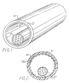
- Innerduct 10 formed in accordance with the present invention is illustrated.
- Innerduct 10 consists of outer tube 11 which is a polymer, typically polypropylene and preferably formed by an extrusion process.
- Outer tube 11 has liner 12 which is formed by the hot melt spray enhanced deposition of a low friction, lubricous material from a nozzle located downstream of the extrusion die as shown in Figure 4.
- the material to be deposited is polymeric, and may contain agents and fillers which contribute to the lowering of the frictional properties of the liner when subjected to pull-through of telecommunications cable 13.
- Suitable material for the inner liner are polymeric materials having a low coefficient of surface friction like polyethylene, polytetrafluoroethylene and polyvinylidene fluoride.
- Suitable friction-reducing fillers include graphite, silicone oils and polytetrafluoroethylene.
- the innerduct consists of a outer tube 21 which is a polymer formed by an extrusion process and has a textured liner 22 which is formed by the hot melt spray enhanced deposition of a low friction, lubricous polymeric material, which may contain agents and fillers which contribute to the lowering of the frictional properties of the liner when subjected to pull-through of telecommunications cable 13.
- Suitable material for the inner liner would be polyethylene, polytetrafluoroethylene and polyvinylidene fluoride. Where a polymeric material is used, it is not typically possible to create an atomized spray but a short-chained molecular spray is achievable at high temperatures.
- Figures 1 and 2 illustrate a innerduct whose cross section is circular
- the innerducts 10 and 20 may have any desired cross sectional shape such a square, rectangular, elliptical, triangular or other required shape for desired end use.
- the textured liner 22 may be formed with undulations having inward protecting ribs whose cross sections which may take on any shape including, but not limited to, square, rectangular, circular and polygonal shapes.
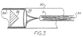
- FIG. 3 a schematic illustrating a preferred embodiment of a process of forming the extruded innerduct with the hot melt spray enhanced deposition of a liner is shown.
- An innerduct or conduit 30, at or near its extrusion temperature has contained therein preferably before extrusion, an orificed tube or nozzle 31 containing fluidized material.
- Melted or otherwise liquified polymeric material 34 at high temperature in is forced through the orifices of nozzle 31 which dispenses the polymeric material 34 in a radially symmetric pattern 35 by a pump, such as a piston pump (not shown).
- Preferable pressures at or above 1500 psi are used to "atomize" the liner material to provide the spray coating.
- the spray is generally as large as molecular fragmented polymer chains.
- the polymeric material 34 is deposited on the interior of innerduct 30 owing to the elevated temperature of the innerduct 30 as well as the material 34.
- a heated plug 38 acts to further fuse the polymeric material, causing it to form a film 39.
- the heated plug 38 may optionally have a countered edge which is in contact with the polymeric film 39, thereby contouring it with a desired texture.
- the liner material with or without fillers is deposed on the inner surface of the innerduct in form of a plurality of ultrathin strips which are continuous or discontinuous.
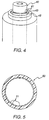
- One preferred method of depositing the coating is the use of a nozzle 40, Figure 4, which includes a plurality of nozzle openings 41.
- Nozzle 40 is located downstream of the extrusion die at a distance close enough to take advantage of the temperature of the extruded conduit.
- the openings 41 are preferably sized larger than those used in a liquified melt spray so that a more viscous liner material can be used.
- Nozzle 40 is positioned within an extrusion tube 45 such that an extruded innerduct passes between nozzle 40 and tube 45 through annular opening 44.
- nozzle 40 is positioned sufficiently close to the extrusion mandrel so that the temperature of the extruded innerduct has not cooled sufficiently.
- the temperature of the liner material is just below the extrusion temperature of the innerduct.
- a pressure of from 1000 to 1500 psi has been found suitable for deposit spraying a plurality of ribbon-like lubricous coating strips 51 in innerduct 50 ( Figure 5).
- strips 51 are discontinuous to minimize the amount of material needed, but is sufficient to facilitate and support the fiber optics or telecommunication cable as it is pulled through.
Landscapes
- Engineering & Computer Science (AREA)
- General Engineering & Computer Science (AREA)
- Mechanical Engineering (AREA)
- Life Sciences & Earth Sciences (AREA)
- Wood Science & Technology (AREA)
- Extrusion Moulding Of Plastics Or The Like (AREA)
- Lining Or Joining Of Plastics Or The Like (AREA)
- Adhesives Or Adhesive Processes (AREA)
- Braking Arrangements (AREA)
Abstract
Description
Claims (10)
- A method of cladding the inner surface of an innerduct or conduit (10, 20, 30, 50), said method comprising the steps of:a. fluidizing a polymeric material (34) to be deposited on said inner surface;b. heating the conduit (10, 20, 30, 50) to a temperature less than the melting point of said polymeric material (34) and conduit (10, 20, 30, 50);c. depositing the fluidized material (34) through a nozzle (31, 40) on the inner surface of said innerduct or conduit (10, 20, 30, 50) to provide a coating thereover.
- The method of claim 1, wherein said polymeric material (34) is deposited by spraying.
- The method of claim 1 or 2, wherein said polymeric material (34) is deposited in a plurality of ribbon-like strips (51).
- The method of claim 3, wherein said strips (51) are juxtapositioned next to each other along the inner surface of said conduit or innerduct (10, 20, 30, 50).
- The method according to anyone of claims 1 to 4, wherein said innerduct or conduit (10, 20, 30, 50) is a thermoplastic polymer formed by extrusion.
- The method according to anyone of claims 1 to 5, wherein the polymeric material (34) consists of a low friction polymer chosen from a group consisting of polyethylene, polytetrafluoroethylene, polyvinylidene fluoride, and mixtures of said polymers.
- The method according to anyone of claims 1 to 6, including the steps of mixing said polymers with materials chosen from a group consisting of graphite and silicone oils.
- The method according to anyone of claims 1 to 7, wherein the inner surface coating is imparted with textured surface by means of a heated plug (38) spaced apart from said nozzle (31, 40).
- The method according to anyone of claims 1 to 8, wherein the polymer is non-uniformly sprayed to a surface of said conduit (10, 20, 30, 50) to form a surface clad of non-uniform thickness.
- The method according to anyone of claims 1 to 9, wherein the polymer is filled with a powder chosen from a group consisting of graphite, talc and silica.
Applications Claiming Priority (5)
| Application Number | Priority Date | Filing Date | Title |
|---|---|---|---|
| US379880 | 1995-01-27 | ||
| US08/379,880 US5505992A (en) | 1995-01-27 | 1995-01-27 | Hot melt spray cladding of innerduct liner |
| US546018 | 1995-10-20 | ||
| US08/546,018 US5658613A (en) | 1995-01-27 | 1995-10-20 | Hot melt fluidized cladding of innerduct liner |
| PCT/US1996/001450 WO1996022873A1 (en) | 1995-01-27 | 1996-01-29 | Hot melt fluidized cladding of innerduct liner |
Publications (2)
| Publication Number | Publication Date |
|---|---|
| EP0805744A1 EP0805744A1 (en) | 1997-11-12 |
| EP0805744B1 true EP0805744B1 (en) | 2001-12-05 |
Family
ID=27008810
Family Applications (1)
| Application Number | Title | Priority Date | Filing Date |
|---|---|---|---|
| EP96905340A Expired - Lifetime EP0805744B1 (en) | 1995-01-27 | 1996-01-29 | Hot melt fluidized cladding of innerduct liner |
Country Status (7)
| Country | Link |
|---|---|
| US (2) | US5658613A (en) |
| EP (1) | EP0805744B1 (en) |
| AT (1) | ATE210013T1 (en) |
| DE (1) | DE69617640T2 (en) |
| ES (1) | ES2165975T3 (en) |
| PT (1) | PT805744E (en) |
| WO (1) | WO1996022873A1 (en) |
Families Citing this family (7)
| Publication number | Priority date | Publication date | Assignee | Title |
|---|---|---|---|---|
| FR2795879B1 (en) * | 1999-06-29 | 2001-10-12 | Usinage Tubes Pour Electr | ANNELE CONDUIT IN PRE-LUBRICATED SYNTHETIC MATERIAL, AND METHOD AND INSTALLATION FOR MAKING SAME |
| DE102006019562B4 (en) * | 2006-04-21 | 2014-07-31 | Masterflex Ag | Provided with reinforcing element hose line and method and apparatus for their preparation |
| US9004003B2 (en) * | 2009-06-25 | 2015-04-14 | Xerox Corporation | Apparatus for applying an acoustic dampening coating to the interior of a xerographic drum |
| AU2014200769B2 (en) * | 2010-02-26 | 2014-10-16 | Cadbury Uk Limited | Apparatus and method for manufacturing products |
| GB201003288D0 (en) * | 2010-02-26 | 2010-04-14 | Cadbury Uk Ltd | Apparatus and method for manufacturing products |
| DE202010017052U1 (en) * | 2010-12-24 | 2012-04-03 | Rehau Ag + Co. | Pipe or pipe fitting |
| US9709194B1 (en) * | 2014-04-24 | 2017-07-18 | Telebrands Corp. | Elongatable and retractable hose |
Family Cites Families (16)
| Publication number | Priority date | Publication date | Assignee | Title |
|---|---|---|---|---|
| NL6802285A (en) * | 1968-02-17 | 1969-08-19 | ||
| GB2123516B (en) * | 1982-04-30 | 1986-02-05 | Hakko Co | Lining old underground pipes |
| ATE55470T1 (en) * | 1982-05-14 | 1990-08-15 | Humes Ltd | PIPE LINING. |
| DE3326915A1 (en) * | 1983-07-26 | 1985-02-07 | Siemens AG, 1000 Berlin und 8000 München | Process and device for the interior coating of an elongated hollow element |
| DE3346028A1 (en) * | 1983-12-20 | 1985-06-20 | Siemens AG, 1000 Berlin und 8000 München | Process and device for producing a cross-linked shrink tube |
| US4791965A (en) * | 1987-02-13 | 1988-12-20 | James Hardie Irrigation, Inc. | Co-extruded tube |
| US4892442A (en) * | 1987-03-03 | 1990-01-09 | Dura-Line | Prelubricated innerduct |
| DE3802493C1 (en) * | 1988-01-28 | 1989-08-17 | Rehau Ag + Co, 8673 Rehau, De | |
| DE3910179C1 (en) * | 1989-03-29 | 1990-03-29 | J. Wagner Gmbh, 7990 Friedrichshafen, De | |
| US5087153A (en) * | 1989-08-23 | 1992-02-11 | Arnco Corporation | Internally spiraled duct and method of installation |
| US4996940A (en) * | 1989-11-17 | 1991-03-05 | Cleary John J | Method and apparatus for internally coating and strengthening conduit |
| US5271974A (en) * | 1990-04-30 | 1993-12-21 | Amsted Industries Incorporated | Improved cement and polyolefin lined product |
| JPH0731957B2 (en) * | 1990-11-30 | 1995-04-10 | 日本碍子株式会社 | Resin lining method for the inner surface of insulator |
| JPH0699136A (en) * | 1991-03-08 | 1994-04-12 | Suzuki Motor Corp | Coating of inner surface of pipe |
| AU3476693A (en) * | 1992-01-17 | 1993-08-03 | Arnco Corporation | Prelubricated duct |
| ATE174718T1 (en) * | 1994-03-15 | 1999-01-15 | Jansen Ag | CABLE PROTECTION TUBE |
-
1995
- 1995-10-20 US US08/546,018 patent/US5658613A/en not_active Expired - Fee Related
-
1996
- 1996-01-29 DE DE69617640T patent/DE69617640T2/en not_active Expired - Fee Related
- 1996-01-29 PT PT96905340T patent/PT805744E/en unknown
- 1996-01-29 ES ES96905340T patent/ES2165975T3/en not_active Expired - Lifetime
- 1996-01-29 WO PCT/US1996/001450 patent/WO1996022873A1/en not_active Ceased
- 1996-01-29 EP EP96905340A patent/EP0805744B1/en not_active Expired - Lifetime
- 1996-01-29 AT AT96905340T patent/ATE210013T1/en not_active IP Right Cessation
- 1996-04-25 US US08/638,014 patent/US5814371A/en not_active Expired - Fee Related
Also Published As
| Publication number | Publication date |
|---|---|
| ES2165975T3 (en) | 2002-04-01 |
| US5658613A (en) | 1997-08-19 |
| ATE210013T1 (en) | 2001-12-15 |
| EP0805744A1 (en) | 1997-11-12 |
| DE69617640D1 (en) | 2002-01-17 |
| WO1996022873A1 (en) | 1996-08-01 |
| PT805744E (en) | 2002-03-28 |
| DE69617640T2 (en) | 2002-08-08 |
| US5814371A (en) | 1998-09-29 |
Similar Documents
| Publication | Publication Date | Title |
|---|---|---|
| US5894042A (en) | Bacteriostatic coating of polymeric conduit | |
| EP0805744B1 (en) | Hot melt fluidized cladding of innerduct liner | |
| AU678448B2 (en) | Extrusion of thermally cross-linkable materials | |
| US5681623A (en) | Process for producing electrostatic clad conduit innerduct liner | |
| US5505992A (en) | Hot melt spray cladding of innerduct liner | |
| US5307843A (en) | Extrusion of tubes of fiber-reinforced thermoplastics | |
| US5501873A (en) | Impact spray cladding of innerduct liner | |
| EP0009312B1 (en) | Method and apparatus for manufacturing magnet wire and a magnet wire made thereby | |
| US3388425A (en) | Apparatus for coating the interior surfaces of hollow shaped articles | |
| GB2099357A (en) | Extruding around a metal pipe, a sheathing incorporating identifying strips | |
| JP2000506955A (en) | Plastic tube with multiple lumens | |
| EP0252749B1 (en) | Apparatus for continuously producing heat-shrinkable crosslinked resin tube | |
| CN1030544A (en) | Be used for producing continuously the device of heat-shrinkable cress linked resin tub | |
| US8316893B2 (en) | Fastening of pipes | |
| US5648102A (en) | Vacuum calibrator tool | |
| US20080128041A1 (en) | Duct having silicone inner striping and composition for lubricious stripe coating | |
| US4840552A (en) | Apparatus for continuously producing heat-shrinkable crosslinked resin tube | |
| IL45011A (en) | Fusible inserts | |
| RU2094228C1 (en) | Method of manufacturing inner surfaces of metallic pipes lined with polymeric material | |
| RU2176596C1 (en) | Method for making plastic tubes with colored stripes and apparatus for performing the same | |
| CA1167225A (en) | Making shrink-fit hoses | |
| JPH05200829A (en) | Sponge tube manufacturing method | |
| JPS602974B2 (en) | Rubber/plastic material extrusion coating machine | |
| JPS61185428A (en) | Solidification extrusion molding method of polymeric material and its mold equipment | |
| JPH0132054B2 (en) |
Legal Events
| Date | Code | Title | Description |
|---|---|---|---|
| PUAI | Public reference made under article 153(3) epc to a published international application that has entered the european phase |
Free format text: ORIGINAL CODE: 0009012 |
|
| 17P | Request for examination filed |
Effective date: 19970826 |
|
| AK | Designated contracting states |
Kind code of ref document: A1 Designated state(s): AT BE CH DE DK ES FR GB GR IE IT LI LU MC NL PT SE |
|
| 17Q | First examination report despatched |
Effective date: 19981102 |
|
| GRAG | Despatch of communication of intention to grant |
Free format text: ORIGINAL CODE: EPIDOS AGRA |
|
| GRAG | Despatch of communication of intention to grant |
Free format text: ORIGINAL CODE: EPIDOS AGRA |
|
| GRAH | Despatch of communication of intention to grant a patent |
Free format text: ORIGINAL CODE: EPIDOS IGRA |
|
| GRAH | Despatch of communication of intention to grant a patent |
Free format text: ORIGINAL CODE: EPIDOS IGRA |
|
| GRAA | (expected) grant |
Free format text: ORIGINAL CODE: 0009210 |
|
| AK | Designated contracting states |
Kind code of ref document: B1 Designated state(s): AT BE CH DE DK ES FR GB GR IE IT LI LU MC NL PT SE |
|
| PG25 | Lapsed in a contracting state [announced via postgrant information from national office to epo] |
Ref country code: NL Free format text: LAPSE BECAUSE OF FAILURE TO SUBMIT A TRANSLATION OF THE DESCRIPTION OR TO PAY THE FEE WITHIN THE PRESCRIBED TIME-LIMIT Effective date: 20011205 Ref country code: GR Free format text: LAPSE BECAUSE OF FAILURE TO SUBMIT A TRANSLATION OF THE DESCRIPTION OR TO PAY THE FEE WITHIN THE PRESCRIBED TIME-LIMIT Effective date: 20011205 |
|
| REF | Corresponds to: |
Ref document number: 210013 Country of ref document: AT Date of ref document: 20011215 Kind code of ref document: T |
|
| REG | Reference to a national code |
Ref country code: CH Ref legal event code: EP |
|
| REG | Reference to a national code |
Ref country code: GB Ref legal event code: IF02 |
|
| REG | Reference to a national code |
Ref country code: IE Ref legal event code: FG4D |
|
| REG | Reference to a national code |
Ref country code: CH Ref legal event code: NV Representative=s name: PATENTANWAELTE SCHAAD, BALASS, MENZL & PARTNER AG |
|
| REF | Corresponds to: |
Ref document number: 69617640 Country of ref document: DE Date of ref document: 20020117 |
|
| PG25 | Lapsed in a contracting state [announced via postgrant information from national office to epo] |
Ref country code: LU Free format text: LAPSE BECAUSE OF NON-PAYMENT OF DUE FEES Effective date: 20020129 Ref country code: IE Free format text: LAPSE BECAUSE OF NON-PAYMENT OF DUE FEES Effective date: 20020129 Ref country code: AT Free format text: LAPSE BECAUSE OF NON-PAYMENT OF DUE FEES Effective date: 20020129 |
|
| PG25 | Lapsed in a contracting state [announced via postgrant information from national office to epo] |
Ref country code: LI Free format text: LAPSE BECAUSE OF NON-PAYMENT OF DUE FEES Effective date: 20020131 Ref country code: CH Free format text: LAPSE BECAUSE OF NON-PAYMENT OF DUE FEES Effective date: 20020131 Ref country code: BE Free format text: LAPSE BECAUSE OF NON-PAYMENT OF DUE FEES Effective date: 20020131 |
|
| ET | Fr: translation filed | ||
| PG25 | Lapsed in a contracting state [announced via postgrant information from national office to epo] |
Ref country code: SE Free format text: LAPSE BECAUSE OF FAILURE TO SUBMIT A TRANSLATION OF THE DESCRIPTION OR TO PAY THE FEE WITHIN THE PRESCRIBED TIME-LIMIT Effective date: 20020305 Ref country code: GB Free format text: LAPSE BECAUSE OF NON-PAYMENT OF DUE FEES Effective date: 20020305 Ref country code: DK Free format text: LAPSE BECAUSE OF FAILURE TO SUBMIT A TRANSLATION OF THE DESCRIPTION OR TO PAY THE FEE WITHIN THE PRESCRIBED TIME-LIMIT Effective date: 20020305 |
|
| REG | Reference to a national code |
Ref country code: PT Ref legal event code: SC4A Free format text: AVAILABILITY OF NATIONAL TRANSLATION Effective date: 20011213 |
|
| REG | Reference to a national code |
Ref country code: ES Ref legal event code: FG2A Ref document number: 2165975 Country of ref document: ES Kind code of ref document: T3 |
|
| NLV1 | Nl: lapsed or annulled due to failure to fulfill the requirements of art. 29p and 29m of the patents act | ||
| BERE | Be: lapsed |
Owner name: TECHNOLOGY LICENSING CY Effective date: 20020131 |
|
| PG25 | Lapsed in a contracting state [announced via postgrant information from national office to epo] |
Ref country code: MC Free format text: LAPSE BECAUSE OF NON-PAYMENT OF DUE FEES Effective date: 20020801 Ref country code: DE Free format text: LAPSE BECAUSE OF NON-PAYMENT OF DUE FEES Effective date: 20020801 |
|
| REG | Reference to a national code |
Ref country code: CH Ref legal event code: PL |
|
| PLBE | No opposition filed within time limit |
Free format text: ORIGINAL CODE: 0009261 |
|
| STAA | Information on the status of an ep patent application or granted ep patent |
Free format text: STATUS: NO OPPOSITION FILED WITHIN TIME LIMIT |
|
| GBPC | Gb: european patent ceased through non-payment of renewal fee |
Effective date: 20020305 |
|
| REG | Reference to a national code |
Ref country code: IE Ref legal event code: MM4A |
|
| 26N | No opposition filed | ||
| PG25 | Lapsed in a contracting state [announced via postgrant information from national office to epo] |
Ref country code: FR Free format text: LAPSE BECAUSE OF NON-PAYMENT OF DUE FEES Effective date: 20021129 |
|
| REG | Reference to a national code |
Ref country code: FR Ref legal event code: ST |
|
| PG25 | Lapsed in a contracting state [announced via postgrant information from national office to epo] |
Ref country code: PT Free format text: LAPSE BECAUSE OF NON-PAYMENT OF DUE FEES Effective date: 20030731 |
|
| PG25 | Lapsed in a contracting state [announced via postgrant information from national office to epo] |
Ref country code: ES Free format text: LAPSE BECAUSE OF NON-PAYMENT OF DUE FEES Effective date: 20031122 |
|
| REG | Reference to a national code |
Ref country code: ES Ref legal event code: FD2A Effective date: 20031122 |
|
| PG25 | Lapsed in a contracting state [announced via postgrant information from national office to epo] |
Ref country code: IT Free format text: LAPSE BECAUSE OF NON-PAYMENT OF DUE FEES Effective date: 20050129 |
|
| PG25 | Lapsed in a contracting state [announced via postgrant information from national office to epo] |
Ref country code: PT Free format text: LAPSE BECAUSE OF NON-PAYMENT OF DUE FEES Effective date: 20020129 |
|
| PG25 | Lapsed in a contracting state [announced via postgrant information from national office to epo] |
Ref country code: FR Free format text: LAPSE BECAUSE OF NON-PAYMENT OF DUE FEES Effective date: 20020131 |
|
| PG25 | Lapsed in a contracting state [announced via postgrant information from national office to epo] |
Ref country code: ES Free format text: LAPSE BECAUSE OF NON-PAYMENT OF DUE FEES Effective date: 20020131 |