EP0805331A2 - Multi-tube heat exchanger - Google Patents
Multi-tube heat exchanger Download PDFInfo
- Publication number
- EP0805331A2 EP0805331A2 EP97302896A EP97302896A EP0805331A2 EP 0805331 A2 EP0805331 A2 EP 0805331A2 EP 97302896 A EP97302896 A EP 97302896A EP 97302896 A EP97302896 A EP 97302896A EP 0805331 A2 EP0805331 A2 EP 0805331A2
- Authority
- EP
- European Patent Office
- Prior art keywords
- heat exchanger
- tube
- heat transfer
- tank
- end portion
- Prior art date
- Legal status (The legal status is an assumption and is not a legal conclusion. Google has not performed a legal analysis and makes no representation as to the accuracy of the status listed.)
- Withdrawn
Links
- 229910000838 Al alloy Inorganic materials 0.000 claims description 3
- 238000003780 insertion Methods 0.000 description 11
- 230000037431 insertion Effects 0.000 description 11
- 239000003507 refrigerant Substances 0.000 description 10
- 230000007423 decrease Effects 0.000 description 3
- 238000005219 brazing Methods 0.000 description 2
- 230000001133 acceleration Effects 0.000 description 1
- 238000013459 approach Methods 0.000 description 1
- 238000005260 corrosion Methods 0.000 description 1
- 230000007797 corrosion Effects 0.000 description 1
- 230000003247 decreasing effect Effects 0.000 description 1
- 230000005484 gravity Effects 0.000 description 1
- 238000000034 method Methods 0.000 description 1
- 230000001105 regulatory effect Effects 0.000 description 1
Images


Classifications
-
- F—MECHANICAL ENGINEERING; LIGHTING; HEATING; WEAPONS; BLASTING
- F28—HEAT EXCHANGE IN GENERAL
- F28F—DETAILS OF HEAT-EXCHANGE AND HEAT-TRANSFER APPARATUS, OF GENERAL APPLICATION
- F28F9/00—Casings; Header boxes; Auxiliary supports for elements; Auxiliary members within casings
- F28F9/02—Header boxes; End plates
- F28F9/04—Arrangements for sealing elements into header boxes or end plates
- F28F9/16—Arrangements for sealing elements into header boxes or end plates by permanent joints, e.g. by rolling
- F28F9/18—Arrangements for sealing elements into header boxes or end plates by permanent joints, e.g. by rolling by welding
- F28F9/182—Arrangements for sealing elements into header boxes or end plates by permanent joints, e.g. by rolling by welding the heat-exchange conduits having ends with a particular shape, e.g. deformed; the heat-exchange conduits or end plates having supplementary joining means, e.g. abutments
-
- F—MECHANICAL ENGINEERING; LIGHTING; HEATING; WEAPONS; BLASTING
- F28—HEAT EXCHANGE IN GENERAL
- F28D—HEAT-EXCHANGE APPARATUS, NOT PROVIDED FOR IN ANOTHER SUBCLASS, IN WHICH THE HEAT-EXCHANGE MEDIA DO NOT COME INTO DIRECT CONTACT
- F28D1/00—Heat-exchange apparatus having stationary conduit assemblies for one heat-exchange medium only, the media being in contact with different sides of the conduit wall, in which the other heat-exchange medium is a large body of fluid, e.g. domestic or motor car radiators
- F28D1/02—Heat-exchange apparatus having stationary conduit assemblies for one heat-exchange medium only, the media being in contact with different sides of the conduit wall, in which the other heat-exchange medium is a large body of fluid, e.g. domestic or motor car radiators with heat-exchange conduits immersed in the body of fluid
- F28D1/04—Heat-exchange apparatus having stationary conduit assemblies for one heat-exchange medium only, the media being in contact with different sides of the conduit wall, in which the other heat-exchange medium is a large body of fluid, e.g. domestic or motor car radiators with heat-exchange conduits immersed in the body of fluid with tubular conduits
- F28D1/053—Heat-exchange apparatus having stationary conduit assemblies for one heat-exchange medium only, the media being in contact with different sides of the conduit wall, in which the other heat-exchange medium is a large body of fluid, e.g. domestic or motor car radiators with heat-exchange conduits immersed in the body of fluid with tubular conduits the conduits being straight
- F28D1/05316—Assemblies of conduits connected to common headers, e.g. core type radiators
- F28D1/05341—Assemblies of conduits connected to common headers, e.g. core type radiators with multiple rows of conduits or with multi-channel conduits combined with a particular flow pattern, e.g. multi-row multi-stage radiators
Definitions
- the present invention relates to a multi-tube heat exchanger used to, for example, an air conditioner for vehicles, and more particularly to an improved connection structure between tubes and a pair of tanks in the heat exchanger.
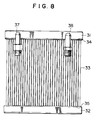
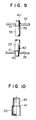
- a conventional multi-tube heat exchanger is constructed, for example, as shown in Figs. 8-10.
- a plurality of heat transfer tubes 33 each having a circular cross section are fluidly interconnected between an upper tank 31 and a lower tank 32. Connecting portions between tubes 33 and tanks 31 and 32 are structured, for example, as shown in Figs. 9 and 10. Each end portion of each heat transfer tube 33 is drawn, and a taper portion 41 and a contracted diameter portion 42 are formed.
- the respective contracted diameter portions 42 are inserted into holes 39 and 40 defined on walls 34 and 35 of upper and lower tanks 31 and 32, and the tanks 31 and 32 are communicated to each other via heat transfer tubes 33 by brazing the inner peripheries of the holes 39 and 40 and the outer surfaces of the contracted diameter portions 42 of the tubes 33.
- heat medium for example, refrigerant
- inlet pipe 37 heat medium introduced through an inlet pipe 37
- outlet pipe 38 heat medium introduced through an outlet pipe 38.
- Heat exchange is performed between the refrigerant flowing in heat transfer tubes 33 and air passing through gaps between the tubes 33.
- each taper portion 41 decreases as it approaches a corresponding contracted diameter portion 42, because the greatest diameter of the taper portion 41 is formed larger than the inner diameter of hole 39 or 40, the length of insertion of each heat transfer tube 33 into upper or lower tank 31 or 32 through hole 39 or 40 is maintained at a predetermined constant length.
- taper portion 41 and contracted diameter portion 42 are formed on an end portion of each heat transfer tube 33, and the inner diameter of this portion becomes small as compared with that of other portions of the tube 33, as shown in Fig. 10. Therefore, the pressure loss of heat medium (for example, refrigerant) flowing in each heat transfer tube 33 increases at this portion.
- heat medium for example, refrigerant
- the resistance P of a path having a path length"l" and an equivalent diameter (an inner diameter) "d” is represented by the following equation.
- P ⁇ (1/d) ⁇ (u 2 /2g)
- u is a flow rate
- g is an acceleration of gravity
- ⁇ is a coefficient.
- G 3600 ⁇ A ⁇ u
- A is a cross-sectional area of a path.
- the path length "l" is defined as an insertion length into a tank and the insertion length is the same for every tube having an arbitrary inner diameter (an inner di thoughr: d n ), from the above-described equations (1) and (2), the resistance P n of a path defined by a tube diameter d n and a cross-sectional area A n of the path is represented by the following equation.
- P n ⁇ (1/d n ) ⁇ (1/2g) ⁇ (G/3600A n ) 2
- a n will be explained.
- arrangement of tubes of a heat exchanger will be explained in reference to Fig. 12.
- the outer diameter of a tube is indicated by D
- an arrangement pitch of tubes in an air-flow direction is indicated by X
- an arrangement pitch of tubes in a direction perpendicular to the air-flow direction is indicated by Y.
- a number of tubes capable of being arranged in a unit area of a tank wall is considered at a condition where X/D and Y/D are constant, respectively, even in a case where the outer diameter of a tube varies. In this case, if the outer diameter of a tube becomes small, the number of tubes N n capable of being arranged in a unit area increases.
- This "d n " is determined at a condition where the thickness of a tube is constant even if the outer diameter of the tube varies.
- the thickness of a tube can be selected as a constant value in order to obtain a desired corrosion resistance even if the outer diameter of the tube varies.
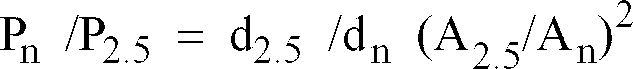
- the ratio of the path resistances is represented by the following equation.
- P n /P 2.5 d 2.5 /d n (A 2.5 /A n ) 2
- a multi-tube heat exchanger includes a pair of tanks spaced from each other and a plurality of heat transfer tubes each having a circular cross section and fluidly interconnected between the pair of tanks.
- Each of the plurality of heat transfer tubes has a first radially expanded portion at a first end portion engaging an outer surface of a wall of a first tank of the pair of tanks.
- Each heat transfer tube may have a second radially expanded portion at a second end portion engaging an outer surface of a wall of a second tank of the pair of tanks in addition to the first radially expanded portion.
- the first or the second radially expanded portion may be formed as an annular protruded portion formed on an outer surface of the first or the second end portion.
- the first or the second radially expanded portion may be formed as a radially expanded taper portion formed on a tip portion of the first or the second end portion.
- the wall of the first or the second tank may be formed as a burr at a position connected with the first or the second end portion, and the radially expanded taper portion may be fitted onto an outer surface of the burr.
- the present invention can be appropriately applied to a heat exchanger having heat transfer tubes with an inner diameter of not more than 2 mm.
- a diameter contracted portion such as one in a conventional heat exchanger is not formed at an end portion of a heat transfer tube even if a radially expanded portion is formed, increase of pressure loss of a flowing heat medium in the tube can be prevented, particularly, effectively in a small-diameter tube such as one having a diameter of not more than 2 mm.
- the radially expanded portion engages an outer surface of a wall of a tank, the insertion length of the tube end portion into the tank can be precisely regulated, or a structure where the tube end portion is not inserted into the tank can be employed.
- a heat exchanger having a desired dimension can be obtained, and the pressure loss in the circuit of the heat exchanger can be further decreased, thereby achieving a high heat exchange performance.
- the radially expanded portion is formed as an annular protruded portion formed on an outer surface of the tube end portion, a diameter contracted portion is not formed at all, increase of pressure loss can be effectively prevented. Because the annular protruded portion is engaged to the outer surface of the tank, the insertion length of the tube end portion into the tank is easily and precisely set at a predetermined length.
- the tube end portion When the radially expanded portion is formed as a radially expanded taper portion formed on a tip portion of the tube end portion and the radially expanded taper portion is fitted onto an outer surface of a burr formed on a tank wall at a position connected with the tube end portion, the tube end portion can be connected to the burr on the tank wall without being projected into the tank and without forming a diameter contracted portion.
- the flow in the tank can be smoothened as well as the pressure loss in the tank can be suppressed small, and therefore, increase of pressure loss as the whole of the heat exchanger can be prevented more effectively.
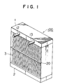
- Fig. 1 is a perspective view of a multi-tube heat exchanger according to a first embodiment of the present invention.
- Fig. 2 is an enlarged, partial, vertical sectional view of the heat exchanger depicted in Fig. 1, showing connecting portions of a heat transfer tube and tank walls.
- Fig. 3 is an enlarged, partial, vertical sectional view of a connecting portion of an end portion of a heat transfer tube and a tank wall depicted in Fig. 2.
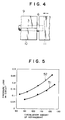
- Fig. 4 is a side view of upper and lower dies and a jig for forming an radially expanded portion on a tube end portion of a tube depicted in Fig. 2.
- Fig. 5 is a graph showing relationships between a pressure loss in a circuit and a circulation amount of refrigerant in the heat exchangers depicted in Figs. 1 and 8.
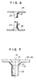
- Fig. 6 is a partial, vertical sectional view of connecting portions of a heat transfer tube and tank walls in a heat exchanger according to a second embodiment of the present invention.
- Fig. 7 is an enlarged, partial, vertical sectional view of a connecting portion of an end portion of a heat transfer tube and a tank wall depicted in Fig. 6.
- Fig. 8 is an elevational view of a conventional heat exchanger.
- Fig. 9 is an enlarged, partial, vertical sectional view of the heat exchanger depicted in Fig. 8, showing connecting portions of a heat transfer tube and tank walls.
- Fig. 10 is an enlarged, partial, vertical sectional view of a connecting portion of an end portion of a heat transfer tube and a tank wall depicted in Fig. 9.
- Fig. 11 is a graph showing a relationship between an inner diameter of a heat transfer tube and a ratio of path resistances.
- Fig. 12 is a schematic plan view of arranged heat transfer tubes.
- Heat exchanger 100 includes a pair of tanks 1 and 2, for example, an upper tank 1 and a lower tank 2.
- a plurality of heat transfer tubes 3 each having a circular cross section and a small diameter (for example, refrigerant tubes) are fluidly interconnected between tanks 1 and 2.
- at least heat transfer tubes 3 are made from an aluminum alloy, and fixed to tanks 1 and 2 by brazing.
- Inlet pipe 12 and outlet pipe 13 are connected to tank 1.
- a supporting plate 20 is provided at a position corresponding to a middle portion of each heat transfer tube 3 in the axial direction in order to support the tubes 3, this supporting plate 20 may be omitted.
- Heat exchange medium for example, refrigerant
- tank 1 is introduced into tank 1 through inlet pipe 12, and after circulation through heat exchanger 100, the heat exchange medium flows out of tank 1 through outlet pipe 13. Heat exchange is performed between the refrigerant flowing in heat transfer tubes 3 and air passing through gaps between the tubes 3.
- annular protruded portion 6 provided as a radially expanded portion is formed at least on a first end portion 3a of heat transfer tube 3, in this embodiment, on each of first and second end portion 3a and 3b.
- the annular protruded portions 6 engage the outer surfaces of a tank wall 4 of tank 1 and a tank wall 5 of tank 2, respectively.
- These annular protruded portions 6 are formed on the outer surface of each heat transfer tube 3 at both end portions 3a and 3b.
- Tube insertion holes 7 and 8 are defined on tank walls 4 and 5, respectively. End portions 3a and 3b of each heat transfer tube 3 are inserted into tube insertion holes 7 and 8, respectively, and are projected into tanks 1 and 2 at predetermined insertion lengths, respectively.
- annular protruded portion 6 can be formed by holding a heat transfer tube 3 from both sides by an upper die 9 and a lower die 10 and pressing the tube end portion by a jig 11 in a direction shown by an arrow.
- Fig. 5 shows a relationship between a pressure loss in a circuit and a circulation amount of refrigerant for comparing the performance of the heat exchanger depicted in Figs. 1-3 with the performance of the conventional heat exchanger depicted in Figs. 8-10.
- each of heat transfer tubes 3 has an inner diameter of 2.4 mm at its tube end portion
- each of heat transfer tubes 33 has an inner diameter of 1.8 mm at its diameter contracted tube end portion.
- the inner diameter of a tube portion except tube end portions is the same in both of the heat exchanger 100 of this embodiment and the conventional heat exchanger.
- the heat exchanger 100 of this embodiment indicates a pressure-loss property 51
- the conventional heat exchanger indicates a pressure-loss property 52.
- Figs. 6 and 7 show a structure of a connecting portion of tube end portions and tank walls in a multi-tube heat exchanger according to a second embodiment of the present invention.
- a radially expanded taper portion 12 is formed as a radially expanded portion on each of tip portions of the tube end portions of each heat transfer tube 23.
- Each heat transfer tubes 23 has an inner diameter of not more than 2 mm and is made from an aluminum alloy.
- a burr 14 is formed at a position connected with each corresponding tube end portion. Burr 14 is formed as a shape along the shape of radially expanded taper portion 12.
- Radially expanded taper portion 12 is fitted onto an outer surface 15 of burr 14, and an inner surface 13 of the radially expanded taper portion 12 and the outer surface 15 of burr 14 are brazed to each other.
- a diameter contracted portion is not formed on a tube end portion of heat transfer tube 23 as in a conventional heat exchanger, increase of pressure loss at a connecting portion of the tube end portion and a tank wall can be effectively prevented. Further, in this embodiment, because the tube end portion is not inserted into the interior of a tank, the flow in the tank can be smoothened as well as the pressure loss in the tank can be suppressed small, the pressure loss in the whole circuit of the heat exchanger can be suppressed smaller.
- multi-tube heat exchangers arranged with tanks 1 and 2 in a vertical direction have been explained in the above-described embodiments, the arrangement direction of tanks may be in a horizontal or other directions.
Landscapes
- Engineering & Computer Science (AREA)
- Physics & Mathematics (AREA)
- Thermal Sciences (AREA)
- Mechanical Engineering (AREA)
- General Engineering & Computer Science (AREA)
- Heat-Exchange Devices With Radiators And Conduit Assemblies (AREA)
- Details Of Heat-Exchange And Heat-Transfer (AREA)
Abstract
Description
- The present invention relates to a multi-tube heat exchanger used to, for example, an air conditioner for vehicles, and more particularly to an improved connection structure between tubes and a pair of tanks in the heat exchanger.
- A conventional multi-tube heat exchanger is constructed, for example, as shown in Figs. 8-10. In Fig. 8, a plurality of
heat transfer tubes 33 each having a circular cross section are fluidly interconnected between anupper tank 31 and alower tank 32. Connecting portions betweentubes 33 andtanks heat transfer tube 33 is drawn, and ataper portion 41 and a contracteddiameter portion 42 are formed. The respective contracteddiameter portions 42 are inserted intoholes walls lower tanks tanks heat transfer tubes 33 by brazing the inner peripheries of theholes diameter portions 42 of thetubes 33. - In such a heat exchanger, heat medium (for example, refrigerant) introduced through an
inlet pipe 37 is circulated in the heat exchanger and thereafter discharged through anoutlet pipe 38. Heat exchange is performed between the refrigerant flowing inheat transfer tubes 33 and air passing through gaps between thetubes 33. - In the above-described heat exchanger, insertion of
heat transfer tubes 33 intoholes walls lower tanks diameter portions 42 on the end portions of eachheat transfer tubes 33. Further, although the diameter of eachtaper portion 41 decreases as it approaches a corresponding contracteddiameter portion 42, because the greatest diameter of thetaper portion 41 is formed larger than the inner diameter ofhole heat transfer tube 33 into upper orlower tank hole - In such a heat exchanger, however,
taper portion 41 and contracteddiameter portion 42 are formed on an end portion of eachheat transfer tube 33, and the inner diameter of this portion becomes small as compared with that of other portions of thetube 33, as shown in Fig. 10. Therefore, the pressure loss of heat medium (for example, refrigerant) flowing in eachheat transfer tube 33 increases at this portion. - Generally, the resistance P of a path having a path length"l" and an equivalent diameter (an inner diameter) "d" is represented by the following equation.

- Further, the relationship between a circulation amount of refrigerant G and a flow rate "u" is represented by the following equation.

- When the circulation amount of refrigerant G is constant, the path length "l" is defined as an insertion length into a tank and the insertion length is the same for every tube having an arbitrary inner diameter (an inner diamenter: dn ), from the above-described equations (1) and (2), the resistance P n of a path defined by a tube diameter dn and a cross-sectional area A n of the path is represented by the following equation.

- Next, An will be explained. First, arrangement of tubes of a heat exchanger will be explained in reference to Fig. 12. The outer diameter of a tube is indicated by D, an arrangement pitch of tubes in an air-flow direction is indicated by X and an arrangement pitch of tubes in a direction perpendicular to the air-flow direction is indicated by Y. Where, a number of tubes capable of being arranged in a unit area of a tank wall is considered at a condition where X/D and Y/D are constant, respectively, even in a case where the outer diameter of a tube varies. In this case, if the outer diameter of a tube becomes small, the number of tubes N n capable of being arranged in a unit area increases. Where, the cross-sectional area An of the path is calculated by A n = (1/4) · π · d n 2 × N n . This "dn " is determined at a condition where the thickness of a tube is constant even if the outer diameter of the tube varies. The thickness of a tube can be selected as a constant value in order to obtain a desired corrosion resistance even if the outer diameter of the tube varies. When the relationship between the diameter "dn " of a tube and the resistance "P n " of a path is determined as a ratio of the resistance to that at a condition of an inner diameter of 2.5 mm, the ratio of the path resistances is represented by the following equation.
- As shown in Fig. 11, as the inner diameter of
tube 33 decreases, the ratio of the path resistances at an insertion portion rapidly increases. Therefore, when the thickness of a tube is constant, if the outer diameter of the tube decreases, in a case where diameter contractedportions 42 are formed as described above, the pressure loss in the circuit of the heat exchanger may rapidly increase as well as the performance thereof may rapidly deteriorate. Particularly, this becomes remarkable in a range of an inner diameter of not more than 2 mm. - It would be desirable to provide a multi-tube heat exchanger having small-diameter heat transfer tubes which can prevent increase of pressure loss and indicate an excellent heat exchange ability.
- A multi-tube heat exchanger according to the present invention includes a pair of tanks spaced from each other and a plurality of heat transfer tubes each having a circular cross section and fluidly interconnected between the pair of tanks. Each of the plurality of heat transfer tubes has a first radially expanded portion at a first end portion engaging an outer surface of a wall of a first tank of the pair of tanks.
- Each heat transfer tube may have a second radially expanded portion at a second end portion engaging an outer surface of a wall of a second tank of the pair of tanks in addition to the first radially expanded portion.
- The first or the second radially expanded portion may be formed as an annular protruded portion formed on an outer surface of the first or the second end portion. Alternatively, the first or the second radially expanded portion may be formed as a radially expanded taper portion formed on a tip portion of the first or the second end portion. In the latter case, the wall of the first or the second tank may be formed as a burr at a position connected with the first or the second end portion, and the radially expanded taper portion may be fitted onto an outer surface of the burr.
- The present invention can be appropriately applied to a heat exchanger having heat transfer tubes with an inner diameter of not more than 2 mm.
- In such a multi-tube heat exchanger, since a diameter contracted portion such as one in a conventional heat exchanger is not formed at an end portion of a heat transfer tube even if a radially expanded portion is formed, increase of pressure loss of a flowing heat medium in the tube can be prevented, particularly, effectively in a small-diameter tube such as one having a diameter of not more than 2 mm. Because the radially expanded portion engages an outer surface of a wall of a tank, the insertion length of the tube end portion into the tank can be precisely regulated, or a structure where the tube end portion is not inserted into the tank can be employed. As a result, a heat exchanger having a desired dimension can be obtained, and the pressure loss in the circuit of the heat exchanger can be further decreased, thereby achieving a high heat exchange performance.
- When the radially expanded portion is formed as an annular protruded portion formed on an outer surface of the tube end portion, a diameter contracted portion is not formed at all, increase of pressure loss can be effectively prevented. Because the annular protruded portion is engaged to the outer surface of the tank, the insertion length of the tube end portion into the tank is easily and precisely set at a predetermined length.
- When the radially expanded portion is formed as a radially expanded taper portion formed on a tip portion of the tube end portion and the radially expanded taper portion is fitted onto an outer surface of a burr formed on a tank wall at a position connected with the tube end portion, the tube end portion can be connected to the burr on the tank wall without being projected into the tank and without forming a diameter contracted portion. As a result, the flow in the tank can be smoothened as well as the pressure loss in the tank can be suppressed small, and therefore, increase of pressure loss as the whole of the heat exchanger can be prevented more effectively.
- Further objects, features, and advantages of the present invention will be understood from the following detailed description of the embodiments of the present invention with reference to the appropriate figures.
- Some embodiments of the invention will now be described with reference to the appropriate figures, which are given by way of example only, and are not intended to limit the present invention.
- Fig. 1 is a perspective view of a multi-tube heat exchanger according to a first embodiment of the present invention.
- Fig. 2 is an enlarged, partial, vertical sectional view of the heat exchanger depicted in Fig. 1, showing connecting portions of a heat transfer tube and tank walls.
- Fig. 3 is an enlarged, partial, vertical sectional view of a connecting portion of an end portion of a heat transfer tube and a tank wall depicted in Fig. 2.
- Fig. 4 is a side view of upper and lower dies and a jig for forming an radially expanded portion on a tube end portion of a tube depicted in Fig. 2.
- Fig. 5 is a graph showing relationships between a pressure loss in a circuit and a circulation amount of refrigerant in the heat exchangers depicted in Figs. 1 and 8.
- Fig. 6 is a partial, vertical sectional view of connecting portions of a heat transfer tube and tank walls in a heat exchanger according to a second embodiment of the present invention.
- Fig. 7 is an enlarged, partial, vertical sectional view of a connecting portion of an end portion of a heat transfer tube and a tank wall depicted in Fig. 6.
- Fig. 8 is an elevational view of a conventional heat exchanger.
- Fig. 9 is an enlarged, partial, vertical sectional view of the heat exchanger depicted in Fig. 8, showing connecting portions of a heat transfer tube and tank walls.
- Fig. 10 is an enlarged, partial, vertical sectional view of a connecting portion of an end portion of a heat transfer tube and a tank wall depicted in Fig. 9.
- Fig. 11 is a graph showing a relationship between an inner diameter of a heat transfer tube and a ratio of path resistances.
- Fig. 12 is a schematic plan view of arranged heat transfer tubes.
- Referring to Figs. 1-3, a
multi-tube heat exchanger 100 is provided according to a first embodiment of the present invention.Heat exchanger 100 includes a pair oftanks 1 and 2, for example, an upper tank 1 and alower tank 2. A plurality ofheat transfer tubes 3 each having a circular cross section and a small diameter (for example, refrigerant tubes) are fluidly interconnected betweentanks 1 and 2. In this embodiment, at leastheat transfer tubes 3 are made from an aluminum alloy, and fixed totanks 1 and 2 by brazing.Inlet pipe 12 andoutlet pipe 13 are connected to tank 1. In this embodiment, although a supportingplate 20 is provided at a position corresponding to a middle portion of eachheat transfer tube 3 in the axial direction in order to support thetubes 3, this supportingplate 20 may be omitted. Heat exchange medium, for example, refrigerant, is introduced into tank 1 throughinlet pipe 12, and after circulation throughheat exchanger 100, the heat exchange medium flows out of tank 1 throughoutlet pipe 13. Heat exchange is performed between the refrigerant flowing inheat transfer tubes 3 and air passing through gaps between thetubes 3. - As depicted in Figs. 2 and 3, an annular protruded
portion 6 provided as a radially expanded portion is formed at least on a first end portion 3a ofheat transfer tube 3, in this embodiment, on each of first andsecond end portion 3a and 3b. The annular protrudedportions 6 engage the outer surfaces of atank wall 4 of tank 1 and atank wall 5 oftank 2, respectively. These annular protrudedportions 6 are formed on the outer surface of eachheat transfer tube 3 at bothend portions 3a and 3b. Tube insertion holes 7 and 8 are defined ontank walls End portions 3a and 3b of eachheat transfer tube 3 are inserted into tube insertion holes 7 and 8, respectively, and are projected intotanks 1 and 2 at predetermined insertion lengths, respectively. - Where, although a method for forming annular protruded
portion 6 is not particularly restricted, for example, as shown in Fig. 4, the annular protrudedportion 6 can be formed by holding aheat transfer tube 3 from both sides by anupper die 9 and alower die 10 and pressing the tube end portion by a jig 11 in a direction shown by an arrow. - In such a
multi-tube heat exchanger 100 thus constructed, since annular protrudedportion 6 provided as a radially expanded portion is formed on each tube end portion but a diameter contracted portion is not formed as in a conventional heat exchanger, increase of pressure loss at a connecting portion of a heat transfer tube and a tank wall can be prevented. Further, the insertion length of each oftube end portions 3a and 3b is set to a predetermined desired length easily and precisely by engagement of annular protrudedportion 6 to the outer surface of each oftank walls multi-tube heat exchanger 100 having a desired dimension and a high heat exchange performance can be realized. - Fig. 5 shows a relationship between a pressure loss in a circuit and a circulation amount of refrigerant for comparing the performance of the heat exchanger depicted in Figs. 1-3 with the performance of the conventional heat exchanger depicted in Figs. 8-10.
- In
heat exchanger 100 depicted in Figs. 1-3, each ofheat transfer tubes 3 has an inner diameter of 2.4 mm at its tube end portion, and in the heat exchanger depicted in Figs. 8-10, each ofheat transfer tubes 33 has an inner diameter of 1.8 mm at its diameter contracted tube end portion. The inner diameter of a tube portion except tube end portions is the same in both of theheat exchanger 100 of this embodiment and the conventional heat exchanger. Theheat exchanger 100 of this embodiment indicates a pressure-loss property 51, and the conventional heat exchanger indicates a pressure-loss property 52. Thus, in the present invention, increase of pressure loss can be effectively prevented. - Figs. 6 and 7 show a structure of a connecting portion of tube end portions and tank walls in a multi-tube heat exchanger according to a second embodiment of the present invention. In this embodiment, a radially expanded
taper portion 12 is formed as a radially expanded portion on each of tip portions of the tube end portions of eachheat transfer tube 23. Eachheat transfer tubes 23 has an inner diameter of not more than 2 mm and is made from an aluminum alloy. On each oftank walls burr 14 is formed at a position connected with each corresponding tube end portion.Burr 14 is formed as a shape along the shape of radially expandedtaper portion 12. Radially expandedtaper portion 12 is fitted onto anouter surface 15 ofburr 14, and aninner surface 13 of the radially expandedtaper portion 12 and theouter surface 15 ofburr 14 are brazed to each other. - In this embodiment, because a diameter contracted portion is not formed on a tube end portion of
heat transfer tube 23 as in a conventional heat exchanger, increase of pressure loss at a connecting portion of the tube end portion and a tank wall can be effectively prevented. Further, in this embodiment, because the tube end portion is not inserted into the interior of a tank, the flow in the tank can be smoothened as well as the pressure loss in the tank can be suppressed small, the pressure loss in the whole circuit of the heat exchanger can be suppressed smaller. - Although multi-tube heat exchangers arranged with
tanks 1 and 2 in a vertical direction have been explained in the above-described embodiments, the arrangement direction of tanks may be in a horizontal or other directions.
Claims (8)
Applications Claiming Priority (2)
| Application Number | Priority Date | Filing Date | Title |
|---|---|---|---|
| JP132600/96 | 1996-04-30 | ||
| JP13260096A JPH09296994A (en) | 1996-04-30 | 1996-04-30 | Heat exchanger |
Publications (2)
| Publication Number | Publication Date |
|---|---|
| EP0805331A2 true EP0805331A2 (en) | 1997-11-05 |
| EP0805331A3 EP0805331A3 (en) | 1998-07-08 |
Family
ID=15085133
Family Applications (1)
| Application Number | Title | Priority Date | Filing Date |
|---|---|---|---|
| EP97302896A Withdrawn EP0805331A3 (en) | 1996-04-30 | 1997-04-28 | Multi-tube heat exchanger |
Country Status (2)
| Country | Link |
|---|---|
| EP (1) | EP0805331A3 (en) |
| JP (1) | JPH09296994A (en) |
Cited By (8)
| Publication number | Priority date | Publication date | Assignee | Title |
|---|---|---|---|---|
| FR2799826A1 (en) * | 1999-09-28 | 2001-04-20 | Valeo Thermique Moteur Sa | Brazed aluminium heat exchanger, esp for motor vehicle, has finned tubes made with end collars for brazing round holes in manifold |
| EP1598626A1 (en) * | 2004-05-19 | 2005-11-23 | Outokumpu Oyj | High pressure, high temperature charge air cooler |
| WO2007082515A1 (en) * | 2006-01-23 | 2007-07-26 | Alstom Technology Ltd. | Tube bundle heat exchanger |
| US8177932B2 (en) | 2009-02-27 | 2012-05-15 | International Mezzo Technologies, Inc. | Method for manufacturing a micro tube heat exchanger |
| US10094626B2 (en) | 2015-10-07 | 2018-10-09 | Arvos Ljungstrom Llc | Alternating notch configuration for spacing heat transfer sheets |
| US10175006B2 (en) | 2013-11-25 | 2019-01-08 | Arvos Ljungstrom Llc | Heat transfer elements for a closed channel rotary regenerative air preheater |
| US10197337B2 (en) | 2009-05-08 | 2019-02-05 | Arvos Ljungstrom Llc | Heat transfer sheet for rotary regenerative heat exchanger |
| US10378829B2 (en) | 2012-08-23 | 2019-08-13 | Arvos Ljungstrom Llc | Heat transfer assembly for rotary regenerative preheater |
Families Citing this family (2)
| Publication number | Priority date | Publication date | Assignee | Title |
|---|---|---|---|---|
| CN105423777B (en) * | 2015-12-29 | 2018-02-13 | 山东利能换热器有限公司 | Header body package UNICOM directional bearing heat interchanger |
| CN105627627B (en) * | 2016-01-21 | 2017-10-31 | 徐明海 | Self-locking fixer and method between a kind of pile foundation buried tube heat exchanger PE pipes and reinforcing bar |
Family Cites Families (5)
| Publication number | Priority date | Publication date | Assignee | Title |
|---|---|---|---|---|
| FR2031668A5 (en) * | 1969-02-03 | 1970-11-20 | Chausson Usines Sa | |
| FR2690515A1 (en) * | 1992-04-24 | 1993-10-29 | Valeo Thermique Moteur Sa | Heat exchanger with oblong section tubes, in particular for motor vehicles. |
| DE4325427A1 (en) * | 1993-07-29 | 1995-02-02 | Behr Gmbh & Co | Heat exchanger, in particular a motor vehicle radiator |
| DE69517710T2 (en) * | 1994-07-22 | 2001-02-22 | Mitsubishi Denki K.K., Tokio/Tokyo | Heat exchanger |
| JPH09280781A (en) * | 1996-04-17 | 1997-10-31 | Sanden Corp | Multitubular heat exchanger |
-
1996
- 1996-04-30 JP JP13260096A patent/JPH09296994A/en active Pending
-
1997
- 1997-04-28 EP EP97302896A patent/EP0805331A3/en not_active Withdrawn
Cited By (13)
| Publication number | Priority date | Publication date | Assignee | Title |
|---|---|---|---|---|
| FR2799826A1 (en) * | 1999-09-28 | 2001-04-20 | Valeo Thermique Moteur Sa | Brazed aluminium heat exchanger, esp for motor vehicle, has finned tubes made with end collars for brazing round holes in manifold |
| EP1598626A1 (en) * | 2004-05-19 | 2005-11-23 | Outokumpu Oyj | High pressure, high temperature charge air cooler |
| US6997248B2 (en) | 2004-05-19 | 2006-02-14 | Outokumpu Oyj | High pressure high temperature charge air cooler |
| WO2007082515A1 (en) * | 2006-01-23 | 2007-07-26 | Alstom Technology Ltd. | Tube bundle heat exchanger |
| US9534850B2 (en) | 2006-01-23 | 2017-01-03 | Arvos Technology Limited | Tube bundle heat exchanger |
| US10914527B2 (en) | 2006-01-23 | 2021-02-09 | Arvos Gmbh | Tube bundle heat exchanger |
| US8177932B2 (en) | 2009-02-27 | 2012-05-15 | International Mezzo Technologies, Inc. | Method for manufacturing a micro tube heat exchanger |
| US10982908B2 (en) | 2009-05-08 | 2021-04-20 | Arvos Ljungstrom Llc | Heat transfer sheet for rotary regenerative heat exchanger |
| US10197337B2 (en) | 2009-05-08 | 2019-02-05 | Arvos Ljungstrom Llc | Heat transfer sheet for rotary regenerative heat exchanger |
| US10378829B2 (en) | 2012-08-23 | 2019-08-13 | Arvos Ljungstrom Llc | Heat transfer assembly for rotary regenerative preheater |
| US11092387B2 (en) | 2012-08-23 | 2021-08-17 | Arvos Ljungstrom Llc | Heat transfer assembly for rotary regenerative preheater |
| US10175006B2 (en) | 2013-11-25 | 2019-01-08 | Arvos Ljungstrom Llc | Heat transfer elements for a closed channel rotary regenerative air preheater |
| US10094626B2 (en) | 2015-10-07 | 2018-10-09 | Arvos Ljungstrom Llc | Alternating notch configuration for spacing heat transfer sheets |
Also Published As
| Publication number | Publication date |
|---|---|
| JPH09296994A (en) | 1997-11-18 |
| EP0805331A3 (en) | 1998-07-08 |
Similar Documents
| Publication | Publication Date | Title |
|---|---|---|
| EP0660063A2 (en) | Heat exchanger | |
| US5457885A (en) | Heat exchanger and method for producing the same | |
| US4971145A (en) | Heat exchanger header | |
| US5348081A (en) | High capacity automotive condenser | |
| USRE35655E (en) | Condenser for use in a car cooling system | |
| US5341870A (en) | Evaporator or evaporator/condenser | |
| US5918667A (en) | Heat exchanger | |
| US6904963B2 (en) | Heat exchanger | |
| EP1298401A2 (en) | Heat exchanger | |
| EP0881449A2 (en) | Refrigerant tubes for heat exchangers | |
| EP0237164A1 (en) | Method of making a heat exchanger | |
| US20020134537A1 (en) | Heat exchanger | |
| US5896923A (en) | Heat exchanger having downsized header tank | |
| EP0860676A2 (en) | Heat exchanger | |
| US6293011B1 (en) | Heat exchanger for vehicle air conditioner | |
| EP0805331A2 (en) | Multi-tube heat exchanger | |
| US20050061492A1 (en) | Heat exchanger and process for fabricating same | |
| US5246064A (en) | Condenser for use in a car cooling system | |
| JPH0684188U (en) | Heat exchanger | |
| US5190100A (en) | Condenser for use in a car cooling system | |
| US5494099A (en) | Heat exchanger | |
| US7174953B2 (en) | Stacking-type, multi-flow, heat exchanger | |
| EP0802386B1 (en) | Multi-tube heat exchanger | |
| EP0798530A1 (en) | Heat exchanger | |
| EP0633435A1 (en) | Condenser for air-conditioning systems, in particular for motor vehicles |
Legal Events
| Date | Code | Title | Description |
|---|---|---|---|
| PUAI | Public reference made under article 153(3) epc to a published international application that has entered the european phase |
Free format text: ORIGINAL CODE: 0009012 |
|
| AK | Designated contracting states |
Kind code of ref document: A2 Designated state(s): DE FR GB IT SE |
|
| PUAL | Search report despatched |
Free format text: ORIGINAL CODE: 0009013 |
|
| AK | Designated contracting states |
Kind code of ref document: A3 Designated state(s): DE FR GB IT SE |
|
| 17P | Request for examination filed |
Effective date: 19981130 |
|
| 17Q | First examination report despatched |
Effective date: 20000907 |
|
| STAA | Information on the status of an ep patent application or granted ep patent |
Free format text: STATUS: THE APPLICATION IS DEEMED TO BE WITHDRAWN |
|
| 18D | Application deemed to be withdrawn |
Effective date: 20010118 |