EP0805084B1 - Procedure for the controlled braking of a vehicle - Google Patents
Procedure for the controlled braking of a vehicle Download PDFInfo
- Publication number
- EP0805084B1 EP0805084B1 EP97106867A EP97106867A EP0805084B1 EP 0805084 B1 EP0805084 B1 EP 0805084B1 EP 97106867 A EP97106867 A EP 97106867A EP 97106867 A EP97106867 A EP 97106867A EP 0805084 B1 EP0805084 B1 EP 0805084B1
- Authority
- EP
- European Patent Office
- Prior art keywords
- braking
- brake
- distribution key
- force distribution
- brake actuator
- Prior art date
- Legal status (The legal status is an assumption and is not a legal conclusion. Google has not performed a legal analysis and makes no representation as to the accuracy of the status listed.)
- Expired - Lifetime
Links
- 238000000034 method Methods 0.000 title claims description 16
- 230000001133 acceleration Effects 0.000 description 2
- 230000001934 delay Effects 0.000 description 2
- 238000010586 diagram Methods 0.000 description 2
- 230000000977 initiatory effect Effects 0.000 description 2
- 230000005540 biological transmission Effects 0.000 description 1
- 230000006870 function Effects 0.000 description 1
- 230000005484 gravity Effects 0.000 description 1
- 230000002265 prevention Effects 0.000 description 1
- 230000001105 regulatory effect Effects 0.000 description 1
- 230000008054 signal transmission Effects 0.000 description 1
- 230000001960 triggered effect Effects 0.000 description 1
Images
Classifications
-
- B—PERFORMING OPERATIONS; TRANSPORTING
- B60—VEHICLES IN GENERAL
- B60T—VEHICLE BRAKE CONTROL SYSTEMS OR PARTS THEREOF; BRAKE CONTROL SYSTEMS OR PARTS THEREOF, IN GENERAL; ARRANGEMENT OF BRAKING ELEMENTS ON VEHICLES IN GENERAL; PORTABLE DEVICES FOR PREVENTING UNWANTED MOVEMENT OF VEHICLES; VEHICLE MODIFICATIONS TO FACILITATE COOLING OF BRAKES
- B60T8/00—Arrangements for adjusting wheel-braking force to meet varying vehicular or ground-surface conditions, e.g. limiting or varying distribution of braking force
- B60T8/18—Arrangements for adjusting wheel-braking force to meet varying vehicular or ground-surface conditions, e.g. limiting or varying distribution of braking force responsive to vehicle weight or load, e.g. load distribution
-
- B—PERFORMING OPERATIONS; TRANSPORTING
- B60—VEHICLES IN GENERAL
- B60T—VEHICLE BRAKE CONTROL SYSTEMS OR PARTS THEREOF; BRAKE CONTROL SYSTEMS OR PARTS THEREOF, IN GENERAL; ARRANGEMENT OF BRAKING ELEMENTS ON VEHICLES IN GENERAL; PORTABLE DEVICES FOR PREVENTING UNWANTED MOVEMENT OF VEHICLES; VEHICLE MODIFICATIONS TO FACILITATE COOLING OF BRAKES
- B60T13/00—Transmitting braking action from initiating means to ultimate brake actuator with power assistance or drive; Brake systems incorporating such transmitting means, e.g. air-pressure brake systems
- B60T13/10—Transmitting braking action from initiating means to ultimate brake actuator with power assistance or drive; Brake systems incorporating such transmitting means, e.g. air-pressure brake systems with fluid assistance, drive, or release
- B60T13/66—Electrical control in fluid-pressure brake systems
-
- B—PERFORMING OPERATIONS; TRANSPORTING
- B60—VEHICLES IN GENERAL
- B60T—VEHICLE BRAKE CONTROL SYSTEMS OR PARTS THEREOF; BRAKE CONTROL SYSTEMS OR PARTS THEREOF, IN GENERAL; ARRANGEMENT OF BRAKING ELEMENTS ON VEHICLES IN GENERAL; PORTABLE DEVICES FOR PREVENTING UNWANTED MOVEMENT OF VEHICLES; VEHICLE MODIFICATIONS TO FACILITATE COOLING OF BRAKES
- B60T13/00—Transmitting braking action from initiating means to ultimate brake actuator with power assistance or drive; Brake systems incorporating such transmitting means, e.g. air-pressure brake systems
- B60T13/74—Transmitting braking action from initiating means to ultimate brake actuator with power assistance or drive; Brake systems incorporating such transmitting means, e.g. air-pressure brake systems with electrical assistance or drive
-
- B—PERFORMING OPERATIONS; TRANSPORTING
- B60—VEHICLES IN GENERAL
- B60T—VEHICLE BRAKE CONTROL SYSTEMS OR PARTS THEREOF; BRAKE CONTROL SYSTEMS OR PARTS THEREOF, IN GENERAL; ARRANGEMENT OF BRAKING ELEMENTS ON VEHICLES IN GENERAL; PORTABLE DEVICES FOR PREVENTING UNWANTED MOVEMENT OF VEHICLES; VEHICLE MODIFICATIONS TO FACILITATE COOLING OF BRAKES
- B60T7/00—Brake-action initiating means
- B60T7/02—Brake-action initiating means for personal initiation
- B60T7/04—Brake-action initiating means for personal initiation foot actuated
- B60T7/042—Brake-action initiating means for personal initiation foot actuated by electrical means, e.g. using travel or force sensors
-
- B—PERFORMING OPERATIONS; TRANSPORTING
- B60—VEHICLES IN GENERAL
- B60T—VEHICLE BRAKE CONTROL SYSTEMS OR PARTS THEREOF; BRAKE CONTROL SYSTEMS OR PARTS THEREOF, IN GENERAL; ARRANGEMENT OF BRAKING ELEMENTS ON VEHICLES IN GENERAL; PORTABLE DEVICES FOR PREVENTING UNWANTED MOVEMENT OF VEHICLES; VEHICLE MODIFICATIONS TO FACILITATE COOLING OF BRAKES
- B60T8/00—Arrangements for adjusting wheel-braking force to meet varying vehicular or ground-surface conditions, e.g. limiting or varying distribution of braking force
- B60T8/17—Using electrical or electronic regulation means to control braking
- B60T8/176—Brake regulation specially adapted to prevent excessive wheel slip during vehicle deceleration, e.g. ABS
- B60T8/1764—Regulation during travel on surface with different coefficients of friction, e.g. between left and right sides, mu-split or between front and rear
-
- B—PERFORMING OPERATIONS; TRANSPORTING
- B60—VEHICLES IN GENERAL
- B60T—VEHICLE BRAKE CONTROL SYSTEMS OR PARTS THEREOF; BRAKE CONTROL SYSTEMS OR PARTS THEREOF, IN GENERAL; ARRANGEMENT OF BRAKING ELEMENTS ON VEHICLES IN GENERAL; PORTABLE DEVICES FOR PREVENTING UNWANTED MOVEMENT OF VEHICLES; VEHICLE MODIFICATIONS TO FACILITATE COOLING OF BRAKES
- B60T8/00—Arrangements for adjusting wheel-braking force to meet varying vehicular or ground-surface conditions, e.g. limiting or varying distribution of braking force
- B60T8/17—Using electrical or electronic regulation means to control braking
- B60T8/176—Brake regulation specially adapted to prevent excessive wheel slip during vehicle deceleration, e.g. ABS
- B60T8/1766—Proportioning of brake forces according to vehicle axle loads, e.g. front to rear of vehicle
-
- B—PERFORMING OPERATIONS; TRANSPORTING
- B60—VEHICLES IN GENERAL
- B60T—VEHICLE BRAKE CONTROL SYSTEMS OR PARTS THEREOF; BRAKE CONTROL SYSTEMS OR PARTS THEREOF, IN GENERAL; ARRANGEMENT OF BRAKING ELEMENTS ON VEHICLES IN GENERAL; PORTABLE DEVICES FOR PREVENTING UNWANTED MOVEMENT OF VEHICLES; VEHICLE MODIFICATIONS TO FACILITATE COOLING OF BRAKES
- B60T8/00—Arrangements for adjusting wheel-braking force to meet varying vehicular or ground-surface conditions, e.g. limiting or varying distribution of braking force
- B60T8/24—Arrangements for adjusting wheel-braking force to meet varying vehicular or ground-surface conditions, e.g. limiting or varying distribution of braking force responsive to vehicle inclination or change of direction, e.g. negotiating bends
-
- B—PERFORMING OPERATIONS; TRANSPORTING
- B60—VEHICLES IN GENERAL
- B60T—VEHICLE BRAKE CONTROL SYSTEMS OR PARTS THEREOF; BRAKE CONTROL SYSTEMS OR PARTS THEREOF, IN GENERAL; ARRANGEMENT OF BRAKING ELEMENTS ON VEHICLES IN GENERAL; PORTABLE DEVICES FOR PREVENTING UNWANTED MOVEMENT OF VEHICLES; VEHICLE MODIFICATIONS TO FACILITATE COOLING OF BRAKES
- B60T8/00—Arrangements for adjusting wheel-braking force to meet varying vehicular or ground-surface conditions, e.g. limiting or varying distribution of braking force
- B60T8/26—Arrangements for adjusting wheel-braking force to meet varying vehicular or ground-surface conditions, e.g. limiting or varying distribution of braking force characterised by producing differential braking between front and rear wheels
- B60T8/266—Arrangements for adjusting wheel-braking force to meet varying vehicular or ground-surface conditions, e.g. limiting or varying distribution of braking force characterised by producing differential braking between front and rear wheels using valves or actuators with external control means
-
- B—PERFORMING OPERATIONS; TRANSPORTING
- B60—VEHICLES IN GENERAL
- B60T—VEHICLE BRAKE CONTROL SYSTEMS OR PARTS THEREOF; BRAKE CONTROL SYSTEMS OR PARTS THEREOF, IN GENERAL; ARRANGEMENT OF BRAKING ELEMENTS ON VEHICLES IN GENERAL; PORTABLE DEVICES FOR PREVENTING UNWANTED MOVEMENT OF VEHICLES; VEHICLE MODIFICATIONS TO FACILITATE COOLING OF BRAKES
- B60T8/00—Arrangements for adjusting wheel-braking force to meet varying vehicular or ground-surface conditions, e.g. limiting or varying distribution of braking force
- B60T8/32—Arrangements for adjusting wheel-braking force to meet varying vehicular or ground-surface conditions, e.g. limiting or varying distribution of braking force responsive to a speed condition, e.g. acceleration or deceleration
- B60T8/321—Arrangements for adjusting wheel-braking force to meet varying vehicular or ground-surface conditions, e.g. limiting or varying distribution of braking force responsive to a speed condition, e.g. acceleration or deceleration deceleration
- B60T8/3255—Systems in which the braking action is dependent on brake pedal data
-
- B—PERFORMING OPERATIONS; TRANSPORTING
- B60—VEHICLES IN GENERAL
- B60T—VEHICLE BRAKE CONTROL SYSTEMS OR PARTS THEREOF; BRAKE CONTROL SYSTEMS OR PARTS THEREOF, IN GENERAL; ARRANGEMENT OF BRAKING ELEMENTS ON VEHICLES IN GENERAL; PORTABLE DEVICES FOR PREVENTING UNWANTED MOVEMENT OF VEHICLES; VEHICLE MODIFICATIONS TO FACILITATE COOLING OF BRAKES
- B60T2270/00—Further aspects of brake control systems not otherwise provided for
- B60T2270/82—Brake-by-Wire, EHB
Definitions
- the invention relates to a method for controlled Braking a motor vehicle with a brake system that under a brake pedal to generate a pedal signal, one brake actuator for each wheel of the motor vehicle and a central unit connected to the brake actuators is and can transmit information to them which each brake actuator during a braking operation with one before calculated braking force is applied.
- the invention also relates to a brake system for a motor vehicle.
- brake systems by brake-by-wire Type has been developed.
- Such a brake system is known and has for example from DE 40 22 671 A1 via a brake value transmitter with two central modules is connected, which in turn with a data bus two wheel modules are connected. Via the data buses Central modules and the wheel modules assigned to them Exchange serial operation.
- a braking operation is carried out essentially as follows.
- the braking value specified by a driver is determined by the Brake value transmitter fed to the central modules and here first in individual braking values for the individual wheel modules converted. Then the individual braking values via the data buses from the central modules to the wheel modules forwarded and based on the individual braking values of the wheel modules of the braking process on the respective wheel of the Motor vehicle initiated.
- EP 0 439 559 B1 describes a system with distributed, communicating with each other via a serial data bus
- EP 0 439 559 B1 The system known from EP 0 439 559 B1 is, however, for Not used in brake systems of the brake-by-wire type suitable because the command generation in the central module, the Command transmission between the central module and the others Modules and the storage of the fixed commands in the modules runs automatically and by the driver of a motor vehicle cannot be influenced. Braking is involved but it is precisely a process that the driver can use through suitable Actuation of the brake pedal can be influenced depending on the situation should.
- the invention has for its object a method for to create controlled brakes of a motor vehicle at on the one hand, the braking process as immediately as possible Actuation of the brake pedal is initiated and at the on the other hand also safe emergency braking of the motor vehicle is still possible if that or the central units of the Brake system fail.
- the invention is also the object based on a brake system to carry out the method create.
- the brake force distribution key is in the central unit based on vehicle data (e.g. wheelbase, center of gravity and the like), the speed, the steering angle, the Lateral acceleration and the wheel loads of the motor vehicle etc. calculated.
- vehicle data e.g. wheelbase, center of gravity and the like
- Another advantage of the invention is that an effective prevention of the motor vehicle from being skewed, since the signal path of the pedal signal to all brake actuators is the same and the calculation of the braking force in each Brake actuators take the same time and therefore all brake actuators are activated at the same time. Furthermore is the brake system is very fail-safe, because even in the event of a failure the central unit a braking process "with reduced Quality "based directly on the brake actuators guided pedal signal can be initiated.
- the Brake force distribution key in the central unit periodically calculated and sent to the individual computing units of the Brake actuators transmitted.
- the frequency of the calculation of the Brake force distribution key is preferably in one Frequency range from approx. 100 to 1000 Hertz.
- a new brake force distribution key calculated and sent to the individual computing units of the Brake actuators are transmitted when there is a change in the Driving situation of the motor vehicle is determined when So for example the speed, the steering angle, the Lateral acceleration etc. of the motor vehicle via a Change the specified dimension.
- the last saved brake force distribution key or the last saved component of the brake force distribution key that of the computing unit of the Brake actuator is assigned by a fixed predetermined Value replaced if not within a given one Period a new brake force distribution key or the corresponding component transmitted to each brake actuator has been.
- This development of the invention has the advantage that even if the central unit fails Brake force distribution key in the computing units of the individual brake actuators can still be saved allows a "high quality" emergency braking.
- a brake force distribution key be saved for the two front wheels each 35/100 of the braking force to be adjusted and the two Rear wheels each 15/100 of the braking force to be regulated provides. In this case, 70% of the braking force is applied to the Front wheels and only 30% of the braking force on the rear wheels, so that an early locking of the rear wheels, which in usually to a dangerous "breakout" of the Motor vehicle leads, is effectively prevented.
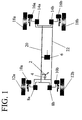
- Fig. 1 shows a schematic representation of a brake system from Brake-by-wire type, in the figure only for those following explanations necessary components are shown.
- the brake system has a brake pedal 2 with a sensor 4, which by a driver through a the foot pedal force applied 2 Converts braking request into an electric pedal signal S.
- the brake system has a Central processing unit 6, via computing units 8a and 8b Brake actuators 10a and 10b, the front axle wheels 12a and 12b are assigned.
- the brake system has Computing units 14a and 14b of brake actuators 16a and 16b, which are assigned to the rear axle wheels 18a and 18b.
- the braking system has a serial Data bus 20, via which the central unit 6 with the Computing units 8a, 8b, 14a and 14b can exchange data.
- the brake system also has a signal line 22, via which the pedal signal S from the sensor 4 to the Computing units 8a, 8b, 14a and 14b is transferable.
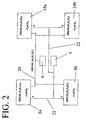
- the pedal signal S generated in the sensor 4 is transmitted via the separate signal line 22 to the computing units 8a, 8b, 14a and 14b.
- the "simultaneous" arrival of the pedal signal S at the computing units 8a, 8b, 14a and 14b is ensured by an analog or quasi-analog signal path between the sensor 4 and the individual computing units 8a, 8b, 14a and 14b.
- a braking force distribution key BS consisting of the components K 1 to K 4, is already stored in the individual computing units 8a, 8b, 14a and 14b.
- the individual components of the brake force distribution key BS indicate the relative braking force that would have to be applied to the corresponding brake actuator in the event of a braking process triggered by actuation of the brake pedal 2.
- a brake force distribution key could, for example, look like this: [45/100; 25/100; 20/100, 10/100]. This would mean that 45% on the wheel 12a and 25% on the wheel 12b 20% of the total braking force represented by the pedal signal S would be adjusted to the wheel 18a and 10% to the wheel 18b.
- the braking force F to be controlled on the assigned brake actuators 10a, 10b, 16a and 16b is calculated from the product of the pedal signal S and the corresponding component of the brake force distribution key.
- the absolute braking force F 1 is thus calculated from the product S and the component K 1 of the braking force distribution key BS, etc.
- the one stored in the computing units 8a, 8b, 14a and 14b Brake force distribution key BS is in time intervals replaced by a new brake force distribution key BS '.
- the new brake force distribution key BS ' is in the Central processing unit 6 based on the most varied Information calculated and via the serial data bus 20 to the computing units 8a, 8b, 14a and 14b simultaneously where he submits the old brake force distribution key BSercode.
- After saving the new brake force distribution key BS ' is the calculation of each Brake forces based on the new brake force distribution key BS 'made.
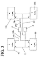
- the calculation of the individual brake forces F takes place in the computing units 8a, 8b, 14a and 14b in exactly the same way as has already been explained in connection with FIG. 2.
- the only difference from FIG. 2 is that the central unit 6 does not, as shown in FIG. 2, via a serial data bus 20, but via individual signal lines 24a, 24b, 24c and 24d with the corresponding computing units 8a, 8b, 14a and 14b is connected.
- a new brake force distribution key BS ' consisting of the components K 1 ' to K 4 ', is also calculated in the central unit 6 at intervals and the individual components of the brake force distribution key are now sent to the corresponding computing units via the corresponding signal lines 24a, 24b, 24c and 24d 8a, 8b, 14a and 14b transmitted.
- the simultaneous arrival of the components is ensured by the type of signal transmission on the signal lines 24a, 24b, 24c and 24d.
- the new components K 1 'to K 4 ' replace the stored components K1 to K4 of the old brake force distribution key BS in the corresponding computing units 8a, 8b, 14a and 14b, and from the time of the replacement, the new brake forces F are based on the new components K. 1 'to K 4 ' calculated.
Landscapes
- Engineering & Computer Science (AREA)
- Transportation (AREA)
- Mechanical Engineering (AREA)
- Braking Systems And Boosters (AREA)
- Regulating Braking Force (AREA)
Description
Die Erfindung betrifft ein Verfahren zum kontrollierten Bremsen eines Kraftfahrzeuges mit einer Bremsanlage, die unter anderem ein Bremspedal zur Erzeugung eines Pedalsignals, jeweils einen Bremsaktuator für jedes Rad des Kraftfahrzeuges und eine Zentraleinheit, die mit den Bremsaktuatoren verbunden ist und Informationen an diese übermitteln kann, enthält, bei dem jeder Bremsaktuator bei einem Bremsvorgang mit einer zuvor berechneten Bremskraft beaufschlagt wird. Die Erfindung betrifft ferner eine Bremsanlage für ein Kraftfahrzeug.The invention relates to a method for controlled Braking a motor vehicle with a brake system that under a brake pedal to generate a pedal signal, one brake actuator for each wheel of the motor vehicle and a central unit connected to the brake actuators is and can transmit information to them which each brake actuator during a braking operation with one before calculated braking force is applied. The invention also relates to a brake system for a motor vehicle.
In jüngster Vergangenheit sind für Kraftfahrzeuge, insbesondere für Personenkraftwagen, Bremsanlagen vom Brake-by-Wire Typ entwickelt worden. Eine derartige Bremsanlage ist beispielsweise aus der DE 40 22 671 A1 bekannt und verfügt über einen Bremswertgeber, der mit zwei Zentralmodulen verbunden ist, die ihrerseits über jeweils einen Datenbus mit zwei Radmodulen verbunden sind. Über die Datenbusse können die Zentralmodule und die ihnen zugeordneten Radmodule Daten im seriellen Betrieb austauschen.In the recent past, for automobiles, especially for passenger cars, brake systems by brake-by-wire Type has been developed. Such a brake system is known and has for example from DE 40 22 671 A1 via a brake value transmitter with two central modules is connected, which in turn with a data bus two wheel modules are connected. Via the data buses Central modules and the wheel modules assigned to them Exchange serial operation.
Mit Hilfe der aus der DE 40 22 671 A1 bekannten Bremsanlage wird ein Bremsvorgang im wesentlichen wie folgt durchgeführt. Der von einem Fahrer vorgegebene Bremswert wird über den Bremswertgeber den Zentralmodulen zugeleitet und hier zunächst in individuelle Bremswerte für die einzelnen Radmodule umgewandelt. Daraufhin werden die individuellen Bremswerte über die Datenbusse von den Zentralmodulen an die Radmodule weitergeleitet und auf Basis der individuellen Bremswerte wird von den Radmodulen der Bremsvorgang an dem jeweiligen Rad des Kraftfahrzeuges eingeleitet.With the help of the brake system known from DE 40 22 671 A1 a braking operation is carried out essentially as follows. The braking value specified by a driver is determined by the Brake value transmitter fed to the central modules and here first in individual braking values for the individual wheel modules converted. Then the individual braking values via the data buses from the central modules to the wheel modules forwarded and based on the individual braking values of the wheel modules of the braking process on the respective wheel of the Motor vehicle initiated.
Durch die Erzeugung individueller Bremswerte können beispielsweise die unterschiedlichen Radlasten, z.B. durch Kurvenfahrt und/oder Belastung oder die unterschiedlichen Temperaturen der Bremsen berücksichtigt werden, so daß eine überhitzte Bremse erkannt und ausgeregelt wird und Giermomente des Kraftfahrzeuges ausgeglichen werden können. Zur Berücksichtigung der Betriebsparameter der einzelnen Radbremsen müssen jedoch über die Datenbusse Daten von den einzelnen Radmodulen zu den Zentraleinheiten übertragen werden. Infolgedessen sind die Datenbusse zeitweise "belegt" und es können dann keine Daten für die Einleitung eines Bremsvorganges von den Zentralmodulen zu den Radmodulen übertragen werden. Es kommt dann zu einer unerwünschten Verzögerung des Bremsvorganges. Darüber hinaus ist nicht immer gewährleistet, daß die von den Zentralmodulen "abgeschickten" individuellen Bremswerte gleichzeitig an allen vier Radmodulen ankommen, so daß es aufgrund von Ungleichzeitigkeiten zu einem unerwünschten Schiefziehen des Kraftfahrzeuges kommen kann. Schließlich ist die aus der DE 40 22 671 A1 bekannte Bremsanlage insofern als unsicher zu bezeichnen, als das es bei einem Ausfall der Zentralmodule zu einem Totalausfall der Bremsanlage kommt, da in diesem Fall der vorgegebene Bremswert von den Zentralmodulen nicht mehr registriert und die individuellen Bremswerte von den Zentralmodulen nicht mehr an die einzelnen Radmodule weitergegeben werden. By generating individual braking values for example the different wheel loads, e.g. by Cornering and / or load or the different Temperatures of the brakes are taken into account, so that a overheated brake is detected and corrected and yaw moments of the motor vehicle can be compensated. to Taking into account the operating parameters of each However, wheel brakes must have data from the individual wheel modules to the central units become. As a result, the data buses are temporarily "occupied" and then no data for the initiation of a Braking process from the central modules to the wheel modules be transmitted. An undesirable result then occurs Deceleration of the braking process. In addition, it is not always ensures that the "sent" from the central modules individual braking values simultaneously on all four wheel modules arrive so that due to non-coincidence an undesirable pulling of the motor vehicle can. Finally, the one known from DE 40 22 671 A1 Brake system to be described as unsafe in that it in the event of a failure of the central modules, the Brake system comes because in this case the specified braking value no longer registered by the central modules and the individual braking values from the central modules no longer the individual wheel modules are passed on.
Aus der EP 0 439 559 B1 ist eine Anlage mit verteilten, untereinander über einen seriellen Datenbus kommunizierenden Modulen bekannt, mit der in einzelnen Modulen Befehle ohne Zeitverzug ausführbar sind. Dazu werden von einem Zentralmodul über den Datenbus zu einem beliebigen Zeitpunkt Befehle zu den anderen Modulen übermittelt, wo diese gespeichert werden. Die Aufforderung zur Durchführung des gespeicherten Befehls wird den Modulen über separate Datenleitungen zugeführt und der gespeicherte Befehl wird unmittelbar nach Empfang der Aufforderung ausgeführt.EP 0 439 559 B1 describes a system with distributed, communicating with each other via a serial data bus Known modules with which commands in individual modules without Delays are executable. To do this from a central module Commands to the transmitted to other modules, where they are saved. The Prompt to execute the saved command fed to the modules via separate data lines and the stored command is immediately after receiving the Executed prompt.
Die aus der EP 0 439 559 B1 bekannte Anlage ist jedoch zur Verwendung in Bremsanlagen vom Brake-by-Wire Typ nicht geeignet, da die Befehlsgenerierung in dem Zentralmodul, die Befehlsübermittlung zwischen dem Zentralmodul und den anderen Modulen und die Speicherung der festen Befehle in den Modulen automatisch abläuft und von dem Fahrer eines Kraftfahrzeuges nicht beeinflußbar ist. Bei einem Bremsvorgang handelt es sich aber gerade um einen Vorgang, der vom Fahrer durch geeignete Betätigung des Bremspedals situationsbedingt beeinflußt werden soll.The system known from EP 0 439 559 B1 is, however, for Not used in brake systems of the brake-by-wire type suitable because the command generation in the central module, the Command transmission between the central module and the others Modules and the storage of the fixed commands in the modules runs automatically and by the driver of a motor vehicle cannot be influenced. Braking is involved but it is precisely a process that the driver can use through suitable Actuation of the brake pedal can be influenced depending on the situation should.
Der Erfindung liegt die Aufgabe zugrunde, ein Verfahren zum kontrollierten Bremsen eines Kraftfahrzeuges zu schaffen, bei dem einerseits der Bremsvorgang möglichst unmittelbar nach Betätigung des Bremspedals eingeleitet wird und bei dem andererseits eine sichere Notbremsung des Kraftfahrzeuges auch dann noch möglich ist, wenn das oder die Zentraleinheiten der Bremsanlage ausfallen. Der Erfindung liegt ferner die Aufgabe zugrunde, eine Bremsanlage zur Durchführung des Verfahrens zu schaffen. The invention has for its object a method for to create controlled brakes of a motor vehicle at on the one hand, the braking process as immediately as possible Actuation of the brake pedal is initiated and at the on the other hand also safe emergency braking of the motor vehicle is still possible if that or the central units of the Brake system fail. The invention is also the object based on a brake system to carry out the method create.
Gemäß den kennzeichnenden Merkmalen des Anspruchs 1 wird die Aufgabe durch folgende Verfahrensschritte gelöst:
- jedem Bremsaktuator (10a, 10b), (16a, 16b) ist eine Recheneinheit zugeordnet (8a, 8b), (14a, 14b) zugeordnet, in der zu jedem Zeitpunkt ein aktueller Bremskraftverteilungsschlüssel (BS) bzw. zumindest eine Komponente (Ki) aus dem Bremskraftverteilungsschlüssel (BS), die dem entsprechenden Bremsaktuator (10a, 10b), (16a, 16b) aus dem Bremskraftverteilungsschlüssel (BS) zugeordnet wird, vorliegt und
- das Pedalsignal (S) wird direkt an die Recheneinheiten (8a, 8b), (14a, 14b) der Bremsaktuatoren (10a, 10b), (16a, 16b) geleitet und
- die Bremskraft wird in jeder der Recheneinheiten (8a, 8b), (14a, 14b) der einzelnen Bremsaktuatoren (10a, 10b), (16a und 16b) aus der Komponente (Ki) und einer Information (S), die dem Pedalsignal entspricht, berechnet und daß
- in zeitlichen Abständen in der Zentraleinheit (6) ein neuer Bremskraftverteilungsschlüssel (BS') berechnet wird und zumindest die einem bestimmten Bremsaktuator (10a, 10b), (16a, 16b) zugeordnete neue Komponente (Ki') an die entsprechende Recheneinheit (8a, 8b), (14a, 14b) des jeweiligen Bremsaktuators (10a, 10b), (16a, 16b) übermittelt wird und dort die alte Komponente (Ki) ersetzt.
- Each brake actuator (10a, 10b), (16a, 16b) is assigned an arithmetic unit (8a, 8b), (14a, 14b) in which a current brake force distribution key (BS) or at least one component (K i ) is available at any time. from the brake force distribution key (BS), which is assigned to the corresponding brake actuator (10a, 10b), (16a, 16b) from the brake force distribution key (BS), and
- the pedal signal (S) is passed directly to the computing units (8a, 8b), (14a, 14b) of the brake actuators (10a, 10b), (16a, 16b) and
- the braking force is in each of the computing units (8a, 8b), (14a, 14b) of the individual brake actuators (10a, 10b), (16a and 16b) from the component (K i ) and information (S) that corresponds to the pedal signal , calculated and that
- at intervals in the central unit (6) a new brake force distribution key (BS ') is calculated and at least the new component (K i ') assigned to a specific brake actuator (10a, 10b), (16a, 16b) is sent to the corresponding computing unit (8a, 8b), (14a, 14b) of the respective brake actuator (10a, 10b), (16a, 16b) is transmitted and there replaces the old component (K i ).
Der Bremskraftverteilungsschlüssel wird in der Zentraleinheit auf Basis der Fahrzeugdaten (z.B. Radstand, Schwerpunktlage und ähnlichem mehr), der Geschwindigkeit, des Lenkwinkels, der Querbeschleunigung und der Radlasten des Kraftfahrzeuges etc. berechnet. The brake force distribution key is in the central unit based on vehicle data (e.g. wheelbase, center of gravity and the like), the speed, the steering angle, the Lateral acceleration and the wheel loads of the motor vehicle etc. calculated.
Gemäß den kennzeichnenden Merkmalen des nebengeordneten Anspruchs 5 wird die Aufgabe bei einer Bremsanlage der eingangs genannten Art wie folgt gelöst:According to the distinctive features of the sibling Claim 5 is the task of a brake system solved as follows:
Jeder Bremsaktuator enthält unter anderem:
- einen überschreibbaren Speicher, in dem zu jedem Zeitpunkt ein aktueller Bremskraftverteilungsschlüssel (BS1) bzw. zumindest eine Komponente (Ki) aus dem Bremskraftverteilungsschlüssel (BS), die dem entsprechenden Bremsaktuator aus dem Bremskraftverteilungsschlüssel (BS1) zugeordnet ist, gespeichert ist und
- eine Recheneinheit, in der die Bremskraft an dem Bremsaktuator
aus dem Produkt der Komponente (Ki) und einer
Information (S), die dem Pedalsignal entspricht,
berechenbar ist.
Ferner ist die Zentraleinheit derart ausgebildet, daß in ihr ein neuer Bremskraftverteilungsschlüssel (BS') berechenbar ist, von dem zumindest die einem bestimmten Bremsaktuator zugeordnete neue Komponente (Ki') an den jeweiligen Bremsaktuator übermittelt wird und dort die gespeicherte Komponente (Ki) ersetzt.
- a rewritable memory in which a current brake force distribution key (BS1) or at least one component (K i ) from the brake force distribution key (BS), which is assigned to the corresponding brake actuator from the brake force distribution key (BS1), is stored at any time and
- a computing unit in which the braking force on the brake actuator can be calculated from the product of component (K i ) and information (S) that corresponds to the pedal signal.
Furthermore, the central unit is designed such that a new brake force distribution key (BS ') can be calculated in it, from which at least the new component (K i ') assigned to a specific brake actuator is transmitted to the respective brake actuator and the stored component (K i ) there replaced.
Der Grundgedanke der Erfindung ist darin zu sehen, daß in der Zentraleinheit ein relativer Bremskraftverteilungsschlüssel berechnet wird, was zu jedem beliebigen Zeitpunkt unabhängig von der Betätigung der Bremsanlage durch den Fahrer des Kraftfahrzeuges möglich ist. Dieser relative Bremskraftverteilungsschlüssel wird an die einzelnen Recheneinheiten der Bremsaktuatoren übermittelt und dort gespeichert, so daß dort zu jedem Zeitpunkt unabhängig von einem Bremsvorgang ein Bremskraftverteilungsschlüssel vorliegt. Bei einem Bremsvorgang wird aus dem Pedalsignal und der entsprechenden Komponente des relativen Bremskraftverteilungsschlüssels die absolute Bremskraft für den entsprechenden Bremsaktuator berechnet.The basic idea of the invention is to be seen in the fact that Central unit a relative brake force distribution key is calculated what is independent at any time from the driver's actuation of the braking system Motor vehicle is possible. This relative Brake force distribution key is sent to the individual Processing units of the brake actuators transmitted and there saved so that there at any time regardless of a braking force distribution key is present. When braking, the pedal signal and the corresponding component of the relative Brake force distribution key is the absolute braking force for the corresponding brake actuator is calculated.
Die mit der Erfindung erzielten Vorteile sind insbesondere darin zu sehen, daß Verzögerungen bei der Einleitung des Bremsvorganges vermieden werden, da das Pedalsignal über separate Signalleitungen direkt an die Bremsaktuatoren geleitet wird, und somit Verzögerung durch eine Überlastungdes Datenbusses etc. ausgeschlossen sind. Ferner liegt bei "Ankunft" des Pedalsignals immer ein aktueller Bremskraftverteilungsschlüssel in den Bremsaktuatoren vor, so daß die Berechnung unmittelbar erfolgen kann.The advantages achieved with the invention are particular to be seen in the fact that delays in the initiation of the Braking can be avoided because the pedal signal over separate signal lines directly to the brake actuators and thus delay due to an overload of the Data bus etc. are excluded. Also included "Arrival" of the pedal signal is always a current one Brake force distribution key in the brake actuators before, so that the calculation can take place immediately.
Ein weiterer Vorteil der Erfindung ist darin zu sehen, daß einem Schiefziehen des Kraftfahrzeuges wirksam vorgebeugt ist, da der Signalweg des Pedalsignals zu allen Bremsaktuatoren gleich ist und die Berechnung der Bremskraft in den einzelnen Bremsaktuatoren die gleiche Zeit in Anspruch nimmt und somit alle Bremsaktuatoren gleichzeitig aktiviert werden. Ferner ist die Bremsanlage sehr ausfallsicher, da auch bei einem Ausfall der Zentraleinheit ein Bremsvorgang "mit verminderter Qualität" auf Basis des direkt an die Bremsaktuatoren geleiteten Pedalsignals eingeleitet werden kann.Another advantage of the invention is that an effective prevention of the motor vehicle from being skewed, since the signal path of the pedal signal to all brake actuators is the same and the calculation of the braking force in each Brake actuators take the same time and therefore all brake actuators are activated at the same time. Furthermore is the brake system is very fail-safe, because even in the event of a failure the central unit a braking process "with reduced Quality "based directly on the brake actuators guided pedal signal can be initiated.
Gemäß einem Ausführungsbeispiel der Erfindung wird der Bremskraftverteilungsschlüssel in der Zentraleinheit periodisch berechnet und an die einzelnen Recheneinheiten der Bremsaktuatoren übermittelt. Die Frequenz der Berechnung des Bremskraftverteilungsschlüssels liegt vorzugsweise in einem Frequenzbereich von ca. 100 bis 1000 Hertz. Der Vorteil dieses Ausführungsbeispiels ist darin zu sehen, daß - insbesondere bei einer hohen Frequenz - immer ein sehr aktueller Bremskraftverteilungsschlüssel bzw. die entsprechende Komponente in den Bremsaktuatoren vorliegt. According to an embodiment of the invention, the Brake force distribution key in the central unit periodically calculated and sent to the individual computing units of the Brake actuators transmitted. The frequency of the calculation of the Brake force distribution key is preferably in one Frequency range from approx. 100 to 1000 Hertz. The advantage of this Embodiment can be seen in that - in particular at a high frequency - always a very current one Brake force distribution key or the corresponding one Component is present in the brake actuators.
Gemäß einem alternativen Ausführungsbeispiel der Erfindung wird ein neuer Bremskraftverteilungsschlüssel immer dann berechnet und an die einzelnen Recheneinheiten der Bremsaktuatoren übermittelt, wenn eine Änderung der Fahrsituation des Kraftfahrzeuges festgestellt wird, wenn sich also beispielsweise die Geschwindigkeit, der Lenkwinkel, die Querbeschleunigung etc. des Kraftfahrzeuges über ein vorgegebenes Maß hinaus verändern.According to an alternative embodiment of the invention is always a new brake force distribution key calculated and sent to the individual computing units of the Brake actuators are transmitted when there is a change in the Driving situation of the motor vehicle is determined when So for example the speed, the steering angle, the Lateral acceleration etc. of the motor vehicle via a Change the specified dimension.
Gemäß einer Weiterbildung der Erfindung nach Anspruch 4 wird
in der jeweiligen Recheneinheit des jeweiligen Bremsaktuator
der zuletzt gespeicherte Bremskraftverteilungsschlüssel bzw.
die zuletzt gespeicherte Komponente des Bremskraftverteilungsschlüssels,
die der Recheneinheit des
Bremsaktuators zugeordnet ist, durch einen festen vorgegebenen
Wert ersetzt, wenn nicht innerhalb eines vorgegebenen
Zeitraums ein neuer Bremskraftverteilungsschlüssel bzw. die
entsprechende Komponente an jeden Bremsaktuator übermittelt
worden ist. Diese Weiterbildung der Erfindung hat den Vorteil,
daß auch bei einem Ausfall der Zentraleinheit ein
Bremskraftverteilungsschlüssel in den Recheneinheiten der
einzelnen Bremsaktuatoren gespeichert werden kann, der noch
eine "qualitativ hochwertige" Notbremsung zuläßt.
Beispielsweise kann ein Bremskraftverteilungsschlüssel
gespeichert werden, der für die beiden Vorderräder jeweils
35/100 der einzuregelnden Bremskraft und die beiden
Hinterräder jeweils 15/100 der einzuregelnden Bremskraft
vorsieht. In diesem Fall entfallen 70 % der Bremskraft auf die
Vorderräder und nur 30 % der Bremskraft auf die Hinterräder,
so daß einem frühzeitigen Blockieren der Hinterräder, das in
der Regel zu einem gefährlichen "Ausbrechen" des
Kraftfahrzeuges führt, wirksam vorgebeugt ist. According to a development of the invention according to
Weitere Vorteile und ein Ausführungsbeispiel der Erfindung werden im Zusammenhang mit den nachstehenden Figuren erläutert, darin zeigt:
- Fig. 1
- eine Bremsanlage in schematischer Darstellung,
- Fig. 2
- ein Blockschaubild,
- Fig. 3
- ein Blockschaubild.
- Fig. 1
- a brake system in a schematic representation,
- Fig. 2
- a block diagram,
- Fig. 3
- a block diagram.
Fig. 1 zeigt in schematischer Darstellung eine Bremsanlage vom
Brake-by-Wire Typ, wobei in der Figur nur die für die
nachfolgenden Erläuterungen notwendigen Bestandteile
dargestellt sind. Die Bremsanlage verfügt über ein Bremspedal
2 mit einem Sensor 4, der den von einem Fahrer durch eine auf
das Bremspedal 2 einwirkende Fußkraft kundgetanen
Bremswunschin ein elektrisches Pedalsignal S umwandelt.
Darüber hinaus verfügt die Bremsanlage über eine
Zentraleinheit 6, über Recheneinheiten 8a und 8b der
Bremsaktuatoren 10a und 10b, die den Vorderachsrädern 12a und
12b zugeordnet sind. Entsprechend verfügt die Bremsanlage über
Recheneinheiten 14a und 14b der Bremsaktuatoren 16a und 16b,
die den Hinterachsrädern 18a und 18b zugeordnet sind.
Schließlich verfügt die Bremsanlage über einen seriellen
Datenbus 20, über den die Zentraleinheit 6 mit den
Recheneinheiten 8a, 8b, 14a und 14b Daten austauschen kann.
Darüber hinaus verfügt die Bremsanlage über eine Signalleitung
22, über die von dem Sensor 4 das Pedalsignal S zu den
Recheneinheiten 8a, 8b, 14a und 14b übertragbar ist.Fig. 1 shows a schematic representation of a brake system from
Brake-by-wire type, in the figure only for those
following explanations necessary components
are shown. The brake system has a
Die Funktion die in der Fig. 1 gezeigten Bremsanlage wird im
folgenden im Zusammenhang mit der Figur 2 näher erläutert. Bei
einem Bremsvorgang wird das in dem Sensor 4 erzeugte
Pedalsignal S über die separate Signalleitung 22 zu den
Recheneinheiten 8a, 8b, 14a und 14b übertragen. Die
"gleichzeitige" Ankunft des Pedalsignals S an den
Recheneinheiten 8a, 8b, 14a und 14b wird durch eine analoge
bzw. quasianaloge Signalstrecke zwischen dem Sensor 4 und den
einzelnen Recheneinheiten 8a, 8b, 14a und 14b sichergestellt.
In den einzelnenen Recheneinheiten 8a, 8b, 14a und 14b ist
bereits ein Bremskraftverteilungsschlüssel BS, bestehend aus
den Komponenten K1 bis K4 gespeichert. Die einzelnen
Komponenten des Bremskraftverteilungsschlüssels BS geben die
relative Bremskraft an, die bei einem durch Betätigung des
Bremspedals 2 ausgelösten Bremsvorgang an dem entsprechenden
Bremsaktuator einzusteuern wäre. (Ein Bremskraftverteilungsschlüssel
könnte beispielsweise wie folgt aussehen: [45/100;
25/100; 20/100, 10/100]. Dies würde bedeuten, daß bei einem
Bremsvorgang an dem Rad 12a 45%, an dem Rad 12b 25%, an dem
Rad 18a 20% und an dem Rad 18b 10% der gesamten durch das
Pedalsignal S dargestellten Bremskraft eingeregelt würden.)The function of the brake system shown in FIG. 1 is explained in more detail below in connection with FIG. 2. During a braking operation, the pedal signal S generated in the
In den einzelnen Recheneinheiten 8a, 8b, 14a und 14b wird die
an den zugeordneten Bremsaktuatoren 10a, 10b, 16a und 16b
einzusteuernde Bremskraft F aus dem Produkt des Pedalsignals S
und der entsprechenden Komponente des Bremskraftverteilungsschlüssels
berechnet. In der Recheneinheit 8a, die
dem Bremsaktuator 10a zugeordnet ist, der das Vorderrad 12a
bremst (siehe Fig. 1), wird die absolute Bremskraft F1 also
aus dem Produkt S und der Komponente K1 des Bremskraftverteilungsschlüssels
BS berechnet, usw.In the
Der in den Recheneinheiten 8a, 8b, 14a und 14b gespeicherte
Bremskraftverteilungsschlüssel BS wird in zeitlichen Abständen
durch einen neuen Bremskraftverteilungsschlüssel BS' ersetzt.
Der neue Bremskraftverteilungsschlüssel BS' wird in der
Zentraleinheit 6 auf Basis der unterschiedlichsten
Informationen berechnet und über den seriellen Datenbus 20
gleichzeitig an die Recheneinheiten 8a, 8b, 14a und 14b
übermittelt, wo er den alten Bremskraftverteilungsschlüssel
BSersetzt. Nach Speicherung des neuen Bremskraftverteilungsschlüssels
BS' wird die Berechnung der einzelnen
Bremskräfte auf Basis des neuen Bremskraftverteilungsschlüssels
BS' vorgenommen. (Der beispielhaft genannte Bremsverteilungsschlüssel
[45/100; 25/100; 20/100; 10/100] wird,
z.B. durch den neuen Bremskraftverteilungsschlüssel [20/100;
40/100; 15/100; 25/100] ersetzt, so daß nicht mehr die Räder
12a und 18a der rechten Kraftfahrzeugseite stärker gebremst
würden als die Räder 12b und 18b der linken Kraftfahrzeugseite,
sondern umgekehrt. Eine solche Änderung des Bremskraftverteilungsschlüssels
kann z.B. durch eine Änderung der
Fahrbahnoberfläche bedingt sein.)The one stored in the
Bei der in der Fig. 3 dargestellten Bremsanlage erfolgt die
Berechnung der einzelnen Bremskräfte F in den Recheneinheiten
8a, 8b, 14a und 14b genauso wie es bereits im Zusammenhang mit
der Fig. 2 erläutert worden ist. Der einzige Unterschied zu
der Fig. 2 besteht darin, daß die Zentraleinheit 6 nicht, wie
in der Fig. 2 gezeigt, über einen seriellen Datenbus 20,
sondern über einzelne Signalleitungen 24a, 24b, 24c und 24d
mit den entsprechenden Recheneinheiten 8a, 8b, 14a und 14b
verbunden ist. In der Zentraleinheit 6 wird ebenfalls in
zeitlichen Abständen ein neuer Bremskraftverteilungsschlüssel
BS', bestehend aus den Komponenten K1' bis K4' berechnet
und die einzelnen Komponenten des Bremskraftverteilungsschlüssels
werden nun über die entsprechenden Signalleitungen
24a, 24b, 24c und 24d an die entsprechenden Recheneinheiten
8a, 8b, 14a und 14b übermittelt. Die gleichzeitige Ankunft der
Komponenten wird durch die Art der Signalübertragung auf den
Signalleitungen 24a, 24b, 24c und 24d sichergestellt. Die
neuen Komponenten K1' bis K4' ersetzen in den
entsprechenden Recheneinheiten 8a, 8b, 14a und 14b die
gespeicherten Komponenten K1 bis K4 des alten
Bremskraftverteilungsschlüssels BS, und ab dem Zeitpunkt der
Ersetzung werden die neuen Bremskräfte F auf Basis der neuen
Komponenten K1' bis K4' berechnet. In the brake system shown in FIG. 3, the calculation of the individual brake forces F takes place in the
- 22
- Bremspedalbrake pedal
- 44
- Sensorsensor
- 66
- Zentraleinheitcentral processing unit
- 8a, 8b8a, 8b
-
Recheneinheiten der Bremsaktuatoren 10a, 10bComputing units of the
brake actuators - 10a, 10b10a, 10b
-
Bremsaktuatoren der Vorderachsräder 12a, 12bBrake actuators of the
front axle wheels - 12a, 12b12a, 12b
- Vorderachsräderfront axle wheels
- 14a, 14b14a, 14b
-
Recheneinheiten der Bremsaktuatoren 16a, 16bComputing units of the
brake actuators - 16a, 16b16a, 16b
- Bremsaktuatoren der HinterachsräderBrake actuators on the rear axle wheels
- 18a, 18b18a, 18b
- Hinterachsräderrear axle wheels
- 2020
- serieller Datenbusserial data bus
- 2222
-
Signalleitung von Sensor 4 zu Recheneinheiten
8a, 8b, 14a, 14bSignal line from
sensor 4 tocomputing units - 24a, 24b, 24c, 24d,24a, 24b, 24c, 24d,
-
Signalleitungen von der Zentraleinheit 6 zu den
Recheneinheiten 8a, 8b, 14a, 14bSignal lines from the
central unit 6 to theComputing units
Claims (5)
- A method for controlled braking of a motor vehicle with a brake system comprising, among others, a brake pedal (2) for producing a pedal signal (S), one brake actuator (10a, 10b), (16a, 16b) for each wheel (12a, 12b), (18a, 18b) of the motor vehicle, and a central unit (6) which is connected to the brake actuators (10a, 10b), (16a, 16b) and can transmit information to the actuators, wherein each brake actuator (10a,10b), (16a, 16b) is acted upon by a previously computed braking force, a computing unit (8a, 8b), (14a, 14b) being associated with each brake actuator (10a, 10b), (16a, 16b),
characterized in that
in the computing unit (8a, 8b), (14a, 14b) associated with each brake actuator (10a, 10b), (16a, 16b), there prevails at any point of time a current braking-force distribution key (BS) and/or at least one component (Ki) from said braking-force distribution key (BS) which is associated with the corresponding brake actuator (10a, 10b), (16a, 16b) from the braking-force distribution key (BS), and
the pedal signal (S) is sent directly to the computing units (8a, 8b), (14a, 14b) of the brake actuators (10a, 10b), (16a, 16b), and
the brake force in each of the computing units (8a, 8b), (14a, 14b) of the individual brake actuators (10a, 10b), (16a and 16b) is calculated from the component (Ki) from the braking-force distribution key (BS) and an information (S) that corresponds to the pedal signal, and that
a new braking-force distribution key (BS') is computed at time intervals in the central unit (6), and at least the new component (Ki') assigned to a defined brake actuator (10a, 10b), (16a, 16b) is transmitted to the corresponding computing unit (8a, 8b), (14a, 14b) of the respective brake actuator (10a, 10b), (16a, 16b) and there replaces the old component (Ki) . - Method for controlled braking of a motor vehicle as claimed in claim 1,
characterized in that a new braking-force distribution key (BS') is periodically computed. - Method for controlled braking of a motor vehicle as claimed in claim 1,
characterized in that a new braking-force distribution key (BS') is computed when a change of the driving situation of the motor vehicle is determined. - Method for controlled braking of a motor vehicle as claimed in any one of claims 1 to 3,
characterized in that unless at least the new component (Ki') is transmitted to the respective computing unit (8a, 8b), (14a, 14b) of the respective brake actuator (10a, 10b), (16a, 16b) within a predetermined time span, the last stored component (Ki) in the computing unit is replaced by an invariably preset value. - Electrical brake system for a motor vehicle comprising, among others, a brake pedal (2), one brake actuator (10a, 10b), (16a, 16b) for each wheel (12a, 12b), (18a, 18b) of the motor vehicle, which actuator is acted upon by a previously computed braking force during a braking operation, as well as a central unit (6) which is connected to the brake actuators (10a, 10b), (16a, 16b) and can transmit information to these, as well as a computing unit (8a, 8b), (14a, 14b) being associated with each brake actuator (10a, 10b), (16a, 16b),
characterized in that each brake actuator (10a, 10b), (16a, 16b) comprises among others:an overwrite memory wherein at any point of time a current braking-force distribution key (BS) and/or at least one component (Ki) from said braking-force distribution key (BS) is stored, said component being associated with the corresponding brake actuator (10a, 10b), (16a, 16b) from the braking-force distribution key (BS), whereinthe braking force at the brake actuator (10a, 10b), (16a, 16b) may be computed in the computing unit (8a, 8b), (14a, 14b) from the product of the component (Ki) and an information (S) which corresponds to a pedal signal,and the central unit is so designed that in it a new braking-force distribution key (BS') can be computed, from which at least the new component (Ki') assigned to a determined brake actuator (10a, 10b), (16a, 16b) is transmitted to the respective brake actuator (10a, 10b), (16a, 16b) and there replaces the stored component (Ki).
Applications Claiming Priority (2)
| Application Number | Priority Date | Filing Date | Title |
|---|---|---|---|
| DE19617285 | 1996-04-30 | ||
| DE19617285A DE19617285C1 (en) | 1996-04-30 | 1996-04-30 | Operation of electrical brake system of motor vehicle |
Publications (3)
| Publication Number | Publication Date |
|---|---|
| EP0805084A2 EP0805084A2 (en) | 1997-11-05 |
| EP0805084A3 EP0805084A3 (en) | 1998-05-20 |
| EP0805084B1 true EP0805084B1 (en) | 2003-03-26 |
Family
ID=7792891
Family Applications (1)
| Application Number | Title | Priority Date | Filing Date |
|---|---|---|---|
| EP97106867A Expired - Lifetime EP0805084B1 (en) | 1996-04-30 | 1997-04-25 | Procedure for the controlled braking of a vehicle |
Country Status (3)
| Country | Link |
|---|---|
| US (1) | US5902019A (en) |
| EP (1) | EP0805084B1 (en) |
| DE (2) | DE19617285C1 (en) |
Families Citing this family (15)
| Publication number | Priority date | Publication date | Assignee | Title |
|---|---|---|---|---|
| DE19733379B4 (en) * | 1997-08-01 | 2005-03-10 | Bosch Gmbh Robert | Device for controlling a brake system |
| EP1024983A1 (en) * | 1997-10-29 | 2000-08-09 | Continental Teves AG & Co. oHG | Device and method for controlling a braking system |
| US6317675B1 (en) * | 1997-11-22 | 2001-11-13 | Continental Teves Ag & Co., Ohg | Electromechanical brake system |
| DE19828331C1 (en) * | 1998-06-25 | 2000-03-02 | Continental Ag | Method for operating an electromechanical brake system |
| JP2000225935A (en) * | 1999-02-03 | 2000-08-15 | Toyota Motor Corp | Electric control brake system |
| SE516469C2 (en) * | 2000-02-14 | 2002-01-15 | Scania Cv Ab | Device for ensuring the operation of a braking device for a vehicle |
| DE10154425A1 (en) * | 2001-11-06 | 2003-05-15 | Continental Teves Ag & Co Ohg | Process for controlling the braking force of vehicle brake systems of the brake-by-wire type |
| FR2867435B1 (en) * | 2004-03-09 | 2007-11-09 | Peugeot Citroen Automobiles Sa | ACTIVE BRAKING SYSTEM FOR MOTOR VEHICLE |
| DE102007013511A1 (en) * | 2007-03-21 | 2008-09-25 | Audi Ag | Motor vehicle with an X-by-wire system and method for operating an X-by-wire system of a motor vehicle |
| JP6565388B2 (en) * | 2015-07-02 | 2019-08-28 | 三菱自動車工業株式会社 | Electric brake device |
| JP6605248B2 (en) * | 2015-07-27 | 2019-11-13 | Ntn株式会社 | Friction brake system |
| GB201515813D0 (en) * | 2015-09-07 | 2015-10-21 | Jaguar Land Rover Ltd | Controller for a braking system |
| US10131336B2 (en) | 2016-09-26 | 2018-11-20 | Bendix Commercial Vehicle Systems Llc | System and method for braking a vehicle |
| DE102022209930A1 (en) * | 2022-09-21 | 2024-03-21 | Continental Automotive Technologies GmbH | Braking system with flexible architecture and method for operating such a braking system |
| DE102023210218A1 (en) * | 2023-10-18 | 2025-04-24 | Robert Bosch Gesellschaft mit beschränkter Haftung | Braking system for a motor vehicle and a corresponding method for operating a braking system |
Family Cites Families (9)
| Publication number | Priority date | Publication date | Assignee | Title |
|---|---|---|---|---|
| DE3927968A1 (en) * | 1989-08-24 | 1991-02-28 | Bosch Gmbh Robert | METHOD FOR TRANSMITTING DATA OVER A SERIAL DATA BUS IN DISTRIBUTED SYSTEMS |
| DE4022671A1 (en) * | 1990-07-17 | 1992-01-23 | Wabco Westinghouse Fahrzeug | ELECTRONIC BRAKE SYSTEM FOR ROAD VEHICLES |
| DE4030724B4 (en) * | 1990-09-28 | 2005-05-04 | Robert Bosch Gmbh | Anti-lock control system |
| DE69431862T2 (en) * | 1993-09-22 | 2003-07-10 | Aisin Seiki K.K., Kariya | Radbremsdrucksteuergerät |
| DE4339570B4 (en) * | 1993-11-19 | 2004-03-04 | Robert Bosch Gmbh | Electronic braking system |
| US5772289A (en) * | 1994-10-11 | 1998-06-30 | Nissan Diesel Co., Ltd. | Vehicle braking force controller |
| US5694321A (en) * | 1994-11-25 | 1997-12-02 | Itt Automotive Europe Gmbh | System for integrated driving stability control |
| US5732379A (en) * | 1994-11-25 | 1998-03-24 | Itt Automotive Europe Gmbh | Brake system for a motor vehicle with yaw moment control |
| DE19500837C2 (en) * | 1995-01-13 | 1999-10-14 | Continental Ag | Brake force distributor due to wheel speed |
-
1996
- 1996-04-30 DE DE19617285A patent/DE19617285C1/en not_active Expired - Fee Related
-
1997
- 1997-04-25 EP EP97106867A patent/EP0805084B1/en not_active Expired - Lifetime
- 1997-04-25 DE DE59709593T patent/DE59709593D1/en not_active Expired - Lifetime
- 1997-04-30 US US08/841,379 patent/US5902019A/en not_active Expired - Lifetime
Also Published As
| Publication number | Publication date |
|---|---|
| EP0805084A2 (en) | 1997-11-05 |
| EP0805084A3 (en) | 1998-05-20 |
| DE59709593D1 (en) | 2003-04-30 |
| US5902019A (en) | 1999-05-11 |
| DE19617285C1 (en) | 1997-08-21 |
Similar Documents
| Publication | Publication Date | Title |
|---|---|---|
| EP4048565B1 (en) | Braking system for a motor vehicle | |
| EP0805084B1 (en) | Procedure for the controlled braking of a vehicle | |
| EP3529117B2 (en) | System comprising separate control units for the actuation units of an electric parking brake | |
| EP3529118B2 (en) | System comprising separate control units for the actuation units of an electric parking brake | |
| EP2183136B1 (en) | Brake system for a vehicle and a method for the operation of a brake system for a vehicle | |
| EP4071012B1 (en) | Braking system for an autonomous vehicle | |
| EP0426959B1 (en) | Braking method of a vehicle provided with pressure actuated brakes | |
| EP3802244B1 (en) | Control unit and method for controlling a brake actuator of a vehicle, particularly of a railway vehicle | |
| WO2021197554A1 (en) | Brake system | |
| WO2009152981A1 (en) | Brake system and method for controlling a vehicle brake | |
| DE19604391A1 (en) | Braking system for vehicle | |
| WO2005082694A1 (en) | Redundant brake control system for a vehicle | |
| EP2162328B2 (en) | Automatic parking brake with slip controller | |
| EP1259861B1 (en) | Device and method for the electromotive regulation of an actuating device | |
| DE19835352C1 (en) | Brake and / or chassis control device | |
| EP1006032A2 (en) | Vehicle wheel unit | |
| EP3419872B1 (en) | Method and device for the open-loop or closed-loop control of a braking system | |
| EP1233893A1 (en) | Method and device for controlling a brake system | |
| DE102019108620B4 (en) | Method and control unit for controlling a steering brake function for a vehicle and braking system for a vehicle | |
| DE102004058996A1 (en) | Method and driving function system for transferring safety-relevant driving functions of a vehicle into the safe state | |
| DE102023122197A1 (en) | Decentralized control system for a motor vehicle braking system, motor vehicle braking system and motor vehicle | |
| EP4288311B1 (en) | Method for operating a control system of a vehicle with a steering brake function and traction control system | |
| WO2024114870A1 (en) | Electromechanical brake system for a motor vehicle with yawing momentum restriction | |
| DE102020111402A1 (en) | Emergency braking of a motor vehicle by means of a dual clutch transmission | |
| EP0891274B1 (en) | Braking system with electronic braking force distribution |
Legal Events
| Date | Code | Title | Description |
|---|---|---|---|
| PUAI | Public reference made under article 153(3) epc to a published international application that has entered the european phase |
Free format text: ORIGINAL CODE: 0009012 |
|
| AK | Designated contracting states |
Kind code of ref document: A2 Designated state(s): DE FR GB IT |
|
| PUAL | Search report despatched |
Free format text: ORIGINAL CODE: 0009013 |
|
| AK | Designated contracting states |
Kind code of ref document: A3 Designated state(s): DE FR GB IT |
|
| 17P | Request for examination filed |
Effective date: 19981120 |
|
| GRAG | Despatch of communication of intention to grant |
Free format text: ORIGINAL CODE: EPIDOS AGRA |
|
| 17Q | First examination report despatched |
Effective date: 20020605 |
|
| RAP1 | Party data changed (applicant data changed or rights of an application transferred) |
Owner name: CONTINENTAL TEVES AG & CO. OHG |
|
| GRAG | Despatch of communication of intention to grant |
Free format text: ORIGINAL CODE: EPIDOS AGRA |
|
| GRAH | Despatch of communication of intention to grant a patent |
Free format text: ORIGINAL CODE: EPIDOS IGRA |
|
| GRAH | Despatch of communication of intention to grant a patent |
Free format text: ORIGINAL CODE: EPIDOS IGRA |
|
| GRAA | (expected) grant |
Free format text: ORIGINAL CODE: 0009210 |
|
| AK | Designated contracting states |
Designated state(s): DE FR GB IT |
|
| PG25 | Lapsed in a contracting state [announced via postgrant information from national office to epo] |
Ref country code: GB Free format text: LAPSE BECAUSE OF FAILURE TO SUBMIT A TRANSLATION OF THE DESCRIPTION OR TO PAY THE FEE WITHIN THE PRESCRIBED TIME-LIMIT Effective date: 20030326 |
|
| REG | Reference to a national code |
Ref country code: GB Ref legal event code: FG4D Free format text: NOT ENGLISH |
|
| REF | Corresponds to: |
Ref document number: 59709593 Country of ref document: DE Date of ref document: 20030430 Kind code of ref document: P |
|
| GBV | Gb: ep patent (uk) treated as always having been void in accordance with gb section 77(7)/1977 [no translation filed] |
Effective date: 20030326 |
|
| ET | Fr: translation filed | ||
| PLBE | No opposition filed within time limit |
Free format text: ORIGINAL CODE: 0009261 |
|
| STAA | Information on the status of an ep patent application or granted ep patent |
Free format text: STATUS: NO OPPOSITION FILED WITHIN TIME LIMIT |
|
| 26N | No opposition filed |
Effective date: 20031230 |
|
| PGFP | Annual fee paid to national office [announced via postgrant information from national office to epo] |
Ref country code: FR Payment date: 20140422 Year of fee payment: 18 Ref country code: IT Payment date: 20140430 Year of fee payment: 18 Ref country code: DE Payment date: 20140430 Year of fee payment: 18 |
|
| REG | Reference to a national code |
Ref country code: DE Ref legal event code: R119 Ref document number: 59709593 Country of ref document: DE |
|
| PG25 | Lapsed in a contracting state [announced via postgrant information from national office to epo] |
Ref country code: IT Free format text: LAPSE BECAUSE OF NON-PAYMENT OF DUE FEES Effective date: 20150425 Ref country code: DE Free format text: LAPSE BECAUSE OF NON-PAYMENT OF DUE FEES Effective date: 20151103 |
|
| REG | Reference to a national code |
Ref country code: FR Ref legal event code: ST Effective date: 20151231 |
|
| PG25 | Lapsed in a contracting state [announced via postgrant information from national office to epo] |
Ref country code: FR Free format text: LAPSE BECAUSE OF NON-PAYMENT OF DUE FEES Effective date: 20150430 |