EP0805068A2 - Roof rails for vehicles - Google Patents
Roof rails for vehicles Download PDFInfo
- Publication number
- EP0805068A2 EP0805068A2 EP97100175A EP97100175A EP0805068A2 EP 0805068 A2 EP0805068 A2 EP 0805068A2 EP 97100175 A EP97100175 A EP 97100175A EP 97100175 A EP97100175 A EP 97100175A EP 0805068 A2 EP0805068 A2 EP 0805068A2
- Authority
- EP
- European Patent Office
- Prior art keywords
- support plate
- roof
- wall
- spar
- support
- Prior art date
- Legal status (The legal status is an assumption and is not a legal conclusion. Google has not performed a legal analysis and makes no representation as to the accuracy of the status listed.)
- Granted
Links
Images


Classifications
-
- B—PERFORMING OPERATIONS; TRANSPORTING
- B60—VEHICLES IN GENERAL
- B60R—VEHICLES, VEHICLE FITTINGS, OR VEHICLE PARTS, NOT OTHERWISE PROVIDED FOR
- B60R9/00—Supplementary fittings on vehicle exterior for carrying loads, e.g. luggage, sports gear or the like
- B60R9/04—Carriers associated with vehicle roof
Definitions
- the invention relates to a roof rail for vehicles with a spar and support feet at the spar ends, which can be fastened to a vehicle roof and support the spar in a position spaced from the vehicle roof, each support foot consisting of an injection molded plastic body, a stiffening body and a stiffening body covering cap body.
- a support foot for a roof rail which consists of two composite injection molded plastic bodies. At least one of the plastic bodies should have internal cutouts, which are all open to the same long side and closed by the other plastic body. Whether such a support foot meets the stability requirements seems at least doubtful.
- DE 35 39 449 A1 relates to a connection of light metal profiles with connecting elements and shows a support foot of a roof rail connected to a spar.
- the support leg consists of a plastic injection molded part with a bent round bolt embedded therein as a stiffening body. Whether a round bolt embedded in the injection molding meets the stability requirements can suffice, because with the support foot it seems at least disadvantageous that a stiffening body has to be inserted into the mold cavity of an injection molding device before it is injection molded.
- a roof rail with an injection molded plastic support foot with a stiffening body embedded therein has also become known from DE 43 21 537 A1.
- the stiffening body has a three-part structure, which is disadvantageous for the production but also a sheet metal blank which can be loaded over the high edge, which has a positive effect on the stability of the support foot.
- inlay work must also be carried out prior to injection molding, with a correspondingly large production outlay.
- the invention is based on the object of creating a supporting foot for the latter, which is to be distinguished by low weight, high stability and particularly simple and inexpensive to produce.
- the roof rails now have a support leg which is composed of three parts, each of which is particularly simple and inexpensive to manufacture and can be connected to the other two parts.
- the plastic body can be easily manufactured without insert parts, which enables short cycle times during manufacture and is desirable for mass-produced items.
- Only the stiffening body stabilizing the support leg is made of metal, with a sheet metal blank having a special shape, e.g. B. can easily be obtained by using a follow-up tool.
- a deformed sheet metal blank is a particularly inexpensive component, so that the support leg is all in all very inexpensive to manufacture and also has the advantage of high resilience. Later recycling is favored by the fact that the parts of the support leg can be easily separated from each other.
- Fig. 1 shows the roof panel 1 of a vehicle with a roof rack arranged thereon.
- the roof rack is formed from two roof rails, consisting of support feet 2 and spars 3 as well as from cross beams 4, indicated only by dash-dotted lines, which are attached to the spars 3.
- the roof rails extend at least approximately parallel to one another and run in the direction of travel of the vehicle.
- Each support leg 2 consists essentially of a plastic body 5, a stiffening body 6 and a cap body 7.
- the plastic body 5 has a support plate 8, which is supported on the roof plate 1. Adjoining the support plate 8 in the axial direction is an arcuate first wall 9, which ends at an end wall 10 oriented perpendicular to the support plate 8. A pin 11 which can be inserted into a spar end extends from the end wall 10. The pin 11 has a first axially continuous groove 12 which is open at the top and a second groove 13 which is open at the top and runs parallel to this. Further axially continuous grooves 14 give the pin 11 spring properties in the radial direction to the wobble-free mounting in the spar 3. From the free end the support plate 8 to the end wall 10 runs with the first wall 9 a soft arcuate transition side wall 15 so that the plastic body 5 has an L-shaped cross section.
- the plastic body 5 also has an undercut nose 16 on the free end region of the pin 11, which nose can snap into a spar opening 17.
- a peg 18 formed on the first wall 9 serves to fix the stiffening body 6 on the plastic body 5, while holes 19 in the support plate 8 are intended to fix the cap body 7.
- a cuboid extension 20 is formed on the underside of the support plate 8.
- a bore extends through the support plate 8 and the extension 20 for the passage of a fastening screw 21.
- a metal bushing 22 is arranged within the bore, which counteracts a flow behavior of the plastic body 5 under load.
- the stiffening body 6 is an elongated molded part formed from a sheet metal blank with a U-shaped cross section over almost the entire length. Only at one end region 23 do the legs 24 lie against one another without a gap, while the legs 24 are otherwise connected to one another via a web. An opening 25 in the stiffening body 6 serves for the passage of the pin 18 on the plastic body 5 and a bore 26 for the passage of the fastening screw 21.
- the stiffening body 6 is connected to the plastic body 5 by simply placing it on.
- the end region 23 is supported in the groove 12, the other end region on the support plate 8 and the rest of the region on the first wall 9.
- the pin 18 passes through the opening 25, it being possible to provide the pin 18 with a mushroom head (not shown) for the purpose of producing a clip connection. However, it is also conceivable to form a rivet head on the pin 18 by thermal action.
- the cap body 7 is connected to the plastic body 5 in order to cover the stiffening body 6 and to give the support foot 2 a solid appearance.
- the cap body 7, preferably a plastic injection molded part, is adapted to the shape of the plastic body 5 and has at one end an extension 27 which is to be inserted into the groove 13 on the pin 11.
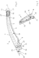
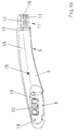
- the cap body 7 is fixed after the mounting of the support foot 2 on the spar 3, which is shown particularly clearly in FIG. 2.
- the cap body 7 has a clip element 28 for engaging in a hole 19 on the plastic body 5. If necessary, further clip connections must be provided.
Abstract
Description
Die Erfindung bezieht sich auf eine Dachreling für Fahrzeuge mit einem Holm und Stützfüßen an den Holmenden, die an einem Fahrzeugedach befestigbar sind und den Holm in einer vom Fahrzeugdach beabstandeten Position tragen, wobei jeder Stützfuß aus einem spritzgegossenen Kunststoffkörper, einem Versteifungskörper und aus einem den Versteifungskörper abdeckenden Kappenkörper besteht.The invention relates to a roof rail for vehicles with a spar and support feet at the spar ends, which can be fastened to a vehicle roof and support the spar in a position spaced from the vehicle roof, each support foot consisting of an injection molded plastic body, a stiffening body and a stiffening body covering cap body.
Durch die DE 32 30 346 A1 ist ein Stützfuß für eine Dachreling bekanntgeworden, der aus zwei zusammengesetzten spritzgegossenen Kunststoffkörpern besteht. Zumindest einer der Kunststoffkörper soll innere Aussparungen besitzen, die alle zur gleichen Längsseite hin offen und durch den anderen Kunststoffkörper geschlossen sind. Ob ein solcher Stützfuß den Stabilitätsanforderungen genügt, erscheint zumindest zweifelhaft.From DE 32 30 346 A1 a support foot for a roof rail has become known, which consists of two composite injection molded plastic bodies. At least one of the plastic bodies should have internal cutouts, which are all open to the same long side and closed by the other plastic body. Whether such a support foot meets the stability requirements seems at least doubtful.
Die DE 35 39 449 A1 bezieht sich auf eine Verbindung von Leichtmetallprofilen mit Anschlußelementen und zeigt einen mit einem Holm verbundenen Stützfuß einer Dachreling. Der Stützfuß besteht aus einem Kunststoff-Spritzgußteil mit einem darin eingelagerten gebogenen Rundbolzen als Versteifungskörper. Ob ein im Spritzguß eingelagerter Rundbolzen den Stabilitätsanforderungen zu genügen vermag, kann dahingestellt sein, denn bei dem Stützfuß erscheint es zumindest nachteilig, daß vor dem Spritzgießen desselben ein Versteifungskörper in das Formnest einer Spritzgießvorrichtung einzulegen ist.DE 35 39 449 A1 relates to a connection of light metal profiles with connecting elements and shows a support foot of a roof rail connected to a spar. The support leg consists of a plastic injection molded part with a bent round bolt embedded therein as a stiffening body. Whether a round bolt embedded in the injection molding meets the stability requirements can suffice, because with the support foot it seems at least disadvantageous that a stiffening body has to be inserted into the mold cavity of an injection molding device before it is injection molded.
Eine Dachreling mit einem spritzgegossenen Stützfuß aus Kunststoff mit einem darin eingelagerten Versteifungskörper ist ferner durch die DE 43 21 537 A1 bekanntgeworden. Der Versteifungskörper weist einen dreiteiligen Aufbau auf, was nachteilig für die Herstellung ist aber auch einen über die hohe Kante belastbaren Blechzuschnitt, was sich positiv auf die Stabilität des Stützfußes auswirkt. Andererseits muß aber auch beim Stützfuß der in dieser Druckschrift beschriebenen Art Einlegearbeit vor dem Spritzgießen geleistet werden mit einem entsprechend großen herstellungstechnischen Aufwand.A roof rail with an injection molded plastic support foot with a stiffening body embedded therein has also become known from DE 43 21 537 A1. The stiffening body has a three-part structure, which is disadvantageous for the production but also a sheet metal blank which can be loaded over the high edge, which has a positive effect on the stability of the support foot. On the other hand, in the case of the support leg of the type described in this document, inlay work must also be carried out prior to injection molding, with a correspondingly large production outlay.
Der Erfindung liegt nun ausgehend von einer Dachreling der eingangs genannten Art die Aufgabe zugrunde, für diese einen Stützfuß zu schaffen, der sich durch geringes Gewicht, hohe Stabilität und besonders einfache und kostengünstige Herstellbarkeit auszeichnen soll.Starting from a roof railing of the type mentioned, the invention is based on the object of creating a supporting foot for the latter, which is to be distinguished by low weight, high stability and particularly simple and inexpensive to produce.
Diese Aufgabe wird erfindungsgemäß mit den im Anspruch 1 angegebenen Merkmalen gelöst, während in den Unteransprüchen vorteilhafte Weiterbildungen und zweckmäßige Ausgestaltungen der Erfindung angegeben sind.This object is achieved according to the invention with the features specified in claim 1, while advantageous further developments and expedient refinements of the invention are specified in the subclaims.
Die Dachreling weist nunmehr einen Stützfuß auf, der aus drei Teilen zusammengesetzt ist, von denen jedes einzelne besonders einfach und kostengünstig herstellbar und mit den jeweils anderen beiden Teilen zu verbinden ist. Der Kunststoffkörper ist ohne Einlegeteile problemlos zu fertigen, was bei der Herstellung kurze Taktzeiten ermöglicht und bei Massenartikeln wünschenswert ist. Gleiches gilt für die Herstellung des Kappenkörpers, der bevorzugterweise ebenfalls ein Kunststoff-Spritzling ist. Lediglich der den Stützfuß stabilisierende Versteifungskörper besteht aus Metall, wobei ein Blechzuschnitt eine besondere Formgebung, z. B. durch den Einsatz eines Folgewerkzeugs problemlos erhalten kann. Natürlich ist ein verformter Blechzuschnitt ein besonders preiswertes Bauteil, so daß der Stützfuß alles in allem sehr kostengünstig herzustellen ist und zudem den Vorteil einer hohen Belastbarkeit aufweist. Ein späteres Recyceln wird dadurch begünstigt, daß die Teile des Stützfußes problemlos sortenrein voneinander getrennt werden können.The roof rails now have a support leg which is composed of three parts, each of which is particularly simple and inexpensive to manufacture and can be connected to the other two parts. The plastic body can be easily manufactured without insert parts, which enables short cycle times during manufacture and is desirable for mass-produced items. The same applies to the production of the cap body, which is preferably also a plastic molding. Only the stiffening body stabilizing the support leg is made of metal, with a sheet metal blank having a special shape, e.g. B. can easily be obtained by using a follow-up tool. Of course, a deformed sheet metal blank is a particularly inexpensive component, so that the support leg is all in all very inexpensive to manufacture and also has the advantage of high resilience. Later recycling is favored by the fact that the parts of the support leg can be easily separated from each other.
Ein Ausführungsbeispiel der Erfindung wird im folgenden anhand der Zeichnungen näher erläutert und es zeigen:
- Fig. 1
- eine Dachreling mit Stützfüßen und Holmen,
- Fig. 2
- eine Seitenansicht eines Stützfußes,
- Fig. 3
- eine Stirnansicht eines Stützfußes und
- Fig. 4
- eine Explosionsdarstellung eines Stützfußes
- Fig. 4a
- eine Einzelheit des Stützfußes.
- Fig. 1
- a roof rail with support feet and spars,
- Fig. 2
- a side view of a support leg,
- Fig. 3
- a front view of a support foot and
- Fig. 4
- an exploded view of a support leg
- Fig. 4a
- a detail of the support leg.
Fig. 1 läßt das Dachblech 1 eines Fahrzeugs mit einem darauf angeordneten Dachlastenträger erkennen. Der Dachlastenträger wird aus zwei Dachrelings, bestehend aus Stützfüßen 2 und Holmen 3 sowie aus lediglich strichpunktiert angedeuteten Querträgern 4, die an den Holmen 3 befestigt sind, gebildet. Die Dachrelings erstrecken sich zumindest annähernd parallel zueinander und verlaufen in Fahrtrichtung des Fahrzeugs.Fig. 1 shows the roof panel 1 of a vehicle with a roof rack arranged thereon. The roof rack is formed from two roof rails, consisting of
Jeder Stützfuß 2 besteht im wesentlichen aus einem Kunststoffkörper 5, einem Versteifungskörper 6 und einem Kappenkörper 7.Each
Der Kunststoffkörper 5 weist eine Auflageplatte 8 auf, die sich auf dem Dachblech 1 abstützt. An die Auflageplatte 8 schließt sich in axialer Richtung eine bogenförmig ansteigende erste Wand 9 an, die an einer senkrecht zur Auflageplatte 8 ausgerichtete Stirnwand 10 endet. Von der Stirnwand 10 geht ein in ein Holmende einführbarer Zapfen 11 aus. Der Zapfen 11 besitzt eine erste axial durchlaufende und nach oben offene Nut 12 und eine zu dieser parallel verlaufende zweite nach oben offene Nut 13. Weitere axial durchlaufende Nuten 14 verleihen dem Zapfen 11 Federungseigenschaften in radialer Richtung zur wackelfreien Halterung im Holm 3. Vom freien Ende der Auflageplatte 8 bis zur Stirnwand 10 verläuft eine mit der ersten Wand 9 einen weichen bogenförmigen Übergang bildende Seitenwand 15, so daß der Kunststoffkörper 5 einen L-förmigen Querschnitt besitzt. Der Kunststoffkörper 5 weist ferner am freien Endbereich des Zapfens 11 eine hinterschnittene Nase 16 auf, die in eine Holmöffnung 17 einzurasten vermag. Ein auf der ersten Wand 9 angeformter Zapfen 18 dient zum Festlegen des Versteifungskörpers 6 am Kunststoffkörper 5, während Löcher 19 in der Auflageplatte 8 zur Festlegung des Kappenkörpers 7 bestimmt sind.The
An der Unterseite der Auflageplatte 8 ist ein quaderförmiger Ansatz 20 angeformt. Durch die Auflageplatte 8 und dem Ansatz 20 erstreckt sich eine Bohrung zum Durchführen einer Befestigungsschraube 21. Innerhalb der Bohrung ist eine Metallbuchse 22 angeordnet, die einem Fließverhalten des Kunststoffkörpers 5 unter Belastung entgegenwirkt.A
Der Versteifungskörper 6 ist ein langgestrecktes aus einem Blechzuschnitt gebildetes Formteil mit einem U-förmigen Querschnitt über nahezu die gesamte Länge. Lediglich an einem Endbereich 23 liegen die Schenkel 24 abstandsfrei aneinander, während die Schenkel 24 ansonsten über einen Steg miteinander verbunden sind. Eine Öffnung 25 im Versteifungskörper 6 dient zum Durchführen des Zapfens 18 am Kunststoffkörper 5 und eine Bohrung 26 zum Durchführen der Befestigungsschraube 21.The
Der Versteifungskörper 6 wird mit dem Kunststoffkörper 5 durch bloßes Auflegen verbunden. Dabei stützt sich der Endbereich 23 in der Nut 12, der andere Endbereich auf der Auflageplatte 8 und der übrige Bereich auf der ersten Wand 9 ab. Der Zapfen 18 durchsetzt die Öffnung 25, wobei vorgesehen werden kann, den Zapfen 18 zwecks Herstellung einer Klipsverbindung mit einem nichtgezeigten Pilzkopf auszubilden. Es ist aber auch denkbar, am Zapfen 18 durch thermisches Beaufschlagen einen Nietkopf anzuformen.The
Der Kappenkörper 7 ist mit dem Kunststoffkörper 5 verbunden, um den Versteifungskörper 6 abzudecken und dem Stützfuß 2 ein massives Aussehen zu verleihen. Der Kappenkörper 7, vorzugsweise ein Kunststoffspritzling, ist der Formgebung des Kunststoffkörpers 5 angepaßt und weist einendig einen Ansatz 27 auf, der in die Nut 13 am Zapfen 11 einzuführen ist. Damit ist der Kappenkörper 7 nach der Montage des Stützfußes 2 am Holm 3 festgelegt, was in Fig. 2 besonders deutlich gezeigt ist. Am dem Ansatz 27 abgewandten Endbereich weist der Kappenkörper 7 ein Klipselement 28 auf, zum Eingriff in ein Loch 19 am Kunststoffkörper 5. Erforderlichenfalls ist die Anordnung weiterer Klipsverbindungen vorzusehen.The
Claims (5)
Applications Claiming Priority (2)
| Application Number | Priority Date | Filing Date | Title |
|---|---|---|---|
| DE19617305 | 1996-04-30 | ||
| DE19617305A DE19617305A1 (en) | 1996-04-30 | 1996-04-30 | Roof rails for vehicles |
Publications (3)
| Publication Number | Publication Date |
|---|---|
| EP0805068A2 true EP0805068A2 (en) | 1997-11-05 |
| EP0805068A3 EP0805068A3 (en) | 1998-09-16 |
| EP0805068B1 EP0805068B1 (en) | 2001-08-22 |
Family
ID=7792906
Family Applications (1)
| Application Number | Title | Priority Date | Filing Date |
|---|---|---|---|
| EP97100175A Expired - Lifetime EP0805068B1 (en) | 1996-04-30 | 1997-01-08 | Roof rails for vehicles |
Country Status (2)
| Country | Link |
|---|---|
| EP (1) | EP0805068B1 (en) |
| DE (2) | DE19617305A1 (en) |
Cited By (6)
| Publication number | Priority date | Publication date | Assignee | Title |
|---|---|---|---|---|
| WO2003033305A1 (en) * | 2001-10-13 | 2003-04-24 | Thule Automotive Limited | Roof rail |
| WO2006034304A1 (en) * | 2004-09-21 | 2006-03-30 | Sportrack Llc | Stanchion assembly for a vehicle roof rail |
| WO2008000412A1 (en) * | 2006-06-26 | 2008-01-03 | Decoma (Germany) Gmbh | Support |
| WO2009086881A1 (en) * | 2008-01-11 | 2009-07-16 | Hans und Ottmar Binder GmbH Oberflächenveredelung | Deep draw cap for roof rack |
| EP2543548A1 (en) * | 2011-07-06 | 2013-01-09 | DURA Automotive Body & Glass Systems GmbH | Fixing system for a motor vehicle roof rack |
| US8449018B2 (en) | 2006-08-29 | 2013-05-28 | Steven Grgac | Water assist injection moulded structural members |
Families Citing this family (1)
| Publication number | Priority date | Publication date | Assignee | Title |
|---|---|---|---|---|
| DE102007005653A1 (en) | 2007-01-31 | 2008-08-07 | Jac Products Deutschland Gmbh | Roof rail for vehicles |
Citations (3)
| Publication number | Priority date | Publication date | Assignee | Title |
|---|---|---|---|---|
| DE3230346A1 (en) | 1982-08-14 | 1984-02-16 | Keiper Automobiltechnik Gmbh | Supporting element for supporting a roof rack on the associated vehicle roof |
| DE3539449A1 (en) | 1985-11-07 | 1987-05-21 | Erbsloeh Julius & August | Connection of lightweight metal profiles with connecting elements |
| DE4321537A1 (en) | 1993-06-29 | 1995-01-12 | Happich Gmbh Gebr | Roof rails for vehicles |
Family Cites Families (2)
| Publication number | Priority date | Publication date | Assignee | Title |
|---|---|---|---|---|
| GB2232943B (en) * | 1989-06-07 | 1993-09-01 | Huron St Clair Inc | Support stanchion for luggage carrier |
| DE4315688A1 (en) * | 1993-05-11 | 1994-11-17 | Ymos Ag Ind Produkte | Roofrack with multipart supporting feet |
-
1996
- 1996-04-30 DE DE19617305A patent/DE19617305A1/en not_active Withdrawn
-
1997
- 1997-01-08 EP EP97100175A patent/EP0805068B1/en not_active Expired - Lifetime
- 1997-01-08 DE DE59704348T patent/DE59704348D1/en not_active Expired - Fee Related
Patent Citations (3)
| Publication number | Priority date | Publication date | Assignee | Title |
|---|---|---|---|---|
| DE3230346A1 (en) | 1982-08-14 | 1984-02-16 | Keiper Automobiltechnik Gmbh | Supporting element for supporting a roof rack on the associated vehicle roof |
| DE3539449A1 (en) | 1985-11-07 | 1987-05-21 | Erbsloeh Julius & August | Connection of lightweight metal profiles with connecting elements |
| DE4321537A1 (en) | 1993-06-29 | 1995-01-12 | Happich Gmbh Gebr | Roof rails for vehicles |
Cited By (6)
| Publication number | Priority date | Publication date | Assignee | Title |
|---|---|---|---|---|
| WO2003033305A1 (en) * | 2001-10-13 | 2003-04-24 | Thule Automotive Limited | Roof rail |
| WO2006034304A1 (en) * | 2004-09-21 | 2006-03-30 | Sportrack Llc | Stanchion assembly for a vehicle roof rail |
| WO2008000412A1 (en) * | 2006-06-26 | 2008-01-03 | Decoma (Germany) Gmbh | Support |
| US8449018B2 (en) | 2006-08-29 | 2013-05-28 | Steven Grgac | Water assist injection moulded structural members |
| WO2009086881A1 (en) * | 2008-01-11 | 2009-07-16 | Hans und Ottmar Binder GmbH Oberflächenveredelung | Deep draw cap for roof rack |
| EP2543548A1 (en) * | 2011-07-06 | 2013-01-09 | DURA Automotive Body & Glass Systems GmbH | Fixing system for a motor vehicle roof rack |
Also Published As
| Publication number | Publication date |
|---|---|
| DE19617305A1 (en) | 1997-11-06 |
| EP0805068B1 (en) | 2001-08-22 |
| EP0805068A3 (en) | 1998-09-16 |
| DE59704348D1 (en) | 2001-09-27 |
Similar Documents
| Publication | Publication Date | Title |
|---|---|---|
| EP0634307B1 (en) | Roof carrier for vehicles | |
| DE10349449B3 (en) | Fastening element for connecting a component to a carrier component | |
| DE3014745C2 (en) | ||
| EP2804786B1 (en) | Roof rail for a vehilce | |
| DE3523909C2 (en) | ||
| EP1875107B1 (en) | Flexible drive comprising at least one guide for tensioning and/or guiding a continuous traction mechanism | |
| DE4003807A1 (en) | Motor vehicle warning light and holder - has upper and lower housing parts equally curved in vertical plane and front view | |
| DE19629060A1 (en) | Roof rail arrangement for motor vehicles | |
| EP0689965A1 (en) | Rails for a vehicle roof | |
| DE102005031723A1 (en) | Motor vehicle`s end part structure unit, has mounting frame and support that are connected with each other by clip connection in pre-assembly condition, where frame has two vertical stayers that are arranged at distance from each other | |
| EP0805068B1 (en) | Roof rails for vehicles | |
| DE2856493A1 (en) | TRIM CLAMP | |
| EP0628266A1 (en) | Fastening system for a drawer bottom | |
| EP2303650B1 (en) | Type series of a wiper blade | |
| DE3808284C2 (en) | ||
| DE60009465T2 (en) | DEVICE FOR FASTENING A FENDER INTEGRATED TO A BUMPER | |
| EP0731282B1 (en) | Fastening element | |
| DE4418528C1 (en) | Roof rack for motor vehicle | |
| EP0111679B1 (en) | Garden bench with two legs supporting a seat and a backrest | |
| EP2097298B1 (en) | Wiper blade | |
| DE19618641A1 (en) | Roof rails for vehicles | |
| DE2715830A1 (en) | FURNITURE ITEMS | |
| DE102020132530A1 (en) | ROOF PILLAR WITH A PARTITION WALL CONFIGURED TO RESIST A CLAMPING FORCE | |
| EP0601350B1 (en) | Roof rails for vehicles | |
| EP2223843B1 (en) | Front end module for vehicles |
Legal Events
| Date | Code | Title | Description |
|---|---|---|---|
| PUAI | Public reference made under article 153(3) epc to a published international application that has entered the european phase |
Free format text: ORIGINAL CODE: 0009012 |
|
| 17P | Request for examination filed |
Effective date: 19970123 |
|
| AK | Designated contracting states |
Kind code of ref document: A2 Designated state(s): DE FR GB SE |
|
| PUAL | Search report despatched |
Free format text: ORIGINAL CODE: 0009013 |
|
| AK | Designated contracting states |
Kind code of ref document: A3 Designated state(s): DE FR GB SE |
|
| RAP1 | Party data changed (applicant data changed or rights of an application transferred) |
Owner name: JAC PRODUCTS DEUTSCHLAND GMBH |
|
| 17Q | First examination report despatched |
Effective date: 20000204 |
|
| GRAG | Despatch of communication of intention to grant |
Free format text: ORIGINAL CODE: EPIDOS AGRA |
|
| GRAG | Despatch of communication of intention to grant |
Free format text: ORIGINAL CODE: EPIDOS AGRA |
|
| GRAH | Despatch of communication of intention to grant a patent |
Free format text: ORIGINAL CODE: EPIDOS IGRA |
|
| GRAH | Despatch of communication of intention to grant a patent |
Free format text: ORIGINAL CODE: EPIDOS IGRA |
|
| GRAA | (expected) grant |
Free format text: ORIGINAL CODE: 0009210 |
|
| AK | Designated contracting states |
Kind code of ref document: B1 Designated state(s): DE FR GB SE |
|
| REF | Corresponds to: |
Ref document number: 59704348 Country of ref document: DE Date of ref document: 20010927 |
|
| GBT | Gb: translation of ep patent filed (gb section 77(6)(a)/1977) |
Effective date: 20011117 |
|
| REG | Reference to a national code |
Ref country code: GB Ref legal event code: IF02 |
|
| ET | Fr: translation filed | ||
| PG25 | Lapsed in a contracting state [announced via postgrant information from national office to epo] |
Ref country code: GB Free format text: LAPSE BECAUSE OF NON-PAYMENT OF DUE FEES Effective date: 20020108 |
|
| PG25 | Lapsed in a contracting state [announced via postgrant information from national office to epo] |
Ref country code: SE Free format text: LAPSE BECAUSE OF NON-PAYMENT OF DUE FEES Effective date: 20020109 |
|
| PLBE | No opposition filed within time limit |
Free format text: ORIGINAL CODE: 0009261 |
|
| STAA | Information on the status of an ep patent application or granted ep patent |
Free format text: STATUS: NO OPPOSITION FILED WITHIN TIME LIMIT |
|
| PG25 | Lapsed in a contracting state [announced via postgrant information from national office to epo] |
Ref country code: DE Free format text: LAPSE BECAUSE OF NON-PAYMENT OF DUE FEES Effective date: 20020801 |
|
| 26N | No opposition filed | ||
| EUG | Se: european patent has lapsed |
Ref document number: 97100175.5 |
|
| GBPC | Gb: european patent ceased through non-payment of renewal fee |
Effective date: 20020108 |
|
| PG25 | Lapsed in a contracting state [announced via postgrant information from national office to epo] |
Ref country code: FR Free format text: LAPSE BECAUSE OF NON-PAYMENT OF DUE FEES Effective date: 20020930 |
|
| REG | Reference to a national code |
Ref country code: FR Ref legal event code: ST |