EP0805067B1 - Dispositif de hayon élévateur pour le conteneur d'un camion - Google Patents
Dispositif de hayon élévateur pour le conteneur d'un camion Download PDFInfo
- Publication number
- EP0805067B1 EP0805067B1 EP19970200956 EP97200956A EP0805067B1 EP 0805067 B1 EP0805067 B1 EP 0805067B1 EP 19970200956 EP19970200956 EP 19970200956 EP 97200956 A EP97200956 A EP 97200956A EP 0805067 B1 EP0805067 B1 EP 0805067B1
- Authority
- EP
- European Patent Office
- Prior art keywords
- cylinder
- loading lift
- loading
- basic pulling
- tandem
- Prior art date
- Legal status (The legal status is an assumption and is not a legal conclusion. Google has not performed a legal analysis and makes no representation as to the accuracy of the status listed.)
- Expired - Lifetime
Links
- 238000010276 construction Methods 0.000 description 1
- 230000008878 coupling Effects 0.000 description 1
- 238000010168 coupling process Methods 0.000 description 1
- 238000005859 coupling reaction Methods 0.000 description 1
- 230000004048 modification Effects 0.000 description 1
- 238000012986 modification Methods 0.000 description 1
Images


Classifications
-
- B—PERFORMING OPERATIONS; TRANSPORTING
- B60—VEHICLES IN GENERAL
- B60P—VEHICLES ADAPTED FOR LOAD TRANSPORTATION OR TO TRANSPORT, TO CARRY, OR TO COMPRISE SPECIAL LOADS OR OBJECTS
- B60P1/00—Vehicles predominantly for transporting loads and modified to facilitate loading, consolidating the load, or unloading
- B60P1/44—Vehicles predominantly for transporting loads and modified to facilitate loading, consolidating the load, or unloading having a loading platform thereon raising the load to the level of the load-transporting element
- B60P1/4414—Vehicles predominantly for transporting loads and modified to facilitate loading, consolidating the load, or unloading having a loading platform thereon raising the load to the level of the load-transporting element and keeping the loading platform parallel to the ground when raising the load
- B60P1/4421—Vehicles predominantly for transporting loads and modified to facilitate loading, consolidating the load, or unloading having a loading platform thereon raising the load to the level of the load-transporting element and keeping the loading platform parallel to the ground when raising the load the loading platform being carried in at least one vertical guide
Definitions
- the invention relates to a loading lift for mounting to the container of a truck as described in the preamble of the main claim.
- Such a loading lift is known from EP-A-O 699 557.
- the hoisting mechanism is in the shape of a hydraulic cylinder. This has the difficulty, that the loading platform is only movable over a limited distance.
- the object of the invention is to remove this difficulty and to that end the features are provided as indicated in the characterizing portion of the main claim.
- the lower end of the housing of the basic pulling cylinder will be provided with a support piece on which the slider or the mounting bracket connected to the slider can come to bear.
- the loading platform When the tandem cylinder has its greatest possible length, the loading platform will bear on the support piece. When the loading platform is in the lowermost position, it will first be brought up by means of the basic pulling cylinder. After the basic pulling cylinder has been completely retracted, the further upward movement of the loading platform will take place by means of the tandem cylinder so that it will not be loaded unnecessarily. Also, the buckling load on the basic pulling cylinder will be kept as small as possible.
- means can be provided, through which the tandem cylinder can only be operated when the basic pulling cylinder is completely retracted.
- the end of the tandem cylinder is pivotably coupled to the upper end of the basic pulling cilinder housing by means of a connecting piece.
- the axes of the basic pulling cylinder and of the accompanying tandem cylinder will extend in a vertical plane being square to the plane extending through said two columns or the opening of the container.
- the loading platform will be pivotably connected to the mounting bracket and be brought into vertical position by means of a hydraulic swivel cylinder.
- the axis of the hydraulic swivel cylinder will also be in the plane in which the axes of the basic pulling cylinder and the tandem cylinder extend.
- the hoisting mechanism will be situated between the column and the swivel cylinder by which the loading platform is operated.
- the swivel cylinder will be connected to a mounting bracket connected to the slider, said mounting bracket extending along the basic pulling cylinder and tandem cylinder or enclosing them.
- the cylinder housing of the basic pulling cylinder must be movable in vertical height, it will preferably be provided for, that its piston rod is provided with a channel extending longitudinal direction for supply and discharge of hydraulic medium to the basic pulling cylinder.
- connection for hydraulic medium can be made at the upper end of the rod, said upper end being situated in a fixed position.
- the connecting piece will be coupled to the piston rod of the tandem cylinder, and the piston rod will be provided with a channel extending in longitudinal direction.
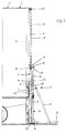
- the drawing shows a truck 1 with a container 3 having its opening 4 provided with a loading lift 5.
- the loading lift 5 comprises two vertical columns 6 being situated at both sides of the opening 4 of the container 3.
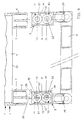
- the slider 7 is also provided with a connecting bracket 29, a hydraulic pivot cylinder 25 extending between said bracket and the loading flap 9, said cylinder 25 being provided for pivoting the loading flap 9 upwards when it is not in use and the truck must be moved.
- the hoisting mechanism 2 For moving the sliders 7 in vertical direction, the hoisting mechanism 2 is provided, which substantially consists of the basic pulling cylinder 11 and the tandem cylinder 10 with their axes being parallel.
- the upper end of the piston rod 13 is coupled to a fixed portion of the column 6, or of the truck 1, or the container 3. This can both be a pivotable and a fixed coupling.
- the upper end of the cylinder housing 14 is provided with the connecting piece 19 by which the upper end 24 of the piston rod 15 of the tandem cylinder 10 is coupled.
- the housing 12 of the tandem cylinder 12 is coupled to the mounting bracket 8 of the slider 7.
- the lower end of the housing 14 of the basic pulling cylinder 11 can be provided with support piece 27, upon which the mounting bracket 8 of the slider 7 can bear.
- a piston rod 13 For the supply and discharge of hydraulic medium to a basic pulling cylinder 11, its piston rod 13 contains a channel 21 having its upper end provided with a connection to be connected to a pressurized medium source. Through channel 21, pressurized medium can be supplied to the chamber 16, so that the housing 14 of the basic pulling cylinder 11 can be moved upwards, as seen from the position shown in Fig. 1. It will be obvious, that when said channel 21 is connected to a discharge through said connection, housing 14 will move downward as a consequence of the weight of the parts connected to it. In the same way, a channel 22 can be provided in the piston rod 15 of the tandem cylinder 10. Then, supply and discharge of pressurized medium to the chamber 17 of the tandem cylinder 10 can take place through the connecting piece 19 and a bore 18. On supply of pressurized medium to the chamber 17, the housing 12 will be moved upwards.
- the axes 26 and 28 of the basic pulling cylinder 11 and the tandem cylinder 10, respectively, are in one common vertical plane 20 being square to the plane 30 in which the columns 6 and the container opening 4 are situated.
- the axis 31 of the swivel cylinder 25 can be substantially in the same plane 30 or slightly outside of it, as appears from Fig. 4 as well.
Landscapes
- Engineering & Computer Science (AREA)
- Transportation (AREA)
- Mechanical Engineering (AREA)
- Forklifts And Lifting Vehicles (AREA)
Claims (8)
- Dispositif de hayon élévateur (5) à monter sur le conteneur (3) d'un camion (1), ledit dispositif de hayon élévateur possédant au moins deux montants (6) aptes à être montés en position verticale des deux côtés de l'ouverture (4) du conteneur, un coulisseau (7) étant monté en mobilité dans chacun desdits montants, lesdits coulisseaux (7) supportant une plate-forme de chargement (9) via un support de montage (8), au moins un des coulisseaux (7) étant relié à un mécanisme de levage (2) soit directement, soit indirectement via ledit support de montage (8), caractérisé en ce que le mécanisme de levage (8) comprend deux cylindres hydrauliques (11, 10) s'étendant en parallèle, tout en étant espacés l'un de l'autre, en direction verticale, l'extrémité supérieure de la tige de piston du premier cylindre de traction de base (11) étant couplée à une portion fixe du dispositif de hayon élévateur (5) ou du conteneur (3) et l'extrémité supérieure du logement de cylindre (14) étant munie d'une pièce de liaison (19) couplée à l'extrémité supérieure (24) d'un cylindre tandem (10) dont l'extrémité inférieure est reliée au coulisseau (7) ou au support de montage (8) concerné.
- Dispositif de hayon élévateur selon la revendication 1, caractérisé en ce que l'extrémité inférieure du logement (14) du cylindre de traction de base (11) est muni d'une pièce de support 27 sur laquelle le coulisseau (7) ou le support de montage (8) relié au coulisseau peut venir s'appuyer.
- Dispositif de hayon élévateur selon la revendication 1 ou 2, caractérisé en ce que des moyens sont prévus par lesquels le cylindre tandem (10) ne peut être actionné que lorsque le cylindre de traction de base (11) s'est complètement rétracté.
- Dispositif de hayon élévateur selon l'une quelconque des revendications précédentes, caractérisé en ce que l'extrémité du cylindre tandem (10) est couplée en pivotement à l'extrémité supérieure du logement (14) du cylindre de traction de base (11) à l'aide d'une pièce de liaison (19).
- Dispositif de hayon élévateur selon l'une quelconque des revendications précédentes, caractérisé en ce que les axes (26, 28) du cylindre de traction de base (11) et du cylindre tandem (10) qui l'accompagne, respectivement, s'étendent dans un plan vertical (20) qui est perpendiculaire au plan passant par lesdits deux montants (6) ou par l'ouverture (4) du conteneur (3).
- Dispositif de hayon élévateur selon la revendication 5, caractérisé en ce que la plate-forme de chargement (9) est reliée en pivotement au support de montage (8) et est amenée en position verticale à l'aide d'un cylindre de pivotement hydraulique (25), l'axe du cylindre de pivotement hydraulique (25) concerné étant situé dans le plan dans lequel s'étendent les axes (26, 28) du cylindre de traction de base (11) et du cylindre tandem (10).
- Dispositif de hayon élévateur selon l'une quelconque des revendications précédentes, caractérisé en ce que la tige de piston 13 du cylindre de traction de base (11) est munie d'un canal (21) s'étendant en direction longitudinale pour alimenter ou évacuer un milieu hydraulique dans le cylindre de traction de base (11) et hors de ce dernier.
- Dispositif de hayon élévateur selon la revendication 7, caractérisé en ce que la pièce de liaison (19) du cylindre de traction de base (11) est couplée à la tige de piston (15) du cylindre tandem (10) et en ce que la tige de piston (15) est munie d'un canal (22) s'étendant en direction longitudinale.
Applications Claiming Priority (4)
| Application Number | Priority Date | Filing Date | Title |
|---|---|---|---|
| BE9600289 | 1996-04-05 | ||
| BE9600289A BE1010070A6 (nl) | 1996-04-05 | 1996-04-05 | Kolomlift met dubbele hijscilinders. |
| BE9600800 | 1996-09-23 | ||
| BE9600800A BE1010643A7 (nl) | 1996-09-23 | 1996-09-23 | Kolomlift met dubbele hijscilinders. |
Publications (2)
| Publication Number | Publication Date |
|---|---|
| EP0805067A1 EP0805067A1 (fr) | 1997-11-05 |
| EP0805067B1 true EP0805067B1 (fr) | 2001-07-25 |
Family
ID=25663037
Family Applications (1)
| Application Number | Title | Priority Date | Filing Date |
|---|---|---|---|
| EP19970200956 Expired - Lifetime EP0805067B1 (fr) | 1996-04-05 | 1997-04-04 | Dispositif de hayon élévateur pour le conteneur d'un camion |
Country Status (2)
| Country | Link |
|---|---|
| EP (1) | EP0805067B1 (fr) |
| DE (1) | DE69705766T2 (fr) |
Families Citing this family (8)
| Publication number | Priority date | Publication date | Assignee | Title |
|---|---|---|---|---|
| IT1314721B1 (it) * | 2000-04-05 | 2003-01-03 | Carrozzeria Pezzaioli S R L | Pedana di carico e scarico applicabile al cassone di un veicolo ditrasporto industriale. |
| EP1380457A3 (fr) * | 2002-07-10 | 2004-04-07 | Westfalia WST Systemtechnik GmbH & Co. KG | Construction de charge pour véhicule |
| ITBS20030087A1 (it) * | 2003-09-26 | 2005-03-27 | Carrozzeria Pezzaioli S R L | Veicolo per il trasporto di bestiame. |
| ITTO20090421A1 (it) * | 2009-06-03 | 2010-12-04 | Cnh Italia Spa | Attuatore idraulico per un carrello scorrevole |
| CN102514517B (zh) * | 2011-12-15 | 2013-09-25 | 上海电机学院 | 物流汽车多级升降式尾板装置 |
| TW201339023A (zh) * | 2012-03-22 | 2013-10-01 | Sunlit Transp Company Ltd | 可升降及折收之尾門 |
| CN103358860B (zh) * | 2012-03-28 | 2015-07-08 | 山立通运股份有限公司 | 可升降及折收的尾门 |
| CN110435402A (zh) * | 2019-09-11 | 2019-11-12 | 朱从伟 | 一种车厢尾部的门中门 |
Family Cites Families (4)
| Publication number | Priority date | Publication date | Assignee | Title |
|---|---|---|---|---|
| BE613667A (fr) * | 1961-02-08 | 1962-05-29 | Burtonwood Engineering Company | Ensemble de lavage à buts multiples. |
| NL6509209A (fr) * | 1965-07-16 | 1967-01-17 | ||
| GB1413182A (en) * | 1973-05-21 | 1975-11-12 | Ratcliff Tail Lifts Ltd | Vehicle load lifting and lowering apparatus |
| BE1008664A6 (nl) * | 1994-09-02 | 1996-07-02 | Nuyts Orb | Cilinderlift. |
-
1997
- 1997-04-04 DE DE1997605766 patent/DE69705766T2/de not_active Expired - Fee Related
- 1997-04-04 EP EP19970200956 patent/EP0805067B1/fr not_active Expired - Lifetime
Also Published As
| Publication number | Publication date |
|---|---|
| DE69705766T2 (de) | 2002-05-23 |
| EP0805067A1 (fr) | 1997-11-05 |
| DE69705766D1 (de) | 2001-08-30 |
Similar Documents
| Publication | Publication Date | Title |
|---|---|---|
| CN103832310B (zh) | 车轮支撑悬置组件 | |
| US6247712B1 (en) | Trailing axle assembly | |
| CA1267105A (fr) | Elevateur pour plate-forme arriere | |
| US4147261A (en) | Loading device for goods vehicles | |
| CA1314301C (fr) | Hayon hydraulique | |
| US4522548A (en) | Aerial weapons handling trailer | |
| US4305694A (en) | Hydraulic tailgate extension, bumper and lock | |
| US5288197A (en) | Equipment trailer | |
| US3233758A (en) | Lift gate | |
| EP0805067B1 (fr) | Dispositif de hayon élévateur pour le conteneur d'un camion | |
| US4780044A (en) | Device for controlling a loading platform for transport vehicles | |
| CA1089415A (fr) | Mecanisme a cylindres pour le deploiement d'un mat sur son chariot porteur | |
| US5560063A (en) | Loading bridge for ramps | |
| US4611968A (en) | Lifting and towing apparatus for large vehicles | |
| US20050036866A1 (en) | Roll off hoist with front retractable loading frame | |
| US4382307A (en) | Transfer bridge | |
| US4993911A (en) | Mobile crane | |
| US20090115238A1 (en) | Truck Bed Lifting Device and Method | |
| SE465122B (sv) | Anordning vid lastfordon foer mottagande och avlaemning av lastenheter | |
| EP0906241B1 (fr) | Chariot enjambeur | |
| US5494309A (en) | Self-loading piggyback-type trailer unit | |
| KR102027059B1 (ko) | 화물차량에서의 적재물 앞쏠림방지 자동 작동장치 | |
| US5165707A (en) | Vertically adjustable rollbar mechanism | |
| GB2153339A (en) | Fork lift agricultural trailer | |
| CA1139271A (fr) | Appareil de levage a monter sur vehicule de transport de gros elements de charpente |
Legal Events
| Date | Code | Title | Description |
|---|---|---|---|
| PUAI | Public reference made under article 153(3) epc to a published international application that has entered the european phase |
Free format text: ORIGINAL CODE: 0009012 |
|
| AK | Designated contracting states |
Kind code of ref document: A1 Designated state(s): BE DE FR GB LU NL |
|
| 17P | Request for examination filed |
Effective date: 19980402 |
|
| 17Q | First examination report despatched |
Effective date: 19990702 |
|
| GRAG | Despatch of communication of intention to grant |
Free format text: ORIGINAL CODE: EPIDOS AGRA |
|
| GRAG | Despatch of communication of intention to grant |
Free format text: ORIGINAL CODE: EPIDOS AGRA |
|
| GRAH | Despatch of communication of intention to grant a patent |
Free format text: ORIGINAL CODE: EPIDOS IGRA |
|
| GRAH | Despatch of communication of intention to grant a patent |
Free format text: ORIGINAL CODE: EPIDOS IGRA |
|
| GRAA | (expected) grant |
Free format text: ORIGINAL CODE: 0009210 |
|
| RAP1 | Party data changed (applicant data changed or rights of an application transferred) |
Owner name: NV NUYTS ORB |
|
| AK | Designated contracting states |
Kind code of ref document: B1 Designated state(s): BE DE FR GB LU NL |
|
| RAP2 | Party data changed (patent owner data changed or rights of a patent transferred) |
Owner name: DHOLLANDIA, NAAMLOZE VENNOOTSCHAP |
|
| REF | Corresponds to: |
Ref document number: 69705766 Country of ref document: DE Date of ref document: 20010830 |
|
| NLT2 | Nl: modifications (of names), taken from the european patent patent bulletin |
Owner name: DHOLLANDIA, NAAMLOZE VENNOOTSCHAP |
|
| ET | Fr: translation filed | ||
| REG | Reference to a national code |
Ref country code: GB Ref legal event code: IF02 |
|
| PG25 | Lapsed in a contracting state [announced via postgrant information from national office to epo] |
Ref country code: LU Free format text: LAPSE BECAUSE OF NON-PAYMENT OF DUE FEES Effective date: 20020404 Ref country code: GB Free format text: LAPSE BECAUSE OF NON-PAYMENT OF DUE FEES Effective date: 20020404 |
|
| PG25 | Lapsed in a contracting state [announced via postgrant information from national office to epo] |
Ref country code: BE Free format text: LAPSE BECAUSE OF NON-PAYMENT OF DUE FEES Effective date: 20020430 |
|
| PLBE | No opposition filed within time limit |
Free format text: ORIGINAL CODE: 0009261 |
|
| STAA | Information on the status of an ep patent application or granted ep patent |
Free format text: STATUS: NO OPPOSITION FILED WITHIN TIME LIMIT |
|
| 26N | No opposition filed | ||
| PG25 | Lapsed in a contracting state [announced via postgrant information from national office to epo] |
Ref country code: NL Free format text: LAPSE BECAUSE OF NON-PAYMENT OF DUE FEES Effective date: 20021101 Ref country code: DE Free format text: LAPSE BECAUSE OF NON-PAYMENT OF DUE FEES Effective date: 20021101 |
|
| GBPC | Gb: european patent ceased through non-payment of renewal fee |
Effective date: 20020404 |
|
| PG25 | Lapsed in a contracting state [announced via postgrant information from national office to epo] |
Ref country code: FR Free format text: LAPSE BECAUSE OF NON-PAYMENT OF DUE FEES Effective date: 20021231 |
|
| NLV4 | Nl: lapsed or anulled due to non-payment of the annual fee |
Effective date: 20021101 |
|
| REG | Reference to a national code |
Ref country code: FR Ref legal event code: ST |