EP0805047B1 - Apparatus and method for recording thermal image - Google Patents
Apparatus and method for recording thermal image Download PDFInfo
- Publication number
- EP0805047B1 EP0805047B1 EP97106925A EP97106925A EP0805047B1 EP 0805047 B1 EP0805047 B1 EP 0805047B1 EP 97106925 A EP97106925 A EP 97106925A EP 97106925 A EP97106925 A EP 97106925A EP 0805047 B1 EP0805047 B1 EP 0805047B1
- Authority
- EP
- European Patent Office
- Prior art keywords
- thermal
- image
- film
- thermal head
- cleaning mode
- Prior art date
- Legal status (The legal status is an assumption and is not a legal conclusion. Google has not performed a legal analysis and makes no representation as to the accuracy of the status listed.)
- Expired - Lifetime
Links
- 238000000034 method Methods 0.000 title claims description 15
- 238000004140 cleaning Methods 0.000 claims description 50
- 239000000463 material Substances 0.000 claims description 27
- 230000003213 activating effect Effects 0.000 claims description 6
- 230000032258 transport Effects 0.000 description 22
- 230000000694 effects Effects 0.000 description 10
- 239000010410 layer Substances 0.000 description 8
- 230000001105 regulatory effect Effects 0.000 description 8
- 230000001276 controlling effect Effects 0.000 description 7
- 239000000049 pigment Substances 0.000 description 7
- 239000000126 substance Substances 0.000 description 6
- 239000002245 particle Substances 0.000 description 5
- 230000008901 benefit Effects 0.000 description 4
- 238000012423 maintenance Methods 0.000 description 4
- 230000007246 mechanism Effects 0.000 description 4
- 230000004927 fusion Effects 0.000 description 3
- 230000001681 protective effect Effects 0.000 description 3
- 238000001454 recorded image Methods 0.000 description 3
- 239000000758 substrate Substances 0.000 description 3
- PNEYBMLMFCGWSK-UHFFFAOYSA-N aluminium oxide Inorganic materials [O-2].[O-2].[O-2].[Al+3].[Al+3] PNEYBMLMFCGWSK-UHFFFAOYSA-N 0.000 description 2
- 230000005540 biological transmission Effects 0.000 description 2
- 239000000470 constituent Substances 0.000 description 2
- 238000012937 correction Methods 0.000 description 2
- 238000003745 diagnosis Methods 0.000 description 2
- 238000010438 heat treatment Methods 0.000 description 2
- 239000000314 lubricant Substances 0.000 description 2
- 229920000139 polyethylene terephthalate Polymers 0.000 description 2
- 239000005020 polyethylene terephthalate Substances 0.000 description 2
- 239000007787 solid Substances 0.000 description 2
- 239000002344 surface layer Substances 0.000 description 2
- 238000009825 accumulation Methods 0.000 description 1
- 238000003705 background correction Methods 0.000 description 1
- 239000000919 ceramic Substances 0.000 description 1
- 238000005524 ceramic coating Methods 0.000 description 1
- 238000010276 construction Methods 0.000 description 1
- 238000001816 cooling Methods 0.000 description 1
- 238000013461 design Methods 0.000 description 1
- 239000003599 detergent Substances 0.000 description 1
- 238000003702 image correction Methods 0.000 description 1
- 239000007788 liquid Substances 0.000 description 1
- 238000012986 modification Methods 0.000 description 1
- 230000004048 modification Effects 0.000 description 1
- 230000000737 periodic effect Effects 0.000 description 1
- -1 polyethylene terephthalate Polymers 0.000 description 1
- 230000008569 process Effects 0.000 description 1
- 238000012545 processing Methods 0.000 description 1
- 238000012552 review Methods 0.000 description 1
- 239000002699 waste material Substances 0.000 description 1
Images
Classifications
-
- B—PERFORMING OPERATIONS; TRANSPORTING
- B41—PRINTING; LINING MACHINES; TYPEWRITERS; STAMPS
- B41J—TYPEWRITERS; SELECTIVE PRINTING MECHANISMS, i.e. MECHANISMS PRINTING OTHERWISE THAN FROM A FORME; CORRECTION OF TYPOGRAPHICAL ERRORS
- B41J29/00—Details of, or accessories for, typewriters or selective printing mechanisms not otherwise provided for
- B41J29/17—Cleaning arrangements
-
- B—PERFORMING OPERATIONS; TRANSPORTING
- B41—PRINTING; LINING MACHINES; TYPEWRITERS; STAMPS
- B41J—TYPEWRITERS; SELECTIVE PRINTING MECHANISMS, i.e. MECHANISMS PRINTING OTHERWISE THAN FROM A FORME; CORRECTION OF TYPOGRAPHICAL ERRORS
- B41J2/00—Typewriters or selective printing mechanisms characterised by the printing or marking process for which they are designed
- B41J2/005—Typewriters or selective printing mechanisms characterised by the printing or marking process for which they are designed characterised by bringing liquid or particles selectively into contact with a printing material
- B41J2/01—Ink jet
- B41J2/135—Nozzles
- B41J2/165—Prevention or detection of nozzle clogging, e.g. cleaning, capping or moistening for nozzles
- B41J2/16517—Cleaning of print head nozzles
Definitions
- This invention relates to a thermal image recording apparatus (hereunder referred to as a "thermal recording apparatus) with which an image corresponding to image data is formed on a thermal recording material (hereunder referred to as a "thermal material”) using a thermal head.
- This invention also relates to a thermal image recording method.
- Thermal materials comprising a thermal recording layer on a paper or film substrate are commonly used to record images produced in diagnosis by ultrasonic scanning.
- This recording method commonly referred to as thermal image recording, eliminates the need for wet processing and offers several advantages including convenience in handling.
- the use of the thermal image recording system is not limited to small-scale applications such as diagnosis by ultrasonic scanning and an extension to those areas of medical diagnoses such as CT, MRI and X-ray photography where large and high-quality images are required is under review.
- the thermal recording apparatus uses the thermal head having a glaze in which heat generating elements corresponding to the number of pixels of one line are arranged in one direction and, with the glaze a little pressed against the thermal recording layer of the thermal material, the thermal material is relatively moved in a direction approximately perpendicular to the direction in which the heat generating elements are arranged, and the respective heat generating elements of the glaze are heated in accordance with the image data to be recorded to heat the thermal recording layer, thereby accomplishing image reproduction.
- the thermal material When the thermal material is pressed under the heated thermal head, the heat-sensitive substances, the lubricant and other substances in the thermal recording layer are fused on the surface to permit image reproduction. Hence, with the continued image recording, stain and the fusion products of the lubricant and other substances in the thermal recording layer tend to accumulate on the surface of the thermal head and unevenly recorded images will occur if the excessive accumulation of the fusion products gets stuck between the thermal material and the thermal head.
- the fusion products adhering to the surface of the thermal head will gradually increase in the strength of adhesion as they are kept heated with the thermal head and in some cases, they will stick so tenaciously that they cannot be easily removed by means of liquid detergent or other cleaning solutions. If the tenacious substances are difficult to remove by the cleaning operation, the only practical way to be adopted has been to scrape off the deposits from the surface of the thermal head by a suitable means such as a lapping film having a strong abrasive effect, see e.g. WO-A-93 21020.
- the lapping film has an abrasive such as alumina particles buried in the surface of a substrate film and the deposits adhering tenaciously to the surface of the thermal head can be scraped off by delivering this lapping film in place of the thermal material.
- the abrasive effect of the lapping film is so great as to remove the protective ceramic coating on the thermal head and, hence, the thermal head will wear prematurely before the end of its expected service life.
- the lapping film has the advantage of being able to remove any tenacious stain and deposits but, on the other hand, the application of the lapping film is very noisy and, hence, is not suitable in hospitals.
- the user has to perform periodic maintenance of the thermal recording apparatus, which is simply a waste of time.
- the present invention has been accomplished under these circumstances and has as an object providing a thermal image recording apparatus and method that are capable of periodically removing stains which adhered to the thermal head, without performing maintenance by means of a lapping film, and preventing stains from sticking on the thermal head.
- the invention provides a thermal image recording apparatus with which an image print corresponding to image data is produced on a thermal recording material by means of a thermal head, said apparatus having a cleaning mode in which after a specified number of image prints have been produced, said thermal head is cleaned by delivering said thermal recording material without applying energy to said thermal head or with low energy below a specified value being applied to said thermal head.
- said cleaning mode is such that no energy is applied to said thermal head, thereby allowing said thermal recording material to be delivered with no image recorded thereon.
- said cleaning mode is such that low energy below a specified value is applied to said thermal head, thereby allowing said thermal recording material to be delivered with a full-frame image being recorded at low density below a specified value.
- said cleaning mode is such that said thermal recording material is delivered with an image of a specified pattern recorded thereon, said image consisting of a blank that was produced by applying no energy to said thermal head and an area which records an image of low density below a specified value by supplying said thermal head with low energy below a specified value.
- said cleaning mode is actuated either automatically or manually.
- said apparatus further has means for switching said cleaning mode between automatically activating and manually activating.
- said apparatus has means for controlling a thermal image recording operation of said apparatus, and said controlling means controls said cleaning mode.
- controlling means controls said automatically activating on the cleaning mode.
- the invention also provides a method for thermal image recording comprising the steps of:
- thermal image recording apparatus hereunder referred to as a "thermal recording apparatus”
- thermal image recording method of the invention will now be described in detail with reference to the preferred embodiments shown in the accompanying drawings.
- Fig. 1 shows schematically an example of the thermal recording apparatus of the invention carrying out the thermal image recording method of the invention.
- the thermal image recording apparatus generally indicated by 10 in Fig. 1 performs thermal image recording on thermal recording materials of a given size, say, B4 (namely, thermal recording films A, which are hereunder referred to as "thermal films A").
- the apparatus comprises a loading section 14 where a magazine 24 containing thermal films A is loaded, a feed/transport section 16, a recording section 20 performing thermal image recording on thermal films A by means of the thermal head 66, an ejecting section 22, and means 80 for controlling the thermal image recording operation of the thermal recording apparatus 10.
- the thermal films A comprise respectively a substrate consisting of a transparent film such as a transparent polyethylene terephthalate (PET) film, which is overlaid with a thermal recording layer. Such thermal films A are stacked in a specified number, say, 100 to form a bundle. The thermal films A are accommodated in the magazine 24, and taken out of the magazine 24 one by one to be used for thermal image recording.
- a transparent film such as a transparent polyethylene terephthalate (PET) film
- the loading section 14 has an inlet 30 formed in the housing 28 of the thermal recording apparatus 10, a guide plate 32, guide rolls 34 and a stop member 36.
- the magazine 24 is inserted into the thermal recording apparatus 10 via the inlet 30 of the loading section 14 in such a way that the portion fitted with the cover 26 is coming first; thereafter, the magazine 24 as it is guided by the guide plate 32 and the guide rolls 34 is pushed until it contacts the stop member 36, whereupon it is loaded at a specified position in the thermal recording apparatus 10.
- the feed/transport section 16 has the sheet feeding mechanism using the sucker 40 for grabbing the thermal film A by application of suction, transport means 42, a transport guide 44 and a regulating roller pair 52 located in the outlet of the transport guide 44; the thermal films A are taken out of the magazine 24 in the loading section 14 and transported to the recording section 20.
- the transport means 42 is composed of a transport roller 46, a pulley 47a coaxial with the roller 46, a pulley 47b coupled to a rotating drive source, a tension pulley 47c, an endless belt 48 stretched between the three pulleys 47a, 47b and 47c, and a nip roller 50 that is to be pressed onto the transport roller 46.
- the cover 26 of the magazine 24 is opened by the OPEN/CLOSE mechanism (not shown) in the thermal recording apparatus 10. Then, the sheet feeding mechanism using the sucker 40 picks up one sheet of thermal film A from the magazine 24 and feeds the forward end of the sheet to the transport means 42 (to the nip between rollers 46 and 50).
- the sucker 40 releases the film, and the thus fed thermal film A is supplied along the transport guide 44.
- the OPEN/CLOSE mechanism closes the cover 26.
- the distance between the transport means 42 and the regulating roller pair 52 which is defined by the transport guide 44 is set to be somewhat shorter than the length of the thermal film A in the direction of its transport.
- the advancing end of the thermal film A first reaches the regulating roller pair 52 by the transport means 42.
- the regulating roller pair 52 are normally at rest. The advancing end of the thermal film A stops here.
- the temperature of the thermal head 66 is checked and if it is at a specified level, the regulating roller pair 52 start to transport the thermal film A, which is transported to the recording section.
- the recording section 20 has the thermal head 66, a platen roller 60, a fan 76 for cooling the thermal head 66, a cleaning roller pair 56, a guide 58, a guide 62, and a transport roller pair 63.
- the thermal head 66 performs thermal image recording at a recording (pixel) density of, say, 300 dpi.
- the head comprises a thermal head body having a glaze in which the heat generating elements performing one line thermal recording on the thermal film A are arranged in one direction, and a heat sink fixed to the thermal head body.
- the thermal head 66 is supported on a support member 68 that can pivot about a fulcrum 68a either in the direction of arrow a or in the reverse direction.
- the platen roller 60 rotates at a specified image recording speed while holding the thermal film A in a specified position, and transports the thermal film A in the direction approximately perpendicular to the direction in which the glaze extends.
- the cleaning roller pair 56 comprises a sticky rubber roller and a non-sticky roller.
- the support member 68 Before the thermal film A is transported to the recording section 20, the support member 68 has pivoted to UP position (in the direction opposite to the direction of arrow a ) so that the glaze of the thermal head 66 is not in contact with the platen roller 60.
- the support member 68 pivots in the direction of arrow a and the thermal film A becomes pinched between the glaze on the thermal head 66 and the platen roller 60 such that the glaze is pressed onto the recording layer while the thermal film A is transported in the direction of arrow b by means of the platen roller 60, the regulating roller pair 52 and the transport roller pair 63 as it is held in a specified position by the platen roller 60.
- the individual heat generating elements on the glaze are actuated imagewise to perform thermal image recording on the thermal film A.
- the thermal film A as it is guided by the guide 62 is transported by the platen roller 60 and the transport roller pair 63 to be ejected into a tray 72 in the ejecting section 22.
- the tray 72 projects exterior to the thermal recording apparatus 10 via the outlet 74 formed in the housing 28 and the thermal film A carrying the recorded image is ejected via the outlet 74 for takeout by the operator.
- the thermal recording apparatus of the invention operates in the above-described manner by means of the controlling means 80 during the thermal image recording (mode) and will operate in the following manner during a cleaning mode.
- the thermal recording apparatus of the invention which is generally indicated by 10 is adapted to have the "cleaning mode" in which the thermal film A is delivered as a cleaning film for the thermal head 66 after a specified number of image prints, say, 100 prints, have been produced; the delivery of the thermal film A may be accomplished in various ways such as by delivering it with no image recorded, or with an image of a predetermined density recorded, or with an image of a predetermined density and pattern recorded.
- the outermost surface of the thermal film A has pigment particles incorporated to form a protective coat on the film.
- the pigment is a solid substance that will not be fused by the heat generated from the thermal head 66 and it is incorporated in the outermost surface of the thermal film A in such a way that when the thermal film A is heated with the thermal head 66, the latter will not be blocked through adhesion to thereby ensure that a normal image can be recorded on the thermal film A in the thermal recording apparatus 10.
- the inherent function of the pigment is to ensure that the heated thermal head 66 will not be blocked by adhesion to the thermal film A to which it is being pressed.
- the polymeric film which is the support of the thermal film A is in a softened state, so the pigment which is a solid substance inherently lacks the abrasive effect of the lapping film even if it is incorporated in the outermost surface layer of the thermal film.
- the thermal film A is delivered with no energy applied to the thermal head 66(i.e., without heating it), the polymeric film which is the support of the thermal film A remains in a hardened state and the pigment, which is very hard compared to the polymeric film although not as hard as the alumina particles buried in the surface of the lapping film, will become effective as a kind of lapping film having a weak abrasive power.
- the lower the temperature of the thermal head 66 the more will the polymeric film which is the support of the thermal film A harden to thereby increase the abrasive effect of the thermal film A, enabling it to be used as a cleaning film having a less abrasive effect than the lapping film.
- the thermal film A will function as a cleaning film that relies upon the pigment particles to provide a comparatively weak abrasive effect capable of removing the surface deposit on the thermal head 66 by a thickness of less than a hundred angstroms.
- the thermal film A can be used not only as a thermal material capable of recording a desired image but also as a cleaning film having a weak abrasive effect which is variable with the temperature of the thermal head 66. Therefore, even in the case of normal image recording, the thermal head 66 will experience gradual wear of the protective ceramic coat and the wear may occasionally be as great as to form a concave 67 in a heat generating element (see Fig. 3).
- the cleaning mode shown in Fig. 2b may be selected and low energy not exceeding a specified level is applied to the thermal head 66 or it is heated to a specified low temperature or less such that the thermal film A is delivered with a full-frame image being recorded to give a specified transmission density (OD), which is 0.7 in the illustrated case.
- OD transmission density
- the polymeric support film softens to some extent and the pigment particles incorporated in the outermost surface layer of the thermal film A can penetrate deep into the concave 67 in a heat generating element on the thermal head 66, thereby achieving complete removal of any stain that has been deposited on the inner surface of the concave 67.
- the wear of the thermal head 66 usually varies from one heat generating element to another.
- the cleaning mode showing Fig. 2c may be selected, in which the energy to be applied to the thermal head 66 is varied across the center line of the thermal film A such that it is delivered with a two-step varied density pattern recorded which consists of a black area and an area recorded to a transmission density of 0.7 in the illustrated case.
- the hardness of the polymeric support film varies across the center line of the thermal film A and not only the stain deposited on the surface of a heat generating element having no concaves formed thereon but also the stain deposited on the inner surface of the concave 67 in another heat generating element can be completely removed.
- the density and pattern to be recorded on the thermal film A are determined appropriately by ensuring that the energy to be applied to the thermal head 66 is set below a specified limit at which the thermal film A will develop a sufficient abrasive effect to work as a cleaning film and the value of actual setting depends on various factors including the extent of stain of the thermal head 66, the wear of individual heat generating elements, the constituent material and thickness of the polymeric film (i.e., support of the thermal film A) and the thermal recording layer, as well as the constituent material and structural design of the thermal head 66.
- the thermal film A has a two-step varied density pattern but this is not the sole case of the present invention and the density may be varied progressively within the density range commonly used with the thermal recording apparatus 10 such as to provide a pattern having the density varied in many steps. It is preferred to deliver a thermal film A having at least two areas, one being blank and having no image recorded and the other having an image recorded to a low density below a specified level.
- the cleaning mode is actuated automatically at regular intervals and it is preferred to adapt the apparatus to have an additional capability for actuating the cleaning mode manually at any desired time.
- the thermal recording apparatus of the invention comprises switching means for switching the cleaning mode between the automatically actuating and the manually actuating. Also, it is preferred that the cleaning mode automatically actuated is controlled by the control means 80 controlling the operation of the apparatus 10.
- the thermal film A may be delivered as a cleaning film at regular intervals, say, one sheet after the delivery of 100 normal sheets and this is effective in removing the deposited stain from the thermal head 66 before it adheres tenaciously to the latter, thereby ensuring that there will be no tenacious stain deposit on the thermal head 66 in any circumstances.
- the present invention eliminates the need to perform maintenance of the thermal recording apparatus using a lapping film and due to the less abrasive effect of the cleaning film as compared with the lapping film, the thermal head can be cleaned in a reasonably quiet manner.
- Various image corrections are performed with the thermal recording apparatus and they include tone correction which intends to compensate for the difference between the image density to be produced and the density of the actually reproduced image, as well as shading correction which compensates for any unevenness in the actually reproduced image and in some of these corrections, it is necessary to output actually reproduced images of a specified density and pattern.
- tone correction intends to compensate for the difference between the image density to be produced and the density of the actually reproduced image
- shading correction which compensates for any unevenness in the actually reproduced image and in some of these corrections, it is necessary to output actually reproduced images of a specified density and pattern.
- thermal film A to be delivered as a cleaning film is not limited in any particular way and the first of the thermal films A contained in the magazine 24, or any desired film which follows it or the last film in the magazine may be delivered as a cleaning film; alternatively, a certain film may be delivered upon each magazine replacement.
- the thermal image recording apparatus and method of the invention are adapted to have a cleaning mode in which after a specified number of image prints have been produced, the thermal head is cleaned without applying energy to the head or with low energy below a specified value being applied to the head, thereby producing an image of a specified density and pattern on the thermal recording material.
- the thermal image recording apparatus and method of the invention are capable of removing stain from the thermal head before it adheres tenaciously to the head and this enables the thermal head to be kept clean throughout the operation of the recording apparatus.
- the recording apparatus of the invention periodically removes the stain deposit with the aid of a weakly abrasive thermal film so that the stain will not adhere permanently to the thermal head. This offers the advantage of eliminating the need on the part of the user to perform a special maintenance program and, further in addition, the cleaning operation performed with the apparatus and the method of the invention are less noisy than in the case of using the lapping film.
Landscapes
- Electronic Switches (AREA)
- Accessory Devices And Overall Control Thereof (AREA)
Description
- This invention relates to a thermal image recording apparatus (hereunder referred to as a "thermal recording apparatus) with which an image corresponding to image data is formed on a thermal recording material (hereunder referred to as a "thermal material") using a thermal head. This invention also relates to a thermal image recording method.
- Thermal materials comprising a thermal recording layer on a paper or film substrate are commonly used to record images produced in diagnosis by ultrasonic scanning. This recording method, commonly referred to as thermal image recording, eliminates the need for wet processing and offers several advantages including convenience in handling. Hence, the use of the thermal image recording system is not limited to small-scale applications such as diagnosis by ultrasonic scanning and an extension to those areas of medical diagnoses such as CT, MRI and X-ray photography where large and high-quality images are required is under review.
- As is well known, the thermal recording apparatus uses the thermal head having a glaze in which heat generating elements corresponding to the number of pixels of one line are arranged in one direction and, with the glaze a little pressed against the thermal recording layer of the thermal material, the thermal material is relatively moved in a direction approximately perpendicular to the direction in which the heat generating elements are arranged, and the respective heat generating elements of the glaze are heated in accordance with the image data to be recorded to heat the thermal recording layer, thereby accomplishing image reproduction.
- When the thermal material is pressed under the heated thermal head, the heat-sensitive substances, the lubricant and other substances in the thermal recording layer are fused on the surface to permit image reproduction. Hence, with the continued image recording, stain and the fusion products of the lubricant and other substances in the thermal recording layer tend to accumulate on the surface of the thermal head and unevenly recorded images will occur if the excessive accumulation of the fusion products gets stuck between the thermal material and the thermal head.
- In addition, the fusion products adhering to the surface of the thermal head will gradually increase in the strength of adhesion as they are kept heated with the thermal head and in some cases, they will stick so tenaciously that they cannot be easily removed by means of liquid detergent or other cleaning solutions. If the tenacious substances are difficult to remove by the cleaning operation, the only practical way to be adopted has been to scrape off the deposits from the surface of the thermal head by a suitable means such as a lapping film having a strong abrasive effect, see e.g. WO-A-93 21020.
- The lapping film has an abrasive such as alumina particles buried in the surface of a substrate film and the deposits adhering tenaciously to the surface of the thermal head can be scraped off by delivering this lapping film in place of the thermal material. However, the abrasive effect of the lapping film is so great as to remove the protective ceramic coating on the thermal head and, hence, the thermal head will wear prematurely before the end of its expected service life.
- The lapping film has the advantage of being able to remove any tenacious stain and deposits but, on the other hand, the application of the lapping film is very noisy and, hence, is not suitable in hospitals.
- As a further problem, the user has to perform periodic maintenance of the thermal recording apparatus, which is simply a waste of time.
- The present invention has been accomplished under these circumstances and has as an object providing a thermal image recording apparatus and method that are capable of periodically removing stains which adhered to the thermal head, without performing maintenance by means of a lapping film, and preventing stains from sticking on the thermal head.
- To achieve the above object, the invention provides a thermal image recording apparatus with which an image print corresponding to image data is produced on a thermal recording material by means of a thermal head, said apparatus having a cleaning mode in which after a specified number of image prints have been produced, said thermal head is cleaned by delivering said thermal recording material without applying energy to said thermal head or with low energy below a specified value being applied to said thermal head.
- It is preferred that said cleaning mode is such that no energy is applied to said thermal head, thereby allowing said thermal recording material to be delivered with no image recorded thereon.
- It is also preferred that said cleaning mode is such that low energy below a specified value is applied to said thermal head, thereby allowing said thermal recording material to be delivered with a full-frame image being recorded at low density below a specified value.
- It is also preferred that said cleaning mode is such that said thermal recording material is delivered with an image of a specified pattern recorded thereon, said image consisting of a blank that was produced by applying no energy to said thermal head and an area which records an image of low density below a specified value by supplying said thermal head with low energy below a specified value.
- It is further preferred that said cleaning mode is actuated either automatically or manually.
- It is also further preferred that said apparatus further has means for switching said cleaning mode between automatically activating and manually activating.
- It is still further preferred that said apparatus has means for controlling a thermal image recording operation of said apparatus, and said controlling means controls said cleaning mode.
- It is also further preferred that said controlling means controls said automatically activating on the cleaning mode.
- The invention also provides a method for thermal image recording comprising the steps of:
- producing an image corresponding to image data on a thermal recording material by means of a thermal head; and
- actuating a cleaning mode in which said thermal head is cleaned by delivering said thermal recording material without applying energy to said thermal head or with low energy below a specified value being applied to said thermal head, after a specified number of image prints have been produced.
-
-
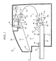
- Fig. 1 shows conceptually an example of the thermal image recording apparatus of the invention carrying out the thermal image recording method of the invention;
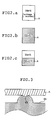
- Figs. 2a, 2b and 2c show conceptually three examples of a cleaning film which is delivered in a "cleaning mode"; and
- Fig. 3 shows conceptually a typical case of a worn heat generating element in a thermal head.
-
- The thermal image recording apparatus (hereunder referred to as a "thermal recording apparatus") and the thermal image recording method of the invention will now be described in detail with reference to the preferred embodiments shown in the accompanying drawings.
- Fig. 1 shows schematically an example of the thermal recording apparatus of the invention carrying out the thermal image recording method of the invention. The thermal image recording apparatus generally indicated by 10 in Fig. 1 performs thermal image recording on thermal recording materials of a given size, say, B4 (namely, thermal recording films A, which are hereunder referred to as "thermal films A"). The apparatus comprises a
loading section 14 where amagazine 24 containing thermal films A is loaded, a feed/transport section 16, arecording section 20 performing thermal image recording on thermal films A by means of thethermal head 66, anejecting section 22, and means 80 for controlling the thermal image recording operation of thethermal recording apparatus 10. - The thermal films A comprise respectively a substrate consisting of a transparent film such as a transparent polyethylene terephthalate (PET) film, which is overlaid with a thermal recording layer. Such thermal films A are stacked in a specified number, say, 100 to form a bundle. The thermal films A are accommodated in the
magazine 24, and taken out of themagazine 24 one by one to be used for thermal image recording. - The
loading section 14 has aninlet 30 formed in thehousing 28 of thethermal recording apparatus 10, aguide plate 32,guide rolls 34 and astop member 36. - The
magazine 24 is inserted into thethermal recording apparatus 10 via theinlet 30 of theloading section 14 in such a way that the portion fitted with thecover 26 is coming first; thereafter, themagazine 24 as it is guided by theguide plate 32 and theguide rolls 34 is pushed until it contacts thestop member 36, whereupon it is loaded at a specified position in thethermal recording apparatus 10. - The feed/
transport section 16 has the sheet feeding mechanism using thesucker 40 for grabbing the thermal film A by application of suction, transport means 42, atransport guide 44 and aregulating roller pair 52 located in the outlet of thetransport guide 44; the thermal films A are taken out of themagazine 24 in theloading section 14 and transported to therecording section 20. - The transport means 42 is composed of a transport roller 46, a
pulley 47a coaxial with the roller 46, apulley 47b coupled to a rotating drive source, atension pulley 47c, anendless belt 48 stretched between the threepulleys nip roller 50 that is to be pressed onto the transport roller 46. - When a signal for the start of recording is issued, the
cover 26 of themagazine 24 is opened by the OPEN/CLOSE mechanism (not shown) in thethermal recording apparatus 10. Then, the sheet feeding mechanism using thesucker 40 picks up one sheet of thermal film A from themagazine 24 and feeds the forward end of the sheet to the transport means 42 (to the nip between rollers 46 and 50). - At the point of time when the thermal film A has been pinched between the transport roller 46 and the
nip roller 50, thesucker 40 releases the film, and the thus fed thermal film A is supplied along thetransport guide 44. - At the point of time when the thermal film A to be used in recording has been completely ejected from the
magazine 24, the OPEN/CLOSE mechanism closes thecover 26. The distance between the transport means 42 and the regulatingroller pair 52 which is defined by thetransport guide 44 is set to be somewhat shorter than the length of the thermal film A in the direction of its transport. The advancing end of the thermal film A first reaches the regulatingroller pair 52 by the transport means 42. The regulatingroller pair 52 are normally at rest. The advancing end of the thermal film A stops here. - When the advancing end of the thermal film A reaches the regulating
roller pair 52, the temperature of thethermal head 66 is checked and if it is at a specified level, the regulatingroller pair 52 start to transport the thermal film A, which is transported to the recording section. - The
recording section 20 has thethermal head 66, aplaten roller 60, afan 76 for cooling thethermal head 66, acleaning roller pair 56, aguide 58, aguide 62, and atransport roller pair 63. - As shown, the
thermal head 66 performs thermal image recording at a recording (pixel) density of, say, 300 dpi. The head comprises a thermal head body having a glaze in which the heat generating elements performing one line thermal recording on the thermal film A are arranged in one direction, and a heat sink fixed to the thermal head body. Thethermal head 66 is supported on asupport member 68 that can pivot about afulcrum 68a either in the direction of arrow a or in the reverse direction. - The
platen roller 60 rotates at a specified image recording speed while holding the thermal film A in a specified position, and transports the thermal film A in the direction approximately perpendicular to the direction in which the glaze extends. - The
cleaning roller pair 56 comprises a sticky rubber roller and a non-sticky roller. - Before the thermal film A is transported to the
recording section 20, thesupport member 68 has pivoted to UP position (in the direction opposite to the direction of arrow a) so that the glaze of thethermal head 66 is not in contact with theplaten roller 60. - When the transport of the thermal film A by the regulating
roller pair 52 starts, said film A is subsequently pinched between thecleaning roller pair 56 and transported as it is guided by theguide 58. - When the advancing end of the thermal film A has reached the record START position (i.e., corresponding to the glaze), the
support member 68 pivots in the direction of arrow a and the thermal film A becomes pinched between the glaze on thethermal head 66 and theplaten roller 60 such that the glaze is pressed onto the recording layer while the thermal film A is transported in the direction of arrow b by means of theplaten roller 60, theregulating roller pair 52 and thetransport roller pair 63 as it is held in a specified position by theplaten roller 60. - During this transport, the individual heat generating elements on the glaze are actuated imagewise to perform thermal image recording on the thermal film A. After the end of thermal image recording, the thermal film A as it is guided by the
guide 62 is transported by theplaten roller 60 and thetransport roller pair 63 to be ejected into atray 72 in theejecting section 22. The tray 72 projects exterior to thethermal recording apparatus 10 via theoutlet 74 formed in thehousing 28 and the thermal film A carrying the recorded image is ejected via theoutlet 74 for takeout by the operator. - Having this basic construction, the thermal recording apparatus of the invention operates in the above-described manner by means of the controlling means 80 during the thermal image recording (mode) and will operate in the following manner during a cleaning mode.
- First, the operation of the apparatus during cleaning of the
thermal head 66 and the thermal image recording method of the invention will be described. - The thermal recording apparatus of the invention which is generally indicated by 10 is adapted to have the "cleaning mode" in which the thermal film A is delivered as a cleaning film for the
thermal head 66 after a specified number of image prints, say, 100 prints, have been produced; the delivery of the thermal film A may be accomplished in various ways such as by delivering it with no image recorded, or with an image of a predetermined density recorded, or with an image of a predetermined density and pattern recorded. - The outermost surface of the thermal film A has pigment particles incorporated to form a protective coat on the film. The pigment is a solid substance that will not be fused by the heat generated from the
thermal head 66 and it is incorporated in the outermost surface of the thermal film A in such a way that when the thermal film A is heated with thethermal head 66, the latter will not be blocked through adhesion to thereby ensure that a normal image can be recorded on the thermal film A in thethermal recording apparatus 10. - As just mentioned above, the inherent function of the pigment is to ensure that the heated
thermal head 66 will not be blocked by adhesion to the thermal film A to which it is being pressed. In other words, during normal image recording on the thermal film A, the polymeric film which is the support of the thermal film A is in a softened state, so the pigment which is a solid substance inherently lacks the abrasive effect of the lapping film even if it is incorporated in the outermost surface layer of the thermal film. - However, if the thermal film A is delivered with no energy applied to the thermal head 66(i.e., without heating it), the polymeric film which is the support of the thermal film A remains in a hardened state and the pigment, which is very hard compared to the polymeric film although not as hard as the alumina particles buried in the surface of the lapping film, will become effective as a kind of lapping film having a weak abrasive power.
- Therefore, the higher the temperature of the
thermal head 66, the more will the polymeric film that is the support of the thermal film A soften to thereby reduce the abrasive effect of the thermal film A. - Conversely, the lower the temperature of the
thermal head 66, the more will the polymeric film which is the support of the thermal film A harden to thereby increase the abrasive effect of the thermal film A, enabling it to be used as a cleaning film having a less abrasive effect than the lapping film. - Take, for example, the cleaning mode shown in Fig. 2a, where the thermal film A has been delivered without heating the
thermal head 66 at all, namely, with no image recorded; since the polymeric support film is in the most hardened state, the thermal film A will function as a cleaning film that relies upon the pigment particles to provide a comparatively weak abrasive effect capable of removing the surface deposit on thethermal head 66 by a thickness of less than a hundred angstroms. - Thus, the thermal film A can be used not only as a thermal material capable of recording a desired image but also as a cleaning film having a weak abrasive effect which is variable with the temperature of the
thermal head 66. Therefore, even in the case of normal image recording, thethermal head 66 will experience gradual wear of the protective ceramic coat and the wear may occasionally be as great as to form a concave 67 in a heat generating element (see Fig. 3). - In a case like this, the cleaning mode shown in Fig. 2b may be selected and low energy not exceeding a specified level is applied to the
thermal head 66 or it is heated to a specified low temperature or less such that the thermal film A is delivered with a full-frame image being recorded to give a specified transmission density (OD), which is 0.7 in the illustrated case. As a result, the polymeric support film softens to some extent and the pigment particles incorporated in the outermost surface layer of the thermal film A can penetrate deep into the concave 67 in a heat generating element on thethermal head 66, thereby achieving complete removal of any stain that has been deposited on the inner surface of the concave 67. - The wear of the
thermal head 66 usually varies from one heat generating element to another. To deal with this situation, the cleaning mode showing Fig. 2c may be selected, in which the energy to be applied to thethermal head 66 is varied across the center line of the thermal film A such that it is delivered with a two-step varied density pattern recorded which consists of a black area and an area recorded to a transmission density of 0.7 in the illustrated case. In this way, the hardness of the polymeric support film varies across the center line of the thermal film A and not only the stain deposited on the surface of a heat generating element having no concaves formed thereon but also the stain deposited on the inner surface of the concave 67 in another heat generating element can be completely removed. - In a preferred embodiment, the density and pattern to be recorded on the thermal film A are determined appropriately by ensuring that the energy to be applied to the
thermal head 66 is set below a specified limit at which the thermal film A will develop a sufficient abrasive effect to work as a cleaning film and the value of actual setting depends on various factors including the extent of stain of thethermal head 66, the wear of individual heat generating elements, the constituent material and thickness of the polymeric film (i.e., support of the thermal film A) and the thermal recording layer, as well as the constituent material and structural design of thethermal head 66. - In the case shown in Fig. 2c, the thermal film A has a two-step varied density pattern but this is not the sole case of the present invention and the density may be varied progressively within the density range commonly used with the
thermal recording apparatus 10 such as to provide a pattern having the density varied in many steps. It is preferred to deliver a thermal film A having at least two areas, one being blank and having no image recorded and the other having an image recorded to a low density below a specified level. - In a preferred embodiment, the cleaning mode is performed in the above-described manner by means of the controlling means 80.
- In the thermal recording apparatus of the invention, the cleaning mode is actuated automatically at regular intervals and it is preferred to adapt the apparatus to have an additional capability for actuating the cleaning mode manually at any desired time. In a preferred embodiment, the thermal recording apparatus of the invention comprises switching means for switching the cleaning mode between the automatically actuating and the manually actuating. Also, it is preferred that the cleaning mode automatically actuated is controlled by the control means 80 controlling the operation of the
apparatus 10. - With the thermal recording apparatus of the invention having the structural features described above, the thermal film A may be delivered as a cleaning film at regular intervals, say, one sheet after the delivery of 100 normal sheets and this is effective in removing the deposited stain from the
thermal head 66 before it adheres tenaciously to the latter, thereby ensuring that there will be no tenacious stain deposit on thethermal head 66 in any circumstances. As a further advantage, the present invention eliminates the need to perform maintenance of the thermal recording apparatus using a lapping film and due to the less abrasive effect of the cleaning film as compared with the lapping film, the thermal head can be cleaned in a reasonably quiet manner. - Various image corrections are performed with the thermal recording apparatus and they include tone correction which intends to compensate for the difference between the image density to be produced and the density of the actually reproduced image, as well as shading correction which compensates for any unevenness in the actually reproduced image and in some of these corrections, it is necessary to output actually reproduced images of a specified density and pattern. In this respect, it is preferred for the thermal recording apparatus of the invention to eliminate the wastage of the thermal film A and realize its effective use by delivering it during the cleaning mode and using it as a recorded image that is required in certain types of image correcting process.
- The foregoing example of the invention concerns the case where one sheet of cleaning film is delivered after 100 image prints have been produced; this is not the sole case of the thermal recording apparatus of the invention and it is preferred to adapt the apparatus such that it delivers one sheet of cleaning film after any specified number of image prints have been produced. It should also be noted that the thermal film A to be delivered as a cleaning film is not limited in any particular way and the first of the thermal films A contained in the
magazine 24, or any desired film which follows it or the last film in the magazine may be delivered as a cleaning film; alternatively, a certain film may be delivered upon each magazine replacement. - On the foregoing pages, the thermal image recording apparatus and method of the invention have been described in detail by reference to the specified embodiments of the thermal recording apparatus, but the present invention is in no way limited to the stated embodiments and various improvements and modifications can of course be made without departing from the scope of the claims.
- As described above in detail, the thermal image recording apparatus and method of the invention are adapted to have a cleaning mode in which after a specified number of image prints have been produced, the thermal head is cleaned without applying energy to the head or with low energy below a specified value being applied to the head, thereby producing an image of a specified density and pattern on the thermal recording material.
- Hence, the thermal image recording apparatus and method of the invention are capable of removing stain from the thermal head before it adheres tenaciously to the head and this enables the thermal head to be kept clean throughout the operation of the recording apparatus. In addition, compared with the case of removing the adhering stain by means of a highly abrasive lapping film during each maintenance operation, the recording apparatus of the invention periodically removes the stain deposit with the aid of a weakly abrasive thermal film so that the stain will not adhere permanently to the thermal head. This offers the advantage of eliminating the need on the part of the user to perform a special maintenance program and, further in addition, the cleaning operation performed with the apparatus and the method of the invention are less noisy than in the case of using the lapping film.
Claims (9)
- A thermal image recording apparatus with which an image print corresponding to image data is produced on a thermal recording material by means of a thermal head, said apparatus having a cleaning mode in which after a specified number of image prints have been produced, said thermal head is cleaned by delivering said thermal recording material without applying energy to said thermal head or with low energy below a specified value being applied to said thermal head.
- A thermal image recording apparatus according to claim 1, wherein said cleaning mode is such that no energy is applied to said thermal head, thereby allowing said thermal recording material to be delivered with no image recorded thereon.
- A thermal image recording apparatus according to claim 1, wherein said cleaning mode is such that low energy below a specified value is applied to said thermal head, thereby allowing said thermal recording material to be delivered with a full-frame image being recorded at low density below a specified value.
- A thermal image recording apparatus according to claim 1, wherein said cleaning mode is such that said thermal recording material is delivered with an image of a specified pattern recorded thereon, said image consisting of a blank that was produced by applying no energy to said thermal head and an area which records an image of low density below a specified value by supplying said thermal head with low energy below a specified value.
- A thermal image recording apparatus according to any one of claims 1-4, wherein said cleaning mode is actuated either automatically or manually.
- A thermal image recording apparatus according to claim 5, wherein said apparatus further has means for switching said cleaning mode between automatically activating and manually activating.
- A thermal image recording apparatus according to any one of claims 1-6, wherein said apparatus has means for controlling a thermal image recording operation of said apparatus, and wherein said controlling means controls said cleaning mode.
- A thermal image recording apparatus according to claim 7, wherein said controlling means controls said automatically activating on the cleaning mode.
- A method for thermal image recording comprising the steps of:producing an image corresponding to image data on a thermal recording material by means of a thermal head; andactuating a cleaning mode in which said thermal head is cleaned by delivering said thermal recording material without applying energy to said thermal head or with low energy below a specified value being applied to said thermal head, after a specified number of image prints have been produced.
Applications Claiming Priority (3)
| Application Number | Priority Date | Filing Date | Title |
|---|---|---|---|
| JP10894496A JP3602254B2 (en) | 1996-04-30 | 1996-04-30 | Thermal image recording device |
| JP10894496 | 1996-04-30 | ||
| JP108944/96 | 1996-04-30 |
Publications (2)
| Publication Number | Publication Date |
|---|---|
| EP0805047A1 EP0805047A1 (en) | 1997-11-05 |
| EP0805047B1 true EP0805047B1 (en) | 2000-03-15 |
Family
ID=14497613
Family Applications (1)
| Application Number | Title | Priority Date | Filing Date |
|---|---|---|---|
| EP97106925A Expired - Lifetime EP0805047B1 (en) | 1996-04-30 | 1997-04-25 | Apparatus and method for recording thermal image |
Country Status (4)
| Country | Link |
|---|---|
| US (1) | US5995126A (en) |
| EP (1) | EP0805047B1 (en) |
| JP (1) | JP3602254B2 (en) |
| DE (1) | DE69701416T2 (en) |
Families Citing this family (5)
| Publication number | Priority date | Publication date | Assignee | Title |
|---|---|---|---|---|
| JP2002029080A (en) | 2000-07-13 | 2002-01-29 | Fuji Photo Film Co Ltd | Thermal printer |
| US6908240B1 (en) * | 2003-12-16 | 2005-06-21 | International Imaging Materials, Inc | Thermal printing and cleaning assembly |
| JP4668699B2 (en) * | 2005-06-28 | 2011-04-13 | ノーリツ鋼機株式会社 | Printing device |
| WO2019244333A1 (en) * | 2018-06-22 | 2019-12-26 | 三菱電機株式会社 | Thermal printer |
| US11833844B2 (en) | 2020-04-28 | 2023-12-05 | Bixolon Co., Ltd. | Device for fixing platen roller for printing apparatus and printing apparatus including the same |
Family Cites Families (12)
| Publication number | Priority date | Publication date | Assignee | Title |
|---|---|---|---|---|
| JPS63159075A (en) * | 1986-12-23 | 1988-07-01 | Sharp Corp | Cleaning method for energized transfer type recording head |
| JP2705956B2 (en) * | 1987-11-11 | 1998-01-28 | キヤノン株式会社 | Ink jet recording apparatus provided with a mechanism for transporting a sheet-shaped cleaning medium to a recording area, an ejection recovery processing method employed in the apparatus, and a cleaning sheet used in the apparatus |
| EP0316198B1 (en) * | 1987-11-11 | 1994-10-19 | Canon Kabushiki Kaisha | Ink jet recording apparatus with cleaning mode |
| JPH01242278A (en) * | 1988-03-25 | 1989-09-27 | Canon Inc | Ink sheet and thermal transfer recording apparatus |
| DE8809610U1 (en) * | 1988-07-28 | 1988-09-22 | Philips Patentverwaltung Gmbh, 2000 Hamburg | Cleaning device for driven take-off rollers |
| GB2238510A (en) * | 1989-11-09 | 1991-06-05 | Dataproducts Corp | Absorbent sheets for cleaning and absorbing ink from ink-jet printheads |
| AU8669091A (en) * | 1990-09-20 | 1992-04-15 | Joseph P. Giammanco | Article and method for cleaning printers and copiers |
| US5220355A (en) * | 1991-04-10 | 1993-06-15 | Ricoh Company, Ltd. | Resistive sheet thermal transfer printer |
| DE69225758T2 (en) * | 1991-09-13 | 1998-12-24 | Canon K.K., Tokio/Tokyo | Stack of recording sheets with cleaning sheets distributed therein and a method for maintenance of the recording apparatus |
| US5227844A (en) * | 1991-10-03 | 1993-07-13 | The Texwipe Company | Cleaning sheet and method for cleaning paper path feed roller surfaces |
| WO1993021020A1 (en) * | 1992-04-09 | 1993-10-28 | Intermec Corporation | Method and apparatus for cleaning a thermal printhead |
| JP3348123B2 (en) * | 1994-02-17 | 2002-11-20 | 富士写真フイルム株式会社 | How to clean the thermal head |
-
1996
- 1996-04-30 JP JP10894496A patent/JP3602254B2/en not_active Expired - Lifetime
-
1997
- 1997-04-25 EP EP97106925A patent/EP0805047B1/en not_active Expired - Lifetime
- 1997-04-25 DE DE69701416T patent/DE69701416T2/en not_active Expired - Lifetime
- 1997-04-29 US US08/848,659 patent/US5995126A/en not_active Expired - Lifetime
Also Published As
| Publication number | Publication date |
|---|---|
| DE69701416D1 (en) | 2000-04-20 |
| US5995126A (en) | 1999-11-30 |
| DE69701416T2 (en) | 2000-07-06 |
| EP0805047A1 (en) | 1997-11-05 |
| JP3602254B2 (en) | 2004-12-15 |
| JPH09295420A (en) | 1997-11-18 |
Similar Documents
| Publication | Publication Date | Title |
|---|---|---|
| JP3337304B2 (en) | Fixing device | |
| US7284479B2 (en) | Printer operable in duplex print mode | |
| DE60310653T2 (en) | Device for thermal activation of heat-sensitive adhesive film and printer | |
| EP0805047B1 (en) | Apparatus and method for recording thermal image | |
| JP2764067B2 (en) | Method and apparatus for removing image forming substance from image carrier | |
| JP2001121785A (en) | Cleaning apparatus and cleaning method | |
| US6392679B1 (en) | Thermal printer | |
| US5907346A (en) | Method and apparatus for thermal recording | |
| JPH06161316A (en) | Image forming device | |
| JP2005035050A (en) | Image recorder | |
| JP2004058384A (en) | Perfecting press | |
| JP2001096240A (en) | Sheet cleaning device | |
| EP1607144A2 (en) | Maintenance method of medical recording apparatus and cleaning sheet for surface cleaning roller | |
| JPH1124484A (en) | Fixing device | |
| JP3224969B2 (en) | Coating device | |
| JPH0717030A (en) | Inkjet recording device | |
| JP3310850B2 (en) | Apparatus for removing image forming substance from image carrier | |
| US6081288A (en) | Thermal recording films and method of thermal image recording using the same | |
| JPS58205180A (en) | Image forming device | |
| JPS58205177A (en) | cleaning equipment | |
| JPS60204384A (en) | Paper-treating device | |
| JPH06324602A (en) | Method and device for removing image forming substance from recording paper | |
| JPH05330104A (en) | Recording apparatus | |
| JP3866079B2 (en) | Paper transport device | |
| JP2646366B2 (en) | Document reading device |
Legal Events
| Date | Code | Title | Description |
|---|---|---|---|
| PUAI | Public reference made under article 153(3) epc to a published international application that has entered the european phase |
Free format text: ORIGINAL CODE: 0009012 |
|
| AK | Designated contracting states |
Kind code of ref document: A1 Designated state(s): DE FR IT |
|
| 17P | Request for examination filed |
Effective date: 19980416 |
|
| GRAG | Despatch of communication of intention to grant |
Free format text: ORIGINAL CODE: EPIDOS AGRA |
|
| 17Q | First examination report despatched |
Effective date: 19990430 |
|
| GRAG | Despatch of communication of intention to grant |
Free format text: ORIGINAL CODE: EPIDOS AGRA |
|
| GRAH | Despatch of communication of intention to grant a patent |
Free format text: ORIGINAL CODE: EPIDOS IGRA |
|
| GRAH | Despatch of communication of intention to grant a patent |
Free format text: ORIGINAL CODE: EPIDOS IGRA |
|
| GRAA | (expected) grant |
Free format text: ORIGINAL CODE: 0009210 |
|
| AK | Designated contracting states |
Kind code of ref document: B1 Designated state(s): DE FR IT |
|
| REF | Corresponds to: |
Ref document number: 69701416 Country of ref document: DE Date of ref document: 20000420 |
|
| ITF | It: translation for a ep patent filed | ||
| ET | Fr: translation filed | ||
| PLBE | No opposition filed within time limit |
Free format text: ORIGINAL CODE: 0009261 |
|
| STAA | Information on the status of an ep patent application or granted ep patent |
Free format text: STATUS: NO OPPOSITION FILED WITHIN TIME LIMIT |
|
| 26N | No opposition filed | ||
| REG | Reference to a national code |
Ref country code: FR Ref legal event code: TP Ref country code: FR Ref legal event code: CD |
|
| REG | Reference to a national code |
Ref country code: FR Ref legal event code: ST Effective date: 20091231 |
|
| PG25 | Lapsed in a contracting state [announced via postgrant information from national office to epo] |
Ref country code: FR Free format text: LAPSE BECAUSE OF NON-PAYMENT OF DUE FEES Effective date: 20091222 |
|
| REG | Reference to a national code |
Ref country code: FR Ref legal event code: D3 |
|
| PGRI | Patent reinstated in contracting state [announced from national office to epo] |
Ref country code: FR Effective date: 20100721 |
|
| PGFP | Annual fee paid to national office [announced via postgrant information from national office to epo] |
Ref country code: DE Payment date: 20120502 Year of fee payment: 16 |
|
| PGFP | Annual fee paid to national office [announced via postgrant information from national office to epo] |
Ref country code: FR Payment date: 20120504 Year of fee payment: 16 |
|
| PGFP | Annual fee paid to national office [announced via postgrant information from national office to epo] |
Ref country code: IT Payment date: 20120421 Year of fee payment: 16 |
|
| PG25 | Lapsed in a contracting state [announced via postgrant information from national office to epo] |
Ref country code: DE Free format text: LAPSE BECAUSE OF NON-PAYMENT OF DUE FEES Effective date: 20131101 |
|
| REG | Reference to a national code |
Ref country code: FR Ref legal event code: ST Effective date: 20131231 |
|
| REG | Reference to a national code |
Ref country code: DE Ref legal event code: R119 Ref document number: 69701416 Country of ref document: DE Effective date: 20131101 |
|
| PG25 | Lapsed in a contracting state [announced via postgrant information from national office to epo] |
Ref country code: FR Free format text: LAPSE BECAUSE OF NON-PAYMENT OF DUE FEES Effective date: 20130430 Ref country code: IT Free format text: LAPSE BECAUSE OF NON-PAYMENT OF DUE FEES Effective date: 20130425 |