EP0804871B1 - Cutting machine - Google Patents
Cutting machine Download PDFInfo
- Publication number
- EP0804871B1 EP0804871B1 EP97440041A EP97440041A EP0804871B1 EP 0804871 B1 EP0804871 B1 EP 0804871B1 EP 97440041 A EP97440041 A EP 97440041A EP 97440041 A EP97440041 A EP 97440041A EP 0804871 B1 EP0804871 B1 EP 0804871B1
- Authority
- EP
- European Patent Office
- Prior art keywords
- articulation
- longitudinal axis
- cutting machine
- machine according
- cutting mechanism
- Prior art date
- Legal status (The legal status is an assumption and is not a legal conclusion. Google has not performed a legal analysis and makes no representation as to the accuracy of the status listed.)
- Expired - Lifetime
Links
- 238000005520 cutting process Methods 0.000 title claims abstract description 85
- 230000007246 mechanism Effects 0.000 claims abstract description 55
- 230000008093 supporting effect Effects 0.000 abstract description 18
- 239000003638 chemical reducing agent Substances 0.000 abstract 1
- 230000008878 coupling Effects 0.000 description 59
- 238000010168 coupling process Methods 0.000 description 59
- 238000005859 coupling reaction Methods 0.000 description 59
- 230000033001 locomotion Effects 0.000 description 3
- 230000009471 action Effects 0.000 description 1
- 230000005540 biological transmission Effects 0.000 description 1
- 230000000694 effects Effects 0.000 description 1
- 238000002955 isolation Methods 0.000 description 1
- 230000000670 limiting effect Effects 0.000 description 1
- 238000012986 modification Methods 0.000 description 1
- 230000004224 protection Effects 0.000 description 1
- 230000002441 reversible effect Effects 0.000 description 1
- 238000006467 substitution reaction Methods 0.000 description 1
Images



Classifications
-
- A—HUMAN NECESSITIES
- A01—AGRICULTURE; FORESTRY; ANIMAL HUSBANDRY; HUNTING; TRAPPING; FISHING
- A01D—HARVESTING; MOWING
- A01D34/00—Mowers; Mowing apparatus of harvesters
- A01D34/01—Mowers; Mowing apparatus of harvesters characterised by features relating to the type of cutting apparatus
- A01D34/412—Mowers; Mowing apparatus of harvesters characterised by features relating to the type of cutting apparatus having rotating cutters
- A01D34/63—Mowers; Mowing apparatus of harvesters characterised by features relating to the type of cutting apparatus having rotating cutters having cutters rotating about a vertical axis
- A01D34/64—Mowers; Mowing apparatus of harvesters characterised by features relating to the type of cutting apparatus having rotating cutters having cutters rotating about a vertical axis mounted on a vehicle, e.g. a tractor, or drawn by an animal or a vehicle
- A01D34/66—Mowers; Mowing apparatus of harvesters characterised by features relating to the type of cutting apparatus having rotating cutters having cutters rotating about a vertical axis mounted on a vehicle, e.g. a tractor, or drawn by an animal or a vehicle with two or more cutters
- A01D34/661—Mounting means
-
- Y—GENERAL TAGGING OF NEW TECHNOLOGICAL DEVELOPMENTS; GENERAL TAGGING OF CROSS-SECTIONAL TECHNOLOGIES SPANNING OVER SEVERAL SECTIONS OF THE IPC; TECHNICAL SUBJECTS COVERED BY FORMER USPC CROSS-REFERENCE ART COLLECTIONS [XRACs] AND DIGESTS
- Y10—TECHNICAL SUBJECTS COVERED BY FORMER USPC
- Y10S—TECHNICAL SUBJECTS COVERED BY FORMER USPC CROSS-REFERENCE ART COLLECTIONS [XRACs] AND DIGESTS
- Y10S56/00—Harvesters
- Y10S56/14—Hitch
Definitions
- This cutting machine comprises a carrying beam linked on the one hand to a coupling structure by means of a first articulation and on the other hand to a cutting mechanism by means of a second articulation.
- the structure coupling is intended to be linked to a motor vehicle by means of two points lower hitch and an upper hitch point.
- Cutting machine also includes a lightening device intended to lighten, in the work, the cutting mechanism.
- This lightening device has an elastic element linked on the one hand to the coupling structure by means of a third articulation and on the other hand cutting mechanism by means of a fourth articulation.
- This cutting machine is still equipped with a locking device allowing the pivoting of the structure to be locked in the transport position coupling with respect to the supporting beam and the pivoting of the section with respect to said support beam and, in the removal position, cancel said locks.
- the locking device includes a limiter linked on the one hand to the hitching structure and on the other hand to the supporting beam of sliding way.
- the limiter is provided, at the end where it is linked to the supporting beam, with a trunnion guided in oblong holes provided on said support beam. It is still provided a hook linked on the one hand to the pin and intended on the other hand to hook, in the transport position, to a fastening member secured to the cutting mechanism.
- a stand is provided, in the removal position, to support the supporting beam and the coupling structure.
- the stand is linked to the supporting beam and is controlled, when this is desired, by means of a control device, so that when the latter is actuated, said stand is put in the removal position and the action of the device relief is canceled.
- the object of the present invention is to simplify the means making it possible to remove the cutting machine while ensuring easy coupling of the said motor vehicle cutting machine.
- Such a cutting machine is easy to deposit and to couple to a vehicle engine. It will be noted that such a cutting machine does not include any stand to be put in place for the removal of said cutting machine.
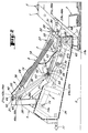
- the cutting machine (1) shown in Figures 1 to 4 is a mower (2) comprising in outline a cutting mechanism (3), a structure coupling (4), a carrying beam (5), a lightening device (6), a device locking device (7) and an operating device (8).
- the coupling structure (4) is intended to be linked to a coupling device (9) of a motor vehicle (10) by means of two lower coupling points (11, 12) and an upper coupling point (13) which are part of said structure coupling (4).
- the cutting mechanism (3) extends, seen from the rear in the direction of advance to work (15) (figure 1), to the right of the motor vehicle (10).
- the supporting beam (5) is linked on the one hand to the coupling structure (4) by means a first articulation (14) with a longitudinal axis (14a) at least substantially horizontal and directed in the direction of advance (15), and on the other hand cutting mechanism (3) by means of a second articulation (17) of axis longitudinal (17a) at least substantially parallel to said longitudinal axis (14a). In working position, the supporting beam (5) extends transversely to the direction in advance (15).
- the lightening device (6) is intended to lighten, in the working position, the cutting mechanism (3) and, in the removal position, to help maintain the hitching structure (4) in an optimal removal position allowing again easily attach the mower (2) to the motor vehicle (10).
- the lightening device (6) comprises an elastically element deformable (18) which is, according to the example shown, a tension spring (19).
- This tension spring (19) is connected at one end to an upper tie rod (20) itself linked to the coupling structure (4) by means of a third articulation (21) with a longitudinal axis (21a) at least substantially parallel to the longitudinal axis (14a) of the first articulation (14).
- the spring of traction (19) is linked to a lower tie (22) itself linked to the cutting mechanism (3) by means of a fourth articulation (23) with a longitudinal axis (23a) at least substantially parallel to the longitudinal axis (14a) of the first articulation (14).
- This operating device (8) comprises an operating element (27) and an operating member (28).
- the operating element (27) is a single-acting hydraulic cylinder (29) linked at one of its ends to the coupling structure (4) by means of a fifth articulation (30) of longitudinal axis (30a) and at the other of its ends to the operating member (28) by means of a sixth articulation (31) of longitudinal axis (31a) at least substantially parallel to said longitudinal axis (30a ).
- the operating member (28) comprises a mechanism with three levers (33) described in the French patent application 96 05051 filed on April 17, 1996 by the applicant. This operating member (28) will not be described further. For further details, reference is made, if necessary, to the text of said patent application.
- the mower (2) additionally comprises a transmission device (34) (shown schematically in dashed lines) intended to transmit the rotational movement a power take-off (not shown) from the motor vehicle (10) to the mechanism cutting (3) using a drive shaft (35) with universal joints.
- a transmission device (34) shown schematically in dashed lines
- a power take-off not shown
- the locking device (7) for its part, comprises broadly a limiter (36) and a latch (37).
- the limiter (36) is intended to limit the pivoting of the coupling structure (4) relative to the supporting beam (5) around the longitudinal axis (14a) of the first articulation (14).
- the lock (37) is intended to simultaneously lock said pivoting of the coupling structure (4) relative to the support beam (5) and the pivoting of said support beam (5) relative to the cutting mechanism (3) around the longitudinal axis (17a) of the second articulation (17).
- the limiter (36) comprises a rigid bar (39) extending in the position of work as in the removal position, from the hitching structure (4) towards the down towards the cutting mechanism (3).
- the rigid bar (39) is linked to one (40) of its ends (40, 41) at the coupling structure (4) by means of a seventh articulation (42) of axis longitudinal (42a) coincident with the longitudinal axis (21a) of the third articulation (21) and at the other (41) of its ends (40, 41) to the supporting beam (5) slidingly by means of a link (43).
- joints (21, 42) comprise, according to the example shown, a common pin (44) of longitudinal axis (44a) coincident with the longitudinal axes (21a, 42a).
- This common pin (44) extends right through through the upper tie rod (20) of the elastically deformable element (18), at through the end (40) of the rigid bar (39) and through two wings (46, 47) of the coupling structure (4), as shown in FIG. 3.
- the joints (23, 30, 31) each have a respective pin (48, 49, 50), of longitudinal axis (48a, 49a, 50a) respective, merged with the longitudinal axis (23a, 30a, 31a) corresponding to said joints (23, 30, 31).
- connection (43) also comprises a pin pin (51) longitudinal (51a) at least substantially parallel to the longitudinal axis (14a) of the first articulation (14) and two wings (53, 54) integral with the carrying beam (5).
- the ends (55, 56) of the pin (51) are each guided in a hole respective oblong (57, 58) provided in the corresponding wing (53, 54).
- Each wing (53, 54) is located in the vicinity of the middle part (60) of the beam carrier (5) so that the longitudinal axis (57a, 58a) of the oblong hole (57, 58) corresponding extends at least substantially orthogonally to the axis longitudinal (14a) of the first articulation (14) and that there remains a space between the two wings (53, 54) supporting said oblong holes (57, 58).
- the lock (37) for its part, comprises a lever (61) extending on the one hand, in removal position, substantially parallel to the support beam (5) and being linked on the other hand, at one (62) of its ends (62, 63), to the rigid bar (39) of the limiter (36) by means of an eighth articulation (64) with a longitudinal axis (64a) coincident with the longitudinal axis (51a) of the pin (51).
- the support beam (5) extends upwards.
- a second bearing surface (69) is intended to come in the position of removal, bearing on a stop (70) provided between the two wings (53, 54) of the link (43) so as to condemn the pivoting of the coupling structure (4) in the direction of the cutting mechanism (3) (i.e. in the direction of travel clockwise) around the longitudinal axis (14a) of the first articulation (14).
- the second bearing surface (69) is, according to the example shown, located on the two wings (65, 66) of the lever (61), while the stop (70) is fixed on the beam carrier (5) between the two wings (53, 54) of the link (43).
- the mower (2) rests on the ground (S) by means of the cutting mechanism (3), and the coupling structure (4) and the supporting beam (5) are in particular maintained in their removal position as shown in the Figures 2, 3 and 4 by means of the tension spring (19) and by means of the locking (7).
- the operator When the operator wishes to couple the mower (2) to the motor vehicle (10), it connects the coupling structure (4) to the coupling device (9) of the motor vehicle (10) to the by means of the two lower coupling points (11, 12) and the coupling point upper (13). To do this, it is better to first link the coupling point lower (11) lower than the coupling device (9). Then the operator lifts somewhat the latter. The pivoting around the longitudinal axes (14a, 17a) joints (14, 17) being locked, the mower (2) pivots somewhat around the end of the cutting mechanism (3) furthest from the structure coupling (4), which brings the lower coupling point (12) closer together of the coupling device (9) allowing it to be easily linked to the latter. Then, the operator links the upper coupling point (13) to the coupling device (9).
- the operator After having linked the three coupling points (11, 12, 13) of the coupling structure (4) to the coupling device (9) of the motor vehicle (10), the operator lifts further said coupling device (9) so as to pivot the mechanism section (3) down around the longitudinal axis (17a) of the second joint (17) for disengaging said cutting mechanism (3) from the first bearing surface (68) (if necessary).
- the operator retracts said lever (61) so as to release the first and the second articulation (14, 17) to authorize the pivoting of the coupling structure (4) relative to the support beam (5) around of the longitudinal axis (14a) and the pivoting of the cutting mechanism (3) by relative to said support beam (5) around the longitudinal axis (17a).
- the operator pivots the lever (61) up around the longitudinal axis (64a) from the eighth articulation (64) to a retracted position in which the longitudinal axis (61a) of said lever (61) is substantially coincident with the longitudinal axis (39a) of the rigid bar (39) of the limiter (36).
- the mower (2) being coupled to the motor vehicle (10) and, after the operator has lowered the coupling device (9) of said motor vehicle (10), it is then in the working position as shown in Figure 1.
- lever (61) occupies its retracted position in the position of work, in the swath position as well as in the transport position.
- the rigid bar (39) of the limiter (36) and / or the lever (61) of the latch (37) either (are) of adjustable length, and / or that the second bearing surface (69) of said lever (61) and / or that the stop (70) is (be) adjustable.
Landscapes
- Life Sciences & Earth Sciences (AREA)
- Environmental Sciences (AREA)
- Harvester Elements (AREA)
- Lifting Devices For Agricultural Implements (AREA)
- Confectionery (AREA)
- Control And Other Processes For Unpacking Of Materials (AREA)
- Apparatuses For Bulk Treatment Of Fruits And Vegetables And Apparatuses For Preparing Feeds (AREA)
- Road Repair (AREA)
- Working Measures On Existing Buildindgs (AREA)
- Clamps And Clips (AREA)
Abstract
Description
La présente invention concerne une machine de coupe comportant :
- un mécanisme de coupe ;
- une structure d'attelage destinée à être liée au dispositif d'attelage d'un véhicule moteur ;
- une poutre porteuse liée d'une part à la structure d'attelage au moyen d'une première articulation et d'autre part au mécanisme de coupe au moyen d'une deuxième articulation ;
- un dispositif d'allégement comportant un élément élastiquement déformable lié d'une part à la structure d'attelage au moyen d'une troisième articulation et d'autre part au mécanisme de coupe au moyen d'une quatrième articulation ;
- un dispositif de verrouillage destiné en position de transport :
- à verrouiller le pivotement de la structure d'attelage par rapport à la poutre porteuse autour de l'axe longitudinal de la première articulation ;
- à verrouiller le pivotement du mécanisme de coupe par rapport à la poutre porteuse autour de l'axe longitudinal de la deuxième articulation.
- a cutting mechanism;
- a coupling structure intended to be linked to the coupling device of a motor vehicle;
- a carrying beam linked on the one hand to the coupling structure by means of a first articulation and on the other hand to the cutting mechanism by means of a second articulation;
- a lightening device comprising an elastically deformable element linked on the one hand to the coupling structure by means of a third articulation and on the other hand to the cutting mechanism by means of a fourth articulation;
- a locking device intended for the transport position:
- locking the pivoting of the coupling structure with respect to the support beam around the longitudinal axis of the first articulation;
- locking the pivoting of the cutting mechanism relative to the support beam around the longitudinal axis of the second articulation.
Une telle machine de coupe est connue par le document FR-A-2 687 039.Such a cutting machine is known from document FR-A-2 687 039.
Cette machine de coupe comporte une poutre porteuse liée d'une part à une structure d'attelage au moyen d'une première articulation et d'autre part à un mécanisme de coupe au moyen d'une deuxième articulation. La structure d'attelage est destinée à être liée à un véhicule moteur au moyen de deux points d'attelage inférieurs et d'un point d'attelage supérieur. La machine de coupe comporte également un dispositif d'allégement destiné à alléger, en position de travail, le mécanisme de coupe.This cutting machine comprises a carrying beam linked on the one hand to a coupling structure by means of a first articulation and on the other hand to a cutting mechanism by means of a second articulation. The structure coupling is intended to be linked to a motor vehicle by means of two points lower hitch and an upper hitch point. Cutting machine also includes a lightening device intended to lighten, in the work, the cutting mechanism.
Ce dispositif d'allégement est doté d'un élément élastique lié d'une part à la structure d'attelage au moyen d'une troisième articulation et d'autre part au mécanisme de coupe au moyen d'une quatrième articulation. This lightening device has an elastic element linked on the one hand to the coupling structure by means of a third articulation and on the other hand cutting mechanism by means of a fourth articulation.
Cette machine de coupe est encore équipée d'un dispositif de verrouillage permettant de verrouiller, en position de transport, le pivotement de la structure d'attelage par rapport à la poutre porteuse et le pivotement du mécanisme de coupe par rapport à ladite poutre porteuse et, en position de dépose, d'annuler lesdits verrouillages. A cet effet, le dispositif de verrouillage comporte un limiteur lié d'une part à la structure d'attelage et d'autre part à la poutre porteuse de manière coulissante.This cutting machine is still equipped with a locking device allowing the pivoting of the structure to be locked in the transport position coupling with respect to the supporting beam and the pivoting of the section with respect to said support beam and, in the removal position, cancel said locks. To this end, the locking device includes a limiter linked on the one hand to the hitching structure and on the other hand to the supporting beam of sliding way.
Le limiteur est muni, à l'extrémité où il est lié à la poutre porteuse, d'un tourillon guidé dans des trous oblongs prévus sur ladite poutre porteuse. Il est encore prévu un crochet lié d'une part au tourillon et destiné d'autre part à s'accrocher, en position de transport, à un organe d'accrochage solidaire du mécanisme de coupe.The limiter is provided, at the end where it is linked to the supporting beam, with a trunnion guided in oblong holes provided on said support beam. It is still provided a hook linked on the one hand to the pin and intended on the other hand to hook, in the transport position, to a fastening member secured to the cutting mechanism.
Pour déposer cette machine de coupe connue, il est prévu une béquille destinée, en position de dépose, à soutenir la poutre porteuse et la structure d'attelage. A cet effet, la béquille est liée à la poutre porteuse et est commandée, lorsque cela est souhaité, au moyen d'un dispositif de commande, de sorte que, lorsque ce dernier est actionné, ladite béquille est mise en position de dépose et l'action du dispositif d'allégement est annulée.To place this known cutting machine, a stand is provided, in the removal position, to support the supporting beam and the coupling structure. In this effect, the stand is linked to the supporting beam and is controlled, when this is desired, by means of a control device, so that when the latter is actuated, said stand is put in the removal position and the action of the device relief is canceled.
Le but de la présente invention est de simplifier les moyens permettant de déposer la machine de coupe tout en garantissant un attelage aisé de ladite machine de coupe au véhicule moteur.The object of the present invention is to simplify the means making it possible to remove the cutting machine while ensuring easy coupling of the said motor vehicle cutting machine.
A cet effet, il est prévu sur la machine de coupe selon l'invention que, en position de dépose, la structure d'attelage et la poutre porteuse soient maintenues en position au moyen de l'élément élastiquement déformable du dispositif d'allégement et que le dispositif de verrouillage condamne dans au moins un sens :
- le pivotement de la structure d'attelage par rapport à la poutre porteuse autour de l'axe longitudinal de la première articulation, et
- le pivotement de la poutre porteuse par rapport au mécanisme de coupe autour de l'axe longitudinal de la deuxième articulation.
- the pivoting of the coupling structure with respect to the support beam about the longitudinal axis of the first articulation, and
- the pivoting of the support beam relative to the cutting mechanism about the longitudinal axis of the second articulation.
Une telle machine de coupe est facile à déposer et à atteler à un véhicule moteur. On remarquera qu'une telle machine de coupe ne comporte pas de béquille devant être mise en place pour la dépose de ladite machine de coupe.Such a cutting machine is easy to deposit and to couple to a vehicle engine. It will be noted that such a cutting machine does not include any stand to be put in place for the removal of said cutting machine.
L'invention concerne également les caractéristiques suivantes considérées isolément ou dans toutes leurs combinaisons techniquement possibles :
- le dispositif de verrouillage comporte un limiteur destiné à limiter le pivotement de la structure d'attelage par rapport à la poutre porteuse autour de l'axe longitudinal de la première articulation ;
- le limiteur est lié, à l'une de ses extrémités, à la structure d'attelage au moyen d'une septième articulation et, à l'autre de ses extrémités, à la poutre porteuse de manière coulissante au moyen d'une liaison comportant un tourillon d'axe longitudinal au moins sensiblement parallèle à l'axe longitudinal de la première articulation, lequel tourillon est guidé dans au moins un trou oblong implanté au moins sensiblement dans le voisinage de la partie médiane de ladite poutre porteuse ;
- il est prévu deux trous oblongs dans lesquels sont guidées les extrémités du tourillon et l'axe longitudinal de chaque trou oblong s'étend au moins sensiblement orthogonalement à l'axe longitudinal de la première articulation ;
- le dispositif de verrouillage comporte un verrou destiné à verrouiller simultanément le pivotement de la structure d'attelage par rapport à la poutre porteuse autour de l'axe longitudinal de la première articulation et le pivotement de la poutre porteuse par rapport au mécanisme de coupe autour de l'axe longitudinal de la deuxième articulation ; un tel verrou permet, d'un seul coup de main, de mettre la machine de coupe dans une position de dépose en vue de sa dépose ;
- le verrou comporte un levier lié, à l'une de ses extrémités, au limiteur au moyen d'une huitième articulation d'axe longitudinal confondu avec l'axe longitudinal du tourillon ;
- le levier comporte une première surface d'appui à son autre extrémité et une deuxième surface d'appui située entre cette première surface d'appui et la huitième articulation ;
- en position de dépose, la première surface d'appui du levier est en appui sur le mécanisme de coupe ; ce faisant, le pivotement de la poutre porteuse vers le haut, c'est-à-dire dans le sens de marche des aiguilles d'une montre, autour de l'axe longitudinal de la deuxième articulation, est condamné;
- en position de dépose, la deuxième surface d'appui du levier est en appui sur une butée prévue sur la poutre porteuse ; ce faisant, le pivotement de la structure d'attelage en direction du mécanisme de coupe, c'est-à-dire dans le sens de marche des aiguilles d'une montre, autour de l'axe longitudinal de la première articulation, est condamné ;
- ladite butée prévue sur la poutre porteuse est située entre les deux trous oblongs dans lesquels est guidé le tourillon ;
- en position de dépose, pour régler la position de la structure d'attelage, il
est prévu que :
- le limiteur soit de longueur réglable et/ou ;
- le levier soit de longueur réglable et/ou ;
- la deuxième surface d'appui soit réglable et/ou ;
- la butée soit réglable.
- dans une position autre que celle de dépose, le levier est escamoté de manière à autoriser d'une part le pivotement de la poutre porteuse par rapport à la structure d'attelage autour de l'axe longitudinal de la première articulation et d'autre part le pivotement du mécanisme de coupe par rapport à la poutre porteuse autour de l'axe longitudinal de la deuxième articulation ;
- dans une position autre que celle de dépose, le levier est escamoté de manière que son axe longitudinal soit sensiblement confondu avec l'axe longitudinal du limiteur ;
- la structure d'attelage comporte deux points d'attelage inférieurs et, en position de dépose, le point d'attelage inférieur le plus éloigné du mécanisme de coupe est situé plus bas que le point d'attelage inférieur le plus proche dudit mécanisme de coupe de manière à faciliter l'attelage de la machine de coupe au véhicule moteur.
- the locking device comprises a limiter intended to limit the pivoting of the coupling structure relative to the support beam around the longitudinal axis of the first articulation;
- the limiter is linked, at one of its ends, to the coupling structure by means of a seventh articulation and, at the other of its ends, to the carrying beam in a sliding manner by means of a connection comprising a pin of longitudinal axis at least substantially parallel to the longitudinal axis of the first articulation, which pin is guided in at least one oblong hole located at least substantially in the vicinity of the middle part of said support beam;
- two oblong holes are provided in which the ends of the trunnion are guided and the longitudinal axis of each oblong hole extends at least approximately orthogonally to the longitudinal axis of the first articulation;
- the locking device comprises a lock intended to simultaneously lock the pivoting of the coupling structure with respect to the carrying beam around the longitudinal axis of the first articulation and the pivoting of the supporting beam with respect to the cutting mechanism around the longitudinal axis of the second articulation; such a lock allows, with a single hand, to put the cutting machine in a removal position for its removal;
- the lock comprises a lever linked, at one of its ends, to the limiter by means of an eighth articulation of longitudinal axis coinciding with the longitudinal axis of the journal;
- the lever has a first bearing surface at its other end and a second bearing surface located between this first bearing surface and the eighth articulation;
- in the removal position, the first bearing surface of the lever is supported on the cutting mechanism; in doing so, the pivoting of the supporting beam upwards, that is to say in the clockwise direction of movement, around the longitudinal axis of the second articulation, is condemned;
- in the removal position, the second bearing surface of the lever is supported on a stop provided on the carrying beam; in doing so, the pivoting of the coupling structure in the direction of the cutting mechanism, that is to say in the clockwise direction of movement, around the longitudinal axis of the first articulation, is condemned ;
- said stop provided on the carrying beam is located between the two oblong holes in which the pin is guided;
- in the removal position, to adjust the position of the coupling structure, it is provided that:
- the limiter is of adjustable length and / or;
- the lever is of adjustable length and / or;
- the second bearing surface is adjustable and / or;
- the stopper is adjustable.
- in a position other than that of removal, the lever is retracted so as to allow on the one hand the pivoting of the support beam relative to the coupling structure around the longitudinal axis of the first articulation and on the other hand the pivoting of the cutting mechanism relative to the support beam about the longitudinal axis of the second articulation;
- in a position other than that of removal, the lever is retracted so that its longitudinal axis is substantially coincident with the longitudinal axis of the limiter;
- the coupling structure comprises two lower coupling points and, in the removal position, the lower coupling point furthest from the cutting mechanism is located lower than the lower coupling point closest to said cutting mechanism so as to facilitate coupling of the cutting machine to the motor vehicle.
D'autres objets, caractéristiques et avantages de l'invention apparaissent dans la description suivante avec référence aux dessins annexés qui représentent, à titre d'exemple non limitatif, une forme de réalisation de la machine de coupe selon l'invention.Other objects, characteristics and advantages of the invention appear in the following description with reference to the accompanying drawings which represent, by way of non-limiting example, an embodiment of the cutting machine according to the invention.
Sur ces dessins :
- la figure 1 représente une vue arrière d'une machine de coupe selon l'invention liée à un véhicule moteur et se trouvant dans une de ses positions de travail ;
- la figure 2 est une vue arrière de la machine de coupe de la figure 1 se trouvant dans la position de dépose ;
- la figure 3 est une vue de dessus de la machine de coupe de la figure 2 ;
- la figure 4 représente schématiquement la machine de coupe de la figure 2.
- FIG. 1 represents a rear view of a cutting machine according to the invention linked to a motor vehicle and being in one of its working positions;
- Figure 2 is a rear view of the cutting machine of Figure 1 located in the removal position;
- Figure 3 is a top view of the cutting machine of Figure 2;
- FIG. 4 schematically represents the cutting machine of FIG. 2.
La machine de coupe (1) représentée sur les figures 1 à 4 est une faucheuse (2) comportant dans les grandes lignes un mécanisme de coupe (3), une structure d'attelage (4), une poutre porteuse (5), un dispositif d'allégement (6), un dispositif de verrouillage (7) et un dispositif de manoeuvre (8).The cutting machine (1) shown in Figures 1 to 4 is a mower (2) comprising in outline a cutting mechanism (3), a structure coupling (4), a carrying beam (5), a lightening device (6), a device locking device (7) and an operating device (8).
La structure d'attelage (4) est destinée à être liée à un dispositif d'attelage (9) d'un véhicule moteur (10) au moyen de deux points d'attelage inférieurs (11, 12) et un point d'attelage supérieur (13) lesquels font partie de ladite structure d'attelage (4).The coupling structure (4) is intended to be linked to a coupling device (9) of a motor vehicle (10) by means of two lower coupling points (11, 12) and an upper coupling point (13) which are part of said structure coupling (4).
Selon l'exemple représenté, le mécanisme de coupe (3) s'étend, vue de l'arrière suivant la direction d'avance au travail (15) (figure 1), à droite du véhicule moteur (10).According to the example shown, the cutting mechanism (3) extends, seen from the rear in the direction of advance to work (15) (figure 1), to the right of the motor vehicle (10).
La poutre porteuse (5) est liée d'une part à la structure d'attelage (4) au moyen d'une première articulation (14) d'axe longitudinal (14a) au moins sensiblement horizontal et dirigé suivant la direction d'avance (15), et d'autre part au mécanisme de coupe (3) au moyen d'une deuxième articulation (17) d'axe longitudinal (17a) au moins sensiblement parallèle audit axe longitudinal (14a). En position de travail, la poutre porteuse (5) s'étend transversalement à la direction d'avance (15).The supporting beam (5) is linked on the one hand to the coupling structure (4) by means a first articulation (14) with a longitudinal axis (14a) at least substantially horizontal and directed in the direction of advance (15), and on the other hand cutting mechanism (3) by means of a second articulation (17) of axis longitudinal (17a) at least substantially parallel to said longitudinal axis (14a). In working position, the supporting beam (5) extends transversely to the direction in advance (15).
Le dispositif d'allégement (6) est destiné à alléger, en position de travail, le mécanisme de coupe (3) et, en position de dépose, à contribuer au maintien de la structure d'attelage (4) dans une position de dépose optimale permettant à nouveau d'atteler aisément la faucheuse (2) au véhicule moteur (10).The lightening device (6) is intended to lighten, in the working position, the cutting mechanism (3) and, in the removal position, to help maintain the hitching structure (4) in an optimal removal position allowing again easily attach the mower (2) to the motor vehicle (10).
A cet effet, le dispositif d'allégement (6) comporte un élément élastiquement déformable (18) qui est, selon l'exemple représenté, un ressort de traction (19). Ce ressort de traction (19) est lié à l'une de ses extrémités à un tirant supérieur (20) lui-même lié à la structure d'attelage (4) au moyen d'une troisième articulation (21) d'axe longitudinal (21a) au moins sensiblement parallèle à l'axe longitudinal (14a) de la première articulation (14). A l'autre de ses extrémités, le ressort de traction (19) est lié à un tirant inférieur (22) lui-même lié au mécanisme de coupe (3) au moyen d'une quatrième articulation (23) d'axe longitudinal (23a) au moins sensiblement parallèle à l'axe longitudinal (14a) de la première articulation (14).To this end, the lightening device (6) comprises an elastically element deformable (18) which is, according to the example shown, a tension spring (19). This tension spring (19) is connected at one end to an upper tie rod (20) itself linked to the coupling structure (4) by means of a third articulation (21) with a longitudinal axis (21a) at least substantially parallel to the longitudinal axis (14a) of the first articulation (14). At the other end, the spring of traction (19) is linked to a lower tie (22) itself linked to the cutting mechanism (3) by means of a fourth articulation (23) with a longitudinal axis (23a) at least substantially parallel to the longitudinal axis (14a) of the first articulation (14).
Le dispositif de manoeuvre (8) permet d'amener le mécanisme de coupe (3) dans :
- une position de travail où ledit mécanisme de coupe (3) s'étend d'une part sensiblement orthogonalement à la direction d'avance (15) et d'autre part sensiblement horizontalement (position de travail dite normale (figure 1)) ou vers le bas ou vers le haut (positions de travail dites particulières) ;
- une position andain où ledit mécanisme de coupe (3) s'étend au-dessus du produit coupé ou à couper ;
- une position de transport où ledit mécanisme de coupe (3) s'étend sensiblement verticalement vers le haut ; et
- une position de dépose (figures 2 à 4) dans laquelle ledit mécanisme de coupe (3) repose longitudinalement sur le sol (S).
- a working position in which said cutting mechanism (3) extends on the one hand substantially orthogonally to the direction of advance (15) and on the other hand substantially horizontally (so-called normal working position (FIG. 1)) or towards down or up (so-called specific working positions);
- a swath position where said cutting mechanism (3) extends over the cut or cut product;
- a transport position where said cutting mechanism (3) extends substantially vertically upwards; and
- a removal position (Figures 2 to 4) in which said cutting mechanism (3) rests longitudinally on the ground (S).
Ce dispositif de manoeuvre (8) comporte un élément de manoeuvre (27) et un organe de manoeuvre (28). Selon l'exemple représenté, l'élément de manoeuvre (27) est un vérin hydraulique (29) simple effet lié à l'une de ses extrémités à la structure d'attelage (4) au moyen d'une cinquième articulation (30) d'axe longitudinal (30a) et à l'autre de ses extrémités à l'organe de manoeuvre (28) au moyen d'une sixième articulation (31) d'axe longitudinal (31a) au moins sensiblement parallèle audit axe longitudinal (30a). Selon l'exemple représenté l'organe de manoeuvre (28) comporte un mécanisme à trois leviers (33) décrit dans la demande de brevet français 96 05051 déposée le 17 Avril 1996 par la demanderesse. Cet organe de manoeuvre (28) ne sera pas décrit davantage. Pour de plus amples détails, on se reportera, en cas de besoin, au texte de ladite demande de brevet.This operating device (8) comprises an operating element (27) and an operating member (28). According to the example shown, the operating element (27) is a single-acting hydraulic cylinder (29) linked at one of its ends to the coupling structure (4) by means of a fifth articulation (30) of longitudinal axis (30a) and at the other of its ends to the operating member (28) by means of a sixth articulation (31) of longitudinal axis (31a) at least substantially parallel to said longitudinal axis (30a ). According to the example shown the operating member (28) comprises a mechanism with three levers (33) described in the French patent application 96 05051 filed on April 17, 1996 by the applicant. This operating member (28) will not be described further. For further details, reference is made, if necessary, to the text of said patent application.
La faucheuse (2) comporte en sus un dispositif de transmission (34) (représenté schématiquement en traits mixtes) destiné à transmettre le mouvement de rotation d'une prise de puissance (non représentée) du véhicule moteur (10) au mécanisme de coupe (3) à l'aide d'un arbre de transmission (35) à joints universels.The mower (2) additionally comprises a transmission device (34) (shown schematically in dashed lines) intended to transmit the rotational movement a power take-off (not shown) from the motor vehicle (10) to the mechanism cutting (3) using a drive shaft (35) with universal joints.
Le dispositif de verrouillage (7) quant à lui, comporte dans les grandes lignes un limiteur (36) et un verrou (37). Le limiteur (36) est destiné à limiter le pivotement de la structure d'attelage (4) par rapport à la poutre porteuse (5) autour de l'axe longitudinal (14a) de la première articulation (14). Le verrou (37) est destiné à verrouiller simultanément ledit pivotement de la structure d'attelage (4) par rapport à la poutre porteuse (5) et le pivotement de ladite poutre porteuse (5) par rapport au mécanisme de coupe (3) autour de l'axe longitudinal (17a) de la deuxième articulation (17).The locking device (7), for its part, comprises broadly a limiter (36) and a latch (37). The limiter (36) is intended to limit the pivoting of the coupling structure (4) relative to the supporting beam (5) around the longitudinal axis (14a) of the first articulation (14). The lock (37) is intended to simultaneously lock said pivoting of the coupling structure (4) relative to the support beam (5) and the pivoting of said support beam (5) relative to the cutting mechanism (3) around the longitudinal axis (17a) of the second articulation (17).
Le limiteur (36) comporte une barre rigide (39) s'étendant, en position de travail comme en position de dépose, à partir de la structure d'attelage (4) vers le bas en direction du mécanisme de coupe (3).The limiter (36) comprises a rigid bar (39) extending in the position of work as in the removal position, from the hitching structure (4) towards the down towards the cutting mechanism (3).
A cet effet, la barre rigide (39) est liée à l'une (40) de ses extrémités (40, 41) à la structure d'attelage (4) au moyen d'une septième articulation (42) d'axe longitudinal (42a) confondu avec l'axe longitudinal (21a) de la troisième articulation (21) et à l'autre (41) de ses extrémités (40, 41) à la poutre porteuse (5) de manière coulissante au moyen d'une liaison (43). To this end, the rigid bar (39) is linked to one (40) of its ends (40, 41) at the coupling structure (4) by means of a seventh articulation (42) of axis longitudinal (42a) coincident with the longitudinal axis (21a) of the third articulation (21) and at the other (41) of its ends (40, 41) to the supporting beam (5) slidingly by means of a link (43).
On remarquera que les articulations (21, 42) comportent, selon l'exemple représenté, un tourillon commun (44) d'axe longitudinal (44a) confondu avec les axes longitudinaux (21a, 42a). Ce tourillon commun (44) s'étend de part en part au travers du tirant supérieur (20) de l'élément élastiquement déformable (18), au travers de l'extrémité (40) de la barre rigide (39) et au travers de deux ailes (46, 47) de la structure d'attelage (4), tel que représenté sur la figure 3.It will be noted that the joints (21, 42) comprise, according to the example shown, a common pin (44) of longitudinal axis (44a) coincident with the longitudinal axes (21a, 42a). This common pin (44) extends right through through the upper tie rod (20) of the elastically deformable element (18), at through the end (40) of the rigid bar (39) and through two wings (46, 47) of the coupling structure (4), as shown in FIG. 3.
On notera également que, selon l'exemple représenté, les articulations (23, 30, 31) comportent chacune un tourillon (48, 49, 50) respectif, d'axe longitudinal (48a, 49a, 50a) respectif, confondu avec l'axe longitudinal (23a, 30a, 31a) correspondant desdites articulations (23, 30, 31).It will also be noted that, according to the example shown, the joints (23, 30, 31) each have a respective pin (48, 49, 50), of longitudinal axis (48a, 49a, 50a) respective, merged with the longitudinal axis (23a, 30a, 31a) corresponding to said joints (23, 30, 31).
La liaison (43), quant à elle, comporte également un tourillon (51) d'axe longitudinal (51a) au moins sensiblement parallèle à l'axe longitudinal (14a) de la première articulation (14) et deux ailes (53, 54) solidaires de la poutre porteuse (5). Les extrémités (55, 56) du tourillon (51) sont chacune guidées dans un trou oblong (57, 58) respectif prévu dans l'aile (53, 54) correspondante. Chaque aile (53, 54) est implantée dans le voisinage de la partie médiane (60) de la poutre porteuse (5) de manière que l'axe longitudinal (57a, 58a) du trou oblong (57, 58) correspondant s'étende au moins sensiblement orthogonalement à l'axe longitudinal (14a) de la première articulation (14) et qu'il subsiste un espace entre les deux ailes (53, 54) supportant lesdits trous oblongs (57, 58).The connection (43), for its part, also comprises a pin pin (51) longitudinal (51a) at least substantially parallel to the longitudinal axis (14a) of the first articulation (14) and two wings (53, 54) integral with the carrying beam (5). The ends (55, 56) of the pin (51) are each guided in a hole respective oblong (57, 58) provided in the corresponding wing (53, 54). Each wing (53, 54) is located in the vicinity of the middle part (60) of the beam carrier (5) so that the longitudinal axis (57a, 58a) of the oblong hole (57, 58) corresponding extends at least substantially orthogonally to the axis longitudinal (14a) of the first articulation (14) and that there remains a space between the two wings (53, 54) supporting said oblong holes (57, 58).
Le verrou (37), quant à lui, comporte un levier (61) s'étendant d'une part, en position de dépose, sensiblement parallèlement à la poutre porteuse (5) et étant lié d'autre part, à l'une (62) de ses extrémités (62, 63), à la barre rigide (39) du limiteur (36) au moyen d'une huitième articulation (64) d'axe longitudinal (64a) confondu avec l'axe longitudinal (51a) du tourillon (51).The lock (37), for its part, comprises a lever (61) extending on the one hand, in removal position, substantially parallel to the support beam (5) and being linked on the other hand, at one (62) of its ends (62, 63), to the rigid bar (39) of the limiter (36) by means of an eighth articulation (64) with a longitudinal axis (64a) coincident with the longitudinal axis (51a) of the pin (51).
A cet effet, l'autre extrémité (41) de la barre rigide (39) et l'extrémité (62) du levier (61) s'étendent dans l'espace prévu entre les deux ailes (53, 54) de la liaison (43), de sorte que le tourillon (51) s'étende de part en part au travers :
- de ladite autre extrémité (41) de la barre rigide (39),
- de deux ailes (65, 66) prévues à ladite extrémité (62) dudit levier (61), et
- des trous oblongs (57, 58) desdites ailes (53, 54) tel que représenté sur la figure 3.
- from said other end (41) of the rigid bar (39),
- two wings (65, 66) provided at said end (62) of said lever (61), and
- oblong holes (57, 58) of said wings (53, 54) as shown in FIG. 3.
A l'autre extrémité (63) du levier (61) est prévue une première surface d'appui (68) venant en appui sur le mécanisme de coupe (3) en position de dépose de manière à condamner le pivotement, vers le haut, de la poutre porteuse (5) autour de l'axe longitudinal (17a) de la deuxième articulation (17).At the other end (63) of the lever (61) is provided a first bearing surface (68) bearing on the cutting mechanism (3) in the position for removing so as to lock the pivoting, upwards, of the support beam (5) around of the longitudinal axis (17a) of the second articulation (17).
En position de dépose, la poutre porteuse (5) s'étend vers le haut. Entre les deux extrémités (62, 63) du levier (61) est prévue une deuxième surface d'appui (69). Cette deuxième surface d'appui (69) est destinée à venir, en position de dépose, en appui sur une butée (70) prévue entre les deux ailes (53, 54) de la liaison (43) de manière à condamner le pivotement de la structure d'attelage (4) dans la direction du mécanisme de coupe (3) (c'est-à-dire dans le sens de marche des aiguilles d'une montre) autour de l'axe longitudinal (14a) de la première articulation (14).In the removal position, the support beam (5) extends upwards. Between the two ends (62, 63) of the lever (61) is provided a second bearing surface (69). This second bearing surface (69) is intended to come in the position of removal, bearing on a stop (70) provided between the two wings (53, 54) of the link (43) so as to condemn the pivoting of the coupling structure (4) in the direction of the cutting mechanism (3) (i.e. in the direction of travel clockwise) around the longitudinal axis (14a) of the first articulation (14).
La deuxième surface d'appui (69) est, selon l'exemple représenté, située sur les deux ailes (65, 66) du levier (61), tandis que la butée (70) est fixée sur la poutre porteuse (5) entre les deux ailes (53, 54) de la liaison (43).The second bearing surface (69) is, according to the example shown, located on the two wings (65, 66) of the lever (61), while the stop (70) is fixed on the beam carrier (5) between the two wings (53, 54) of the link (43).
A la lumière de la figure 2, on voit en sus que la barre rigide (39) du limiteur (36), le levier (61) du verrou (37), la deuxième surface d'appui (69) dudit levier (61) et la butée (70) sont agencés de manière que, en position de dépose, le point d'attelage inférieur (11) de la structure d'attelage (4) le plus éloigné du mécanisme de coupe (3) soit situé plus bas que le point d'attelage inférieur (12) le plus proche dudit mécanisme de coupe (3) afin de faciliter l'attelage de la faucheuse (2) au véhicule moteur (10).In the light of FIG. 2, it can be seen in addition that the rigid bar (39) of the limiter (36), the lever (61) of the latch (37), the second bearing surface (69) of said lever (61) and the stop (70) are arranged so that, in the removal position, the point lower coupling (11) of the coupling structure (4) furthest from the mechanism cutting (3) is located lower than the nearest lower hitch point (12) said cutting mechanism (3) in order to facilitate coupling of the mower (2) to the motor vehicle (10).
En position de dépose, la faucheuse (2) repose sur le sol (S) au moyen du mécanisme de coupe (3), et la structure d'attelage (4) et la poutre porteuse (5) sont notamment maintenues dans leur position de dépose telle que représentée sur les figures 2, 3 et 4 au moyen du ressort de traction (19) et au moyen du dispositif de verrouillage (7).In the removal position, the mower (2) rests on the ground (S) by means of the cutting mechanism (3), and the coupling structure (4) and the supporting beam (5) are in particular maintained in their removal position as shown in the Figures 2, 3 and 4 by means of the tension spring (19) and by means of the locking (7).
Lorsque l'opérateur souhaite atteler la faucheuse (2) au véhicule moteur (10), il lie la structure d'attelage (4) au dispositif d'attelage (9) du véhicule moteur (10) au moyen des deux points d'attelage inférieurs (11, 12) et du point d'attelage supérieur (13). Pour ce faire, il est préférable de lier d'abord le point d'attelage inférieur (11) le plus bas au dispositif d'attelage (9). Ensuite l'opérateur soulève quelque peu ce dernier. Les pivotements autour des axes longitudinaux (14a, 17a) des articulations (14, 17) étant condamnés, la faucheuse (2) pivote quelque peu autour de l'extrémité du mécanisme de coupe (3) la plus éloignée de la structure d'attelage (4), ce qui a pour effet de rapprocher le point d'attelage inférieur (12) du dispositif d'attelage (9) permettant de le lier aisément à ce dernier. Ensuite, l'opérateur lie le point d'attelage supérieur (13) au dispositif d'attelage (9).When the operator wishes to couple the mower (2) to the motor vehicle (10), it connects the coupling structure (4) to the coupling device (9) of the motor vehicle (10) to the by means of the two lower coupling points (11, 12) and the coupling point upper (13). To do this, it is better to first link the coupling point lower (11) lower than the coupling device (9). Then the operator lifts somewhat the latter. The pivoting around the longitudinal axes (14a, 17a) joints (14, 17) being locked, the mower (2) pivots somewhat around the end of the cutting mechanism (3) furthest from the structure coupling (4), which brings the lower coupling point (12) closer together of the coupling device (9) allowing it to be easily linked to the latter. Then, the operator links the upper coupling point (13) to the coupling device (9).
Après avoir lié les trois points d'attelage (11, 12, 13) de la structure d'attelage (4) au dispositif d'attelage (9) du véhicule moteur (10), l'opérateur soulève davantage ledit dispositif d'attelage (9) de manière à faire pivoter le mécanisme de coupe (3) vers le bas autour de l'axe longitudinal (17a) de la deuxième articulation (17) pour dégager ledit mécanisme de coupe (3) de la première surface d'appui (68) (si cela est nécessaire).After having linked the three coupling points (11, 12, 13) of the coupling structure (4) to the coupling device (9) of the motor vehicle (10), the operator lifts further said coupling device (9) so as to pivot the mechanism section (3) down around the longitudinal axis (17a) of the second joint (17) for disengaging said cutting mechanism (3) from the first bearing surface (68) (if necessary).
Une fois le levier (61) libéré, l'opérateur escamote ledit levier (61) de sorte à libérer la première et la deuxième articulation (14, 17) pour autoriser le pivotement de la structure d'attelage (4) par rapport à la poutre porteuse (5) autour de l'axe longitudinal (14a) et le pivotement du mécanisme de coupe (3) par rapport à ladite poutre porteuse (5) autour de l'axe longitudinal (17a). Pour ce faire, l'opérateur pivote le levier (61) vers le haut autour de l'axe longitudinal (64a) de la huitième articulation (64) jusque dans une position escamotée dans laquelle l'axe longitudinal (61a) dudit levier (61) soit sensiblement confondu avec l'axe longitudinal (39a) de la barre rigide (39) du limiteur (36).Once the lever (61) is released, the operator retracts said lever (61) so as to release the first and the second articulation (14, 17) to authorize the pivoting of the coupling structure (4) relative to the support beam (5) around of the longitudinal axis (14a) and the pivoting of the cutting mechanism (3) by relative to said support beam (5) around the longitudinal axis (17a). For this do, the operator pivots the lever (61) up around the longitudinal axis (64a) from the eighth articulation (64) to a retracted position in which the longitudinal axis (61a) of said lever (61) is substantially coincident with the longitudinal axis (39a) of the rigid bar (39) of the limiter (36).
La faucheuse (2) étant attelée au véhicule moteur (10) et, après que l'opérateur ait abaissé le dispositif d'attelage (9) dudit véhicule moteur (10), elle est alors dans la position de travail telle que représentée sur la figure 1.The mower (2) being coupled to the motor vehicle (10) and, after the operator has lowered the coupling device (9) of said motor vehicle (10), it is then in the working position as shown in Figure 1.
Pour mettre la faucheuse (2) de la position de travail dans la position de dépose, l'opérateur effectuera les différentes opérations en sens inverse.To put the mower (2) from the working position to the removal position, the operator will carry out the various operations in reverse.
On notera que le levier (61) occupe sa position escamotée dans la position de travail, dans la position andain ainsi que dans la position transport. It will be noted that the lever (61) occupies its retracted position in the position of work, in the swath position as well as in the transport position.
La mise en position andain et en position de transport de la faucheuse (2), ainsi que dans la position de travail à partir desdites positions andain et de transport de la faucheuse (2), s'effectue d'une manière semblable à celle décrite dans la demande de brevet français 96 05051 déposée le 17 Avril 1996. Ces différentes mises en position de la faucheuse (2) ne seront pas décrites davantage. Pour de plus amples détails, on se reportera en cas de besoin, au texte de ladite demande de brevet.The swath position and transport position of the mower (2), as well as the working position from said swath positions and transport position of the mower (2), is carried out in a manner similar to that described. in French patent application 96 05051 filed on April 17, 1996 . These different positions of the mower (2) will not be described further. For further details, reference will be made, if necessary, to the text of said patent application.
Finalement, différentes modifications restent possibles, notamment en ce qui concerne la constitution des divers éléments ou par substitution d'équivalents techniques, sans pour autant sortir du domaine de protection défini par les revendications.Finally, various modifications remain possible, in particular as regards concerns the constitution of the various elements or by substitution of equivalents technical, without departing from the scope of protection defined by the claims.
Ainsi, il est parfaitement possible de prévoir que la barre rigide (39) du limiteur (36) et/ou le levier (61) du verrou (37) soit (soient) de longueur réglable, et/ou que la deuxième surface d'appui (69) dudit levier (61) et/ou que la butée (70) soit (soient) réglable(s).Thus, it is perfectly possible to provide that the rigid bar (39) of the limiter (36) and / or the lever (61) of the latch (37) either (are) of adjustable length, and / or that the second bearing surface (69) of said lever (61) and / or that the stop (70) is (be) adjustable.
Il est également parfaitement imaginable que le mécanisme de coupe (3) de la faucheuse (2) soit agencé, vue de l'arrière suivant la direction d'avance (15), à gauche du véhicule moteur (10). Dans ce cas de figure, les différents sens de pivotement concernés décrits précédemment seraient bien entendu inversés.It is also perfectly conceivable that the cutting mechanism (3) of the mower (2) is arranged, seen from the rear in the direction of advance (15), left of the motor vehicle (10). In this case, the different meanings of pivoting concerned described above would of course be reversed.
Claims (14)
- Cutting machine including:characterized in that, in the set-down position, the hitch structure (4) and the carrying beam (5) are held in position by means of the elastically deformable element (18) of the lightening device (6) and in that the locking device (7) blocks, at least in one direction:a cutting mechanism (3);a hitch structure (4) intended to be connected to the hitch device (9) of a motor vehicle (10);a carrying beam (5) connected on the one hand to the hitch structure (4) by means of a first articulation (14) and on the other hand to the cutting mechanism (3) by means of a second articulation (17);a lightening device (6) including an elastically deformable element (18) connected on the one hand to the hitch structure (4) by means of a third articulation (21) and on the other hand to the cutting mechanism (3) by means of a fourth articulation (23);a locking device (7) intended in the transport position:to lock the pivoting of the hitch structure (4) with respect to the carrying beam (5) about the longitudinal axis (14a) of the first articulation (14),to lock the pivoting of the cutting mechanism (3) with respect to the carrying beam (5) about the longitudinal axis (17a) of the second articulation (17),the pivoting of the hitch structure (4) with respect to the carrying beam (5) about the longitudinal axis (14a) of the first articulation (14), andthe pivoting of the carrying beam (5) with respect to the cutting mechanism (3) about the longitudinal axis (17a) of the second articulation (17).
- Cutting machine according to Claim 1, characterized in that the locking device (7) includes a limiter (36) intended to limit the pivoting of the hitch structure (4) with respect to the carrying beam (5) about the longitudinal axis (14a) of the first articulation (14).
- Cutting machine according to Claim 2, characterized in that the said limiter (36) is connected, at one of its ends (40, 41), to the hitch structure (4) by means of a seventh articulation (42) and, at the other of its ends (40, 41), to the carrying beam (5) in a sliding manner by means of a connection (43) including a journal (51) of longitudinal axis (51a) at least substantially parallel to the longitudinal axis (14a) of the first articulation (14), which journal (51) is guided in at least one oblong hole (57, 58) lying at least substantially near the middle part (60) of the said carrying beam (5).
- Cutting machine according to Claim 3, characterized in that there are provided two oblong holes (57, 58) in which the ends (55, 56) of the journal (51) are guided, and in that the longitudinal axis (57a, 58a) of each oblong hole (57, 58) extends at least substantially at right angles to the longitudinal axis (14a) of the first articulation (14).
- Cutting machine according to Claim 3 or 4, characterized in that the locking device (7) includes a latch (37) intended simultaneously to lock the pivoting of the hitch structure (4) with respect to the carrying beam (5) about the longitudinal axis (14a) of the first articulation (14) and the pivoting of the carrying beam (5) with respect to the cutting mechanism (3) about the longitudinal axis (17a) of the second articulation (17).
- Cutting machine according to Claim 5, characterized in that the latch (37) includes a lever (61) connected, at one of its ends (62, 63), to the limiter (36) by means of an eighth articulation (64) of longitudinal axis (64a) coincident with the longitudinal axis (51a) of the journal (51).
- Cutting machine according to Claim 6, characterized in that the lever (61) includes a first bearing surface (68) at its other end (63) and a second bearing surface (69) situated between this first bearing surface (68) and the eighth articulation (64).
- Cutting machine according to Claim 7, characterized in that, in the set-down position, the first bearing surface (68) of the lever (61) bears on the cutting mechanism (3).
- Cutting machine according to Claim 7 or 8, characterized in that, in the set-down position, the second bearing surface (69) of the lever (61) bears against a stop (70) provided on the carrying beam (5).
- Cutting machine according to Claim 9, characterized in that the said stop (70) provided on the carrying beam (5) is situated between the two oblong holes (57, 58) in which the journal (51) is guided.
- Cutting machine according to Claim 10, characterized in that:the limiter (36) is of adjustable length and/orthe lever (61) is of adjustable length and/orthe second bearing surface (69) is adjustable and/orthe stop (70) is adjustable.
- Cutting machine according to any one of Claims 6 to 11, characterized in that, in a position other than the set-down position, the lever (61) is retracted.
- Cutting machine according to Claim 12, characterized in that, in the position other than the set-down position, the lever (61) is retracted in such a way that its longitudinal axis (61a) is substantially coincident with the longitudinal axis (39a) of the limiter (36).
- Cutting machine according to any one of Claims 1 to 11, characterized in that the hitch structure (4) includes two lower hitch points (11, 12) and in that, in the set-down position, the lower hitch point (11) furthest from the cutting mechanism (3) is situated lower down than the lower hitch point (12) closest to the said cutting mechanism (3).
Applications Claiming Priority (2)
| Application Number | Priority Date | Filing Date | Title |
|---|---|---|---|
| FR9605660 | 1996-05-02 | ||
| FR9605660A FR2748187B1 (en) | 1996-05-02 | 1996-05-02 | CUTTING MACHINE COMPRISING SIMPLIFIED MEANS FOR REMOVING IT AND ATTACHING IT TO A MOTOR VEHICLE |
Publications (2)
| Publication Number | Publication Date |
|---|---|
| EP0804871A1 EP0804871A1 (en) | 1997-11-05 |
| EP0804871B1 true EP0804871B1 (en) | 2002-02-27 |
Family
ID=9491883
Family Applications (1)
| Application Number | Title | Priority Date | Filing Date |
|---|---|---|---|
| EP97440041A Expired - Lifetime EP0804871B1 (en) | 1996-05-02 | 1997-04-28 | Cutting machine |
Country Status (9)
| Country | Link |
|---|---|
| US (1) | US5896733A (en) |
| EP (1) | EP0804871B1 (en) |
| JP (1) | JP3817624B2 (en) |
| AT (1) | ATE213587T1 (en) |
| AU (1) | AU711624B2 (en) |
| DE (1) | DE69710633T2 (en) |
| DK (1) | DK0804871T3 (en) |
| ES (1) | ES2170931T3 (en) |
| FR (1) | FR2748187B1 (en) |
Families Citing this family (8)
| Publication number | Priority date | Publication date | Assignee | Title |
|---|---|---|---|---|
| FR2794934B1 (en) | 1999-06-17 | 2001-08-10 | Kuhn Sa | AGRICULTURAL MACHINE OF THE MOWER OR MOWER CONDITIONER TYPE COMPRISING A SHOCK ABSORBER |
| WO2001006659A1 (en) * | 1999-07-16 | 2001-01-25 | Koninklijke Philips Electronics N.V. | Analog to digital conversion |
| FR2802766B1 (en) | 1999-12-23 | 2002-09-27 | Kuhn Sa | CUTTING ELEMENT OF A ROTATING PLANT CUTTING MACHINE AND ROTATING PLANT CUTTING MACHINE COMPRISING SUCH A CUTTING ELEMENT |
| FR2867350B1 (en) * | 2004-03-09 | 2006-04-28 | Kuhn Sa | CUTTING MACHINE, IN PARTICULAR AN AGRICULTURAL MOWER, WHOSE TRANSPORTATION POSITION IS SIMPLIFIED |
| FR2881021B1 (en) * | 2005-01-26 | 2007-02-23 | Kuhn Sa Sa | MOWER WITH PERFECTIONAL FOLDING AND FILLING DEVICE |
| FR2993136B1 (en) * | 2012-07-12 | 2015-04-10 | Kuhn Sa | CUTTING MACHINE HAVING AN IMPROVED DISPLACEMENT DEVICE |
| US12538867B2 (en) | 2022-08-10 | 2026-02-03 | Deere & Company | Mower with curtain assembly |
| CA3228933A1 (en) * | 2023-02-13 | 2025-04-17 | Macdon Industries Ltd | Floating cutterbar on rotary header |
Family Cites Families (18)
| Publication number | Priority date | Publication date | Assignee | Title |
|---|---|---|---|---|
| DE2630493C3 (en) * | 1976-07-07 | 1981-10-01 | Josef Bautz Gmbh, 7968 Saulgau | Rotary mower can be connected to the three-point linkage of a tractor |
| FR2458981A1 (en) * | 1979-06-19 | 1981-01-09 | Kuhn Sa | BATI OF AGRICULTURAL MACHINE |
| FR2496391A1 (en) * | 1980-12-19 | 1982-06-25 | Kuhn Sa | IMPROVEMENT TO MOWER |
| FR2502888A1 (en) * | 1981-04-02 | 1982-10-08 | Kuhn Sa | DETACHABLE LATERAL DISC PROTECTIVE CUTTER BAR |
| DE8413456U1 (en) * | 1984-05-03 | 1984-08-09 | Claas Saulgau GmbH, 7968 Saulgau | MOWING MACHINE |
| FR2598058B1 (en) * | 1986-05-02 | 1989-10-13 | Kuhn Sa | MOWER PROVIDED WITH AT LEAST ONE CUTTING MEMBER SUPPORTED BY A ROTATING DRUM |
| FR2624688B1 (en) * | 1987-12-21 | 1990-05-18 | Kuhn Sa | MOWER WITH IMPROVED CUTTING BAR RIGIDIFICATION |
| FR2626137B1 (en) * | 1988-01-22 | 1991-09-06 | Kuhn Sa | ROTARY MOWER HAVING CUTTING ORGANS EXTENDING OVER A HOUSING THROUGH GUIDANCE AND DRIVE BEARINGS |
| FR2628596B1 (en) * | 1988-03-15 | 1991-09-06 | Kuhn Sa | DIRECT DRIVE MOWER |
| FR2638056B1 (en) * | 1988-10-26 | 1991-06-07 | Kuhn Sa | MOWER WITH IMPROVED MOUNTING OF CUTTING ORGANS |
| FR2642610B1 (en) * | 1989-02-07 | 1991-05-17 | Kuhn Sa | MOWER WITH TRIGGERED SAFETY DEVICE |
| DE4110430A1 (en) * | 1991-03-29 | 1992-10-01 | Poettinger Alois Landmasch | Elevation of reaper from horizontal - using mechanism with slotted shoe fixed to carrying arm in which spigot on end of brace can slide with restricted movement |
| FR2675980B1 (en) * | 1991-04-30 | 1998-07-03 | Kuhn Sa | IMPROVED CUTTING MACHINE WITH PIVOTING HITCH STRUCTURE. |
| DE9112331U1 (en) * | 1991-10-04 | 1991-12-12 | Maschinenfabriken Bernard Krone Gmbh, 4441 Spelle | mower |
| US5203150A (en) * | 1992-01-06 | 1993-04-20 | Vermeer Manufacturing Company | Hinged shield for crop cutting apparatus |
| FR2687039B1 (en) * | 1992-02-12 | 1994-04-29 | Kuhn Sa | MOWER WITH IMPROVED LOCKING DEVICE. |
| FR2726152B1 (en) * | 1994-10-28 | 1997-01-24 | Kuhn Sa | AGRICULTURAL MACHINE FOR CUTTING PLANTS WITH IMPROVED PROTECTION DEVICE |
| FR2729817B1 (en) * | 1995-01-27 | 1997-04-11 | Kuhn Sa | CUTTING MACHINE WITH DEVICE FOR CONTROLLING THE ACTION OF A LIGHTNING SPRING OF THE CUTTING MECHANISM |
-
1996
- 1996-05-02 FR FR9605660A patent/FR2748187B1/en not_active Expired - Fee Related
-
1997
- 1997-04-25 US US08/840,929 patent/US5896733A/en not_active Expired - Lifetime
- 1997-04-28 DE DE69710633T patent/DE69710633T2/en not_active Expired - Lifetime
- 1997-04-28 AT AT97440041T patent/ATE213587T1/en active
- 1997-04-28 ES ES97440041T patent/ES2170931T3/en not_active Expired - Lifetime
- 1997-04-28 EP EP97440041A patent/EP0804871B1/en not_active Expired - Lifetime
- 1997-04-28 DK DK97440041T patent/DK0804871T3/en active
- 1997-05-01 AU AU19967/97A patent/AU711624B2/en not_active Ceased
- 1997-05-02 JP JP13042397A patent/JP3817624B2/en not_active Expired - Fee Related
Also Published As
| Publication number | Publication date |
|---|---|
| FR2748187B1 (en) | 1998-07-31 |
| EP0804871A1 (en) | 1997-11-05 |
| AU711624B2 (en) | 1999-10-21 |
| AU1996797A (en) | 1997-11-06 |
| FR2748187A1 (en) | 1997-11-07 |
| US5896733A (en) | 1999-04-27 |
| DK0804871T3 (en) | 2002-06-17 |
| ES2170931T3 (en) | 2002-08-16 |
| JPH1042649A (en) | 1998-02-17 |
| JP3817624B2 (en) | 2006-09-06 |
| DE69710633T2 (en) | 2003-02-06 |
| ATE213587T1 (en) | 2002-03-15 |
| DE69710633D1 (en) | 2002-04-04 |
Similar Documents
| Publication | Publication Date | Title |
|---|---|---|
| EP0178239B2 (en) | Method to transform a harvesting machine from a working position into a transport position, and harvesting machine using this method | |
| EP0809928B1 (en) | Cutting machine | |
| EP0356358B1 (en) | Mower with an improved frame | |
| CA2198923C (en) | Farm machinery with a linkage to a tractor and a pivoting gear housing | |
| EP0382666B1 (en) | Mower with release safety device | |
| EP0511922B1 (en) | Mowing machine with pivoting hitch structure | |
| EP0654205B1 (en) | Agricultural machine with an improved drawbar | |
| EP0552120B1 (en) | Mower with dynamic lightening device | |
| EP0709018A1 (en) | Agricultural machine used for cutting vegetables with an improved protection device | |
| FR2687039A1 (en) | MOWER WITH IMPROVED LOCKING DEVICE. | |
| EP0451074B1 (en) | Mower with improved frame | |
| EP1965630B1 (en) | Agricultural implement comprising an improved hitch structure | |
| EP0804871A1 (en) | Cutting machine | |
| EP1044593B1 (en) | Mowing machine | |
| EP0839443B1 (en) | Cutting machine | |
| EP0910940B1 (en) | Agricultural machine | |
| EP0880879B1 (en) | Agricultural machine manoeuvering device | |
| EP1843653B1 (en) | Mower provided with an improved folding and unfolding device | |
| EP2959759B1 (en) | Agricultural machine provided with a centring device | |
| EP3713390B1 (en) | Agricultural machine comprising a safety system with improved triggering kinematics | |
| EP0801887B1 (en) | Cutting machine | |
| FR2489080A1 (en) | CONNECTION DEVICE FOR ATTACHING AGRICULTURAL MACHINES TO A TRACTOR VEHICLE | |
| FR2883698A1 (en) | Tool e.g. auger, coupling device for e.g. quad bike, has rod positioning plate relative to arms for placing plate relative to arms along pivoting course of arms, or for pivoting plate relative to arms for translating plate along course |
Legal Events
| Date | Code | Title | Description |
|---|---|---|---|
| PUAI | Public reference made under article 153(3) epc to a published international application that has entered the european phase |
Free format text: ORIGINAL CODE: 0009012 |
|
| AK | Designated contracting states |
Kind code of ref document: A1 Designated state(s): AT BE DE DK ES FR GB IT NL |
|
| 17P | Request for examination filed |
Effective date: 19980422 |
|
| 17Q | First examination report despatched |
Effective date: 20000803 |
|
| GRAG | Despatch of communication of intention to grant |
Free format text: ORIGINAL CODE: EPIDOS AGRA |
|
| GRAG | Despatch of communication of intention to grant |
Free format text: ORIGINAL CODE: EPIDOS AGRA |
|
| GRAH | Despatch of communication of intention to grant a patent |
Free format text: ORIGINAL CODE: EPIDOS IGRA |
|
| GRAH | Despatch of communication of intention to grant a patent |
Free format text: ORIGINAL CODE: EPIDOS IGRA |
|
| REG | Reference to a national code |
Ref country code: GB Ref legal event code: IF02 |
|
| GRAA | (expected) grant |
Free format text: ORIGINAL CODE: 0009210 |
|
| AK | Designated contracting states |
Kind code of ref document: B1 Designated state(s): AT BE DE DK ES FR GB IT NL |
|
| REF | Corresponds to: |
Ref document number: 213587 Country of ref document: AT Date of ref document: 20020315 Kind code of ref document: T |
|
| REF | Corresponds to: |
Ref document number: 69710633 Country of ref document: DE Date of ref document: 20020404 |
|
| GBT | Gb: translation of ep patent filed (gb section 77(6)(a)/1977) |
Effective date: 20020502 |
|
| REG | Reference to a national code |
Ref country code: DK Ref legal event code: T3 |
|
| REG | Reference to a national code |
Ref country code: ES Ref legal event code: FG2A Ref document number: 2170931 Country of ref document: ES Kind code of ref document: T3 |
|
| PLBE | No opposition filed within time limit |
Free format text: ORIGINAL CODE: 0009261 |
|
| STAA | Information on the status of an ep patent application or granted ep patent |
Free format text: STATUS: NO OPPOSITION FILED WITHIN TIME LIMIT |
|
| 26N | No opposition filed |
Effective date: 20021128 |
|
| REG | Reference to a national code |
Ref country code: FR Ref legal event code: PLFP Year of fee payment: 19 |
|
| PGFP | Annual fee paid to national office [announced via postgrant information from national office to epo] |
Ref country code: DK Payment date: 20150320 Year of fee payment: 19 Ref country code: NL Payment date: 20150319 Year of fee payment: 19 |
|
| PGFP | Annual fee paid to national office [announced via postgrant information from national office to epo] |
Ref country code: GB Payment date: 20150324 Year of fee payment: 19 Ref country code: FR Payment date: 20150319 Year of fee payment: 19 |
|
| PGFP | Annual fee paid to national office [announced via postgrant information from national office to epo] |
Ref country code: BE Payment date: 20150320 Year of fee payment: 19 |
|
| PGFP | Annual fee paid to national office [announced via postgrant information from national office to epo] |
Ref country code: DE Payment date: 20150319 Year of fee payment: 19 Ref country code: ES Payment date: 20150408 Year of fee payment: 19 |
|
| PGFP | Annual fee paid to national office [announced via postgrant information from national office to epo] |
Ref country code: AT Payment date: 20150320 Year of fee payment: 19 |
|
| PG25 | Lapsed in a contracting state [announced via postgrant information from national office to epo] |
Ref country code: BE Free format text: LAPSE BECAUSE OF NON-PAYMENT OF DUE FEES Effective date: 20160430 |
|
| PGFP | Annual fee paid to national office [announced via postgrant information from national office to epo] |
Ref country code: IT Payment date: 20160324 Year of fee payment: 20 |
|
| REG | Reference to a national code |
Ref country code: DE Ref legal event code: R119 Ref document number: 69710633 Country of ref document: DE |
|
| REG | Reference to a national code |
Ref country code: DK Ref legal event code: EBP Effective date: 20160430 |
|
| REG | Reference to a national code |
Ref country code: NL Ref legal event code: MM Effective date: 20160501 |
|
| REG | Reference to a national code |
Ref country code: AT Ref legal event code: MM01 Ref document number: 213587 Country of ref document: AT Kind code of ref document: T Effective date: 20160428 |
|
| GBPC | Gb: european patent ceased through non-payment of renewal fee |
Effective date: 20160428 |
|
| REG | Reference to a national code |
Ref country code: FR Ref legal event code: ST Effective date: 20161230 |
|
| PG25 | Lapsed in a contracting state [announced via postgrant information from national office to epo] |
Ref country code: GB Free format text: LAPSE BECAUSE OF NON-PAYMENT OF DUE FEES Effective date: 20160428 Ref country code: NL Free format text: LAPSE BECAUSE OF NON-PAYMENT OF DUE FEES Effective date: 20160501 Ref country code: DE Free format text: LAPSE BECAUSE OF NON-PAYMENT OF DUE FEES Effective date: 20161101 Ref country code: FR Free format text: LAPSE BECAUSE OF NON-PAYMENT OF DUE FEES Effective date: 20160502 |
|
| PG25 | Lapsed in a contracting state [announced via postgrant information from national office to epo] |
Ref country code: AT Free format text: LAPSE BECAUSE OF NON-PAYMENT OF DUE FEES Effective date: 20160428 |
|
| PG25 | Lapsed in a contracting state [announced via postgrant information from national office to epo] |
Ref country code: DK Free format text: LAPSE BECAUSE OF NON-PAYMENT OF DUE FEES Effective date: 20160430 |
|
| REG | Reference to a national code |
Ref country code: ES Ref legal event code: FD2A Effective date: 20180507 |
|
| PG25 | Lapsed in a contracting state [announced via postgrant information from national office to epo] |
Ref country code: ES Free format text: LAPSE BECAUSE OF NON-PAYMENT OF DUE FEES Effective date: 20160429 |