EP0804812B1 - Double tape suitable for use in molten carbonate fuel cells - Google Patents
Double tape suitable for use in molten carbonate fuel cells Download PDFInfo
- Publication number
- EP0804812B1 EP0804812B1 EP95930058A EP95930058A EP0804812B1 EP 0804812 B1 EP0804812 B1 EP 0804812B1 EP 95930058 A EP95930058 A EP 95930058A EP 95930058 A EP95930058 A EP 95930058A EP 0804812 B1 EP0804812 B1 EP 0804812B1
- Authority
- EP
- European Patent Office
- Prior art keywords
- electrode
- functional layer
- current collector
- green
- tape
- Prior art date
- Legal status (The legal status is an assumption and is not a legal conclusion. Google has not performed a legal analysis and makes no representation as to the accuracy of the status listed.)
- Expired - Lifetime
Links
Images

Classifications
-
- H—ELECTRICITY
- H01—ELECTRIC ELEMENTS
- H01M—PROCESSES OR MEANS, e.g. BATTERIES, FOR THE DIRECT CONVERSION OF CHEMICAL ENERGY INTO ELECTRICAL ENERGY
- H01M8/00—Fuel cells; Manufacture thereof
- H01M8/02—Details
- H01M8/0202—Collectors; Separators, e.g. bipolar separators; Interconnectors
- H01M8/023—Porous and characterised by the material
- H01M8/0232—Metals or alloys
-
- H—ELECTRICITY
- H01—ELECTRIC ELEMENTS
- H01M—PROCESSES OR MEANS, e.g. BATTERIES, FOR THE DIRECT CONVERSION OF CHEMICAL ENERGY INTO ELECTRICAL ENERGY
- H01M8/00—Fuel cells; Manufacture thereof
- H01M8/02—Details
- H01M8/0202—Collectors; Separators, e.g. bipolar separators; Interconnectors
- H01M8/0204—Non-porous and characterised by the material
-
- H—ELECTRICITY
- H01—ELECTRIC ELEMENTS
- H01M—PROCESSES OR MEANS, e.g. BATTERIES, FOR THE DIRECT CONVERSION OF CHEMICAL ENERGY INTO ELECTRICAL ENERGY
- H01M8/00—Fuel cells; Manufacture thereof
- H01M8/02—Details
- H01M8/0202—Collectors; Separators, e.g. bipolar separators; Interconnectors
- H01M8/0247—Collectors; Separators, e.g. bipolar separators; Interconnectors characterised by the form
-
- H—ELECTRICITY
- H01—ELECTRIC ELEMENTS
- H01M—PROCESSES OR MEANS, e.g. BATTERIES, FOR THE DIRECT CONVERSION OF CHEMICAL ENERGY INTO ELECTRICAL ENERGY
- H01M8/00—Fuel cells; Manufacture thereof
- H01M8/10—Fuel cells with solid electrolytes
- H01M8/12—Fuel cells with solid electrolytes operating at high temperature, e.g. with stabilised ZrO2 electrolyte
- H01M2008/1293—Fuel cells with solid oxide electrolytes
-
- H—ELECTRICITY
- H01—ELECTRIC ELEMENTS
- H01M—PROCESSES OR MEANS, e.g. BATTERIES, FOR THE DIRECT CONVERSION OF CHEMICAL ENERGY INTO ELECTRICAL ENERGY
- H01M8/00—Fuel cells; Manufacture thereof
- H01M8/14—Fuel cells with fused electrolytes
- H01M2008/147—Fuel cells with molten carbonates
-
- H—ELECTRICITY
- H01—ELECTRIC ELEMENTS
- H01M—PROCESSES OR MEANS, e.g. BATTERIES, FOR THE DIRECT CONVERSION OF CHEMICAL ENERGY INTO ELECTRICAL ENERGY
- H01M2300/00—Electrolytes
- H01M2300/0017—Non-aqueous electrolytes
- H01M2300/0048—Molten electrolytes used at high temperature
- H01M2300/0051—Carbonates
-
- H—ELECTRICITY
- H01—ELECTRIC ELEMENTS
- H01M—PROCESSES OR MEANS, e.g. BATTERIES, FOR THE DIRECT CONVERSION OF CHEMICAL ENERGY INTO ELECTRICAL ENERGY
- H01M2300/00—Electrolytes
- H01M2300/0017—Non-aqueous electrolytes
- H01M2300/0065—Solid electrolytes
- H01M2300/0068—Solid electrolytes inorganic
- H01M2300/0071—Oxides
- H01M2300/0074—Ion conductive at high temperature
-
- Y—GENERAL TAGGING OF NEW TECHNOLOGICAL DEVELOPMENTS; GENERAL TAGGING OF CROSS-SECTIONAL TECHNOLOGIES SPANNING OVER SEVERAL SECTIONS OF THE IPC; TECHNICAL SUBJECTS COVERED BY FORMER USPC CROSS-REFERENCE ART COLLECTIONS [XRACs] AND DIGESTS
- Y02—TECHNOLOGIES OR APPLICATIONS FOR MITIGATION OR ADAPTATION AGAINST CLIMATE CHANGE
- Y02E—REDUCTION OF GREENHOUSE GAS [GHG] EMISSIONS, RELATED TO ENERGY GENERATION, TRANSMISSION OR DISTRIBUTION
- Y02E60/00—Enabling technologies; Technologies with a potential or indirect contribution to GHG emissions mitigation
- Y02E60/10—Energy storage using batteries
-
- Y—GENERAL TAGGING OF NEW TECHNOLOGICAL DEVELOPMENTS; GENERAL TAGGING OF CROSS-SECTIONAL TECHNOLOGIES SPANNING OVER SEVERAL SECTIONS OF THE IPC; TECHNICAL SUBJECTS COVERED BY FORMER USPC CROSS-REFERENCE ART COLLECTIONS [XRACs] AND DIGESTS
- Y02—TECHNOLOGIES OR APPLICATIONS FOR MITIGATION OR ADAPTATION AGAINST CLIMATE CHANGE
- Y02E—REDUCTION OF GREENHOUSE GAS [GHG] EMISSIONS, RELATED TO ENERGY GENERATION, TRANSMISSION OR DISTRIBUTION
- Y02E60/00—Enabling technologies; Technologies with a potential or indirect contribution to GHG emissions mitigation
- Y02E60/30—Hydrogen technology
- Y02E60/50—Fuel cells
-
- Y—GENERAL TAGGING OF NEW TECHNOLOGICAL DEVELOPMENTS; GENERAL TAGGING OF CROSS-SECTIONAL TECHNOLOGIES SPANNING OVER SEVERAL SECTIONS OF THE IPC; TECHNICAL SUBJECTS COVERED BY FORMER USPC CROSS-REFERENCE ART COLLECTIONS [XRACs] AND DIGESTS
- Y02—TECHNOLOGIES OR APPLICATIONS FOR MITIGATION OR ADAPTATION AGAINST CLIMATE CHANGE
- Y02P—CLIMATE CHANGE MITIGATION TECHNOLOGIES IN THE PRODUCTION OR PROCESSING OF GOODS
- Y02P70/00—Climate change mitigation technologies in the production process for final industrial or consumer products
- Y02P70/50—Manufacturing or production processes characterised by the final manufactured product
-
- Y—GENERAL TAGGING OF NEW TECHNOLOGICAL DEVELOPMENTS; GENERAL TAGGING OF CROSS-SECTIONAL TECHNOLOGIES SPANNING OVER SEVERAL SECTIONS OF THE IPC; TECHNICAL SUBJECTS COVERED BY FORMER USPC CROSS-REFERENCE ART COLLECTIONS [XRACs] AND DIGESTS
- Y10—TECHNICAL SUBJECTS COVERED BY FORMER USPC
- Y10T—TECHNICAL SUBJECTS COVERED BY FORMER US CLASSIFICATION
- Y10T29/00—Metal working
- Y10T29/49—Method of mechanical manufacture
- Y10T29/49002—Electrical device making
- Y10T29/49108—Electric battery cell making
-
- Y—GENERAL TAGGING OF NEW TECHNOLOGICAL DEVELOPMENTS; GENERAL TAGGING OF CROSS-SECTIONAL TECHNOLOGIES SPANNING OVER SEVERAL SECTIONS OF THE IPC; TECHNICAL SUBJECTS COVERED BY FORMER USPC CROSS-REFERENCE ART COLLECTIONS [XRACs] AND DIGESTS
- Y10—TECHNICAL SUBJECTS COVERED BY FORMER USPC
- Y10T—TECHNICAL SUBJECTS COVERED BY FORMER US CLASSIFICATION
- Y10T29/00—Metal working
- Y10T29/49—Method of mechanical manufacture
- Y10T29/49002—Electrical device making
- Y10T29/49108—Electric battery cell making
- Y10T29/49115—Electric battery cell making including coating or impregnating
Definitions
- the present invention relates to a method according to the preamble of Claim 1.
- nickel oxide in the electrodes in the first instance provides an effective electrochemical cell, more in particular a fuel cell, but in the long term it was found that internal short circuits arise. Consequently, the use of nickel oxide electrodes is undesirable.
- the object of the present invention is to avoid the above- described drawbacks and to provide a fuel cell with electrodes having, on the one hand, an adequate service life and, on the other hand, a low transition resistance between electrode and current collector by virtue of an effective functional layer being employed.
- This attachment operation can take place in any manner known in the prior art.
- the electrode can be fabricated by this method. Then the functional layer can be applied by spraying, screen printing and the like.
- both the functional layer and the electrode it is also, and preferably, possible to fabricate both the functional layer and the electrode by a tape casting technique and combine them immediately thereafter.
- the solvent employed for the binder of both the electrode and the functional layer preferably has the same basis.
- the separate components to be assembled consist, according to the invention, of materials of a similar type. This means that during start-up and operation only metal-metal or, for example, oxide-oxide contacts are formed and preferably no metal-oxide contacts. It is moreover important for the invention that prior to, during and after these contacts being formed, corrosion problems do not arise, particularly at the interface of the (stainless steel) current collector and the electrode. Corrosion worsens the electrical contact.
- the thin layer on the one hand, is absorbed (in part) by the current collector and, on the other hand, (in part) by the electrode, so that it can no longer be distinguished in a sharply defined manner.
- the above-described objectives are achieved, however.
- the layer being (in part) absorbed by the current collector indicates that contact formation is not adversely affected by (premature) corrosion.
- the thin, comparatively soft layer can be applied to the electrode or to the current collector (or optionally corrugation plate) in any way known in the prior art.
- the layer will preferably contain metal particles for the subsequent formation, during sintering, of a contact with the current collector.
- the layer when being applied to the current collector or corrugation plate, the layer will preferably contain electrode material or similar material (oxide) for the contact to be formed subsequently with the electrode.
- electrode material or similar material oxide
- One possible way of applying it is by means of tape casting, the same method which is used for the fabrication of electrodes.
- a corresponding alternative possibility is screen printing.
- the cell during start-up to be heated for several hours to approximately 500°C, in order to bake out the necessarily present binder and to melt the electrolyte. Then the cell can be heated to 650°C. This applies particularly to a molten-carbonate cell.
- the nickel material diffuses into the stainless steel and thus provides adhesion between current collector and electrode. Owing to the high nickel percentage, the oxidation resistance of the current collector increases. Surprisingly it was found that the nickel material does not diffuse into the adjacent electrode or cathode, respectively, so that the properties thereof are unchanged.
- the thickness of the functional layer can be between 20 ⁇ m and 150 ⁇ m.
- the thickness of the electrode is in the order of magnitude of tenths of millimetres.
- the invention also relates to an electrochemical cell comprising green components according to Claim 5.
- the metal employed in the functional layer preferably comprises a metal from the iron group.
- lithium cobaltate (LiCoO 2 ) was employed as the cathode material.
- This material has advantages with respect to a cell which is provided with the more customary nickel oxide (NiO) cathode. This relates especially to the service life. If the lithium cobaltate is moreover applied as a green tape, handling is easier and a reduction in cost is achieved, compared with a component sintered beforehand. According to the invention it is proposed to provide this green tape with a thin tape which contains metal powder, the transition resistance between the cathode/current collector being considerably reduced as a result.
- the above-described lithium cobaltate is preferably employed as a powder.
- This can be obtained in any way known in the prior art.
- the powder was obtained via a solid-state reaction between cobalt powder and lithium carbonate.
- a lithium cobaltate tape is produced.
- a suspension is made from the powder, which consists of solvent, binder, dispersant, surfactants, anti-foaming agents and optionally other additives such as pore-forming materials. It does not matter in this context whether the solvent is organic or water-based.
- the tapes produced in this manner can be cut to size immediately after drying and can be used in a molten-carbonate fuel cell. Any remainders can, after baking and grinding, be used for a subsequent suspension preparation.
- a second tape is cast comprising a metal powder.
- This tape can be thinner than the above-described tape and for example has a thickness between 20 and 150 ⁇ m. It is also possible to cast both tapes simultaneously in one process. The best results are achieved by employing a metal which also occurs in the current collector and does not or virtually does not react to give a lithium-M(metal)-O compound. If the current collector is made of stainless steel and the tape of lithium cobaltate, as specified above, the best results are obtained with nickel or cobalt.
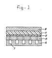
- Figure 1 shows a portion of a molten-carbonate cell in a cross-sectional view.
- 10 represents the electrolyte in the Li-Al-O 2 matrix
- 11 the LiCoO 2 cathode tape
- 12 the tape interlayer
- 13 the stainless steel current collector
- 14 the stainless steel corrugation plate.
- Figure 2 shows a first embodiment for employing double tape casting. This involves, as shown in Figure 2a, applying a layer 21 of tape material to a flat support 22.
- the tape material may comprise LiCoO 2 .
- a broad knife 23 is employed to ensure the homogeneous thickness of said tape layer. In so doing, the broad knife can either be moved across the layer of tape material 21, or the layer of tape material 21 can be moved past the knife together with the underlying supporting surface 22.
- the material from which an LiCoO 2 tape is cast is prepared in the following manner:
- LiCoO 2 powder, ethanol and tween surfactant are mixed together. Then methyl cellulose (binder material), demineralized water and TBP (solvent) are added, with continuous stirring.
- a drying cap is positioned over the cast tape in order to accomplish drying under optimal conditions.
- a thinner second tape 25 is applied in the same manner, as shown in Figure 2b. In so doing, a narrow knife 24 is used.
- the nickel suspension employed for tape casting in Figure 2b is prepared by mixing nickel powder, methyl cellulose, tween, TBP and ethanol. After some time, demineralized water is added and the mixture is stirred for half an hour.
- Figure 3 shows a second variation of double casting of a tape, such a double tape being produced in one step.
- An LiCoO 2 suspension is prepared in the above-described manner, as is a nickel suspension.
- the nickel-containing layer 25 is applied to the support 22, and then the electrode material 21 is placed on top of this.
- the right-hand side of the reservoir which contains LiCoO 2 here serves as a (narrow) knife.
- the double tape After the double tape has been produced, it is placed under a cap, in the above-described manner, and is then dried.
- Adhesion between the functional layer (or Ni layer) and the electrode layer (LiCoO 2 layer) obtained by means of the above method is so good that if the double tape is, for example, rolled up and unrolled again, the layers do not come apart. This is partly caused by the two materials, during casting, mixing to a small extent on the boundary layer and diffusing into each other. This is possible, inter alia, due to an identical solvent being used.
- a 100 cm 2 cell was assembled using LiCoO 2 tape as the cathode and, on top of this, an Ni tape according to the invention having a thickness of 50 pm, and in addition the customary components for a molten-carbonate fuel cell.
- the cell gave a good and stable performance, approximately 790 mV during the duration of the test of 1000 hours, which is not achieved without the interlayer. When the cell was taken apart it was found that during operation a firm contact with the current collector existed. No undesirable nickel deposits were found in the electrode or the electrolyte.
Landscapes
- Life Sciences & Earth Sciences (AREA)
- Engineering & Computer Science (AREA)
- Manufacturing & Machinery (AREA)
- Sustainable Development (AREA)
- Sustainable Energy (AREA)
- Chemical & Material Sciences (AREA)
- Chemical Kinetics & Catalysis (AREA)
- Electrochemistry (AREA)
- General Chemical & Material Sciences (AREA)
- Inert Electrodes (AREA)
- Fuel Cell (AREA)
- Battery Electrode And Active Subsutance (AREA)
Abstract
Description
Claims (8)
- Method for the fabrication of an electrochemical cell having an electrolyte based on molten carbonate, which comprises providing a cell stack, bringing it to an elevated temperature, wherein an electrode/current collector assembly is provided comprising an electrode to be sintered and a metallic current collector at placing a functional layer therebetween, characterized in that the electrode material employed is an LiCoO2-based material and in that the functional layer and the electrode, prior to being placed in the stack, are attached to each other.
- Method according to Claim 1, wherein the process of attaching to each other comprises providing either the electrode or the functional layer and applying thereonto, by means of the tape casting technique, either the functional layer or the electrode.
- Method according to Claim 2, wherein providing either the electrode or the functional layer comprises the fabrication of said part by means of a tape casting technique, immediately followed by the application of either the functional layer or the electrode.
- Method according to Claim 3, wherein a binder is used both during the fabrication of the green electrode and the green functional layer, and wherein the binder employed for the solvent is always based on the same material.
- Electrochemical cell containing green components, comprising green electrodes which are separated by a carbonate-based electrolyte which is liquid during operation, current collectors being disposed adjacent to the electrode and a functional layer being placed between at least one electrode and the current collector in question, characterized in that the electrode provided with the functional layer is based on LiCoO2, said functional layer being a green layer which contains a metal from the iron group.
- Electrochemical cell according to Claim 5, wherein the metal in the functional layer comprises Fe.
- Electrochemical cell according to Claim 5 or 6, wherein the thickness of the green functional layer is between 40 and 150 pm.
- Electrochemical cell according to any one of Claims 5-7, wherein the electrode provided with the functional layer comprises the cathode.
Applications Claiming Priority (3)
| Application Number | Priority Date | Filing Date | Title |
|---|---|---|---|
| NL9401481 | 1994-09-09 | ||
| NL9401481 | 1994-09-09 | ||
| PCT/NL1995/000306 WO1996008050A1 (en) | 1994-09-09 | 1995-09-08 | Double tape suitable for use in molten carbonate fuel cells |
Publications (2)
| Publication Number | Publication Date |
|---|---|
| EP0804812A1 EP0804812A1 (en) | 1997-11-05 |
| EP0804812B1 true EP0804812B1 (en) | 1999-01-07 |
Family
ID=19864644
Family Applications (1)
| Application Number | Title | Priority Date | Filing Date |
|---|---|---|---|
| EP95930058A Expired - Lifetime EP0804812B1 (en) | 1994-09-09 | 1995-09-08 | Double tape suitable for use in molten carbonate fuel cells |
Country Status (6)
| Country | Link |
|---|---|
| US (1) | US5885309A (en) |
| EP (1) | EP0804812B1 (en) |
| JP (1) | JP2960548B2 (en) |
| DE (1) | DE69507166T2 (en) |
| ES (1) | ES2129221T3 (en) |
| WO (1) | WO1996008050A1 (en) |
Families Citing this family (6)
| Publication number | Priority date | Publication date | Assignee | Title |
|---|---|---|---|---|
| DE19603918C2 (en) | 1996-02-03 | 2000-10-05 | Mtu Friedrichshafen Gmbh | Process for producing an electrode for a molten carbonate fuel cell and its use |
| NL1003238C2 (en) * | 1996-05-30 | 1997-12-03 | Stichting Energie | Method for manufacturing plate-shaped components or combinations of components. |
| NL1009815C2 (en) * | 1998-08-06 | 2000-02-15 | Stichting Energie | Method of manufacturing an MCFC electrochemical cell. |
| US6645657B2 (en) * | 2001-05-03 | 2003-11-11 | Fuelcell Energy, Inc. | Sol-gel coated cathode side hardware for carbonate fuel cells |
| US7060299B2 (en) * | 2002-12-31 | 2006-06-13 | Battelle Memorial Institute | Biodegradable microparticles that stabilize and control the release of proteins |
| WO2015054139A1 (en) * | 2013-10-08 | 2015-04-16 | Phillips 66 Company | Method of producing layers for solid oxide fuel cells |
Family Cites Families (5)
| Publication number | Priority date | Publication date | Assignee | Title |
|---|---|---|---|---|
| NL9001916A (en) * | 1990-08-30 | 1992-03-16 | Stichting Energie | TAPE SUITABLE FOR USE IN FUEL CELLS, ELECTRODE SUITABLE FOR USE IN A FUEL CELL, METHOD FOR SINTERING SUCH ELECTRODE AND FUEL CELL FITTED WITH SUCH ELECTRODE. |
| DE4030904A1 (en) * | 1990-09-29 | 1992-04-02 | Siemens Ag | METHOD FOR PRODUCING A CARBONATE MELT FUEL CELL STACK |
| DE4030944A1 (en) * | 1990-09-29 | 1992-04-02 | Siemens Ag | CARBONATE MELT FUEL CELL |
| JPH05335021A (en) * | 1992-05-29 | 1993-12-17 | Sumitomo Metal Mining Co Ltd | Air electrode for molten carbonate fuel cell and manufacturing method thereof |
| DE4303136C1 (en) * | 1993-02-04 | 1994-06-16 | Mtu Friedrichshafen Gmbh | Molten carbonate fuel cell - comprises matrix layer impregnated with molten electrolyte contg. lithium carbonate, having anode and cathode layers on either side |
-
1995
- 1995-09-08 US US08/793,846 patent/US5885309A/en not_active Expired - Fee Related
- 1995-09-08 JP JP8509400A patent/JP2960548B2/en not_active Expired - Lifetime
- 1995-09-08 ES ES95930058T patent/ES2129221T3/en not_active Expired - Lifetime
- 1995-09-08 WO PCT/NL1995/000306 patent/WO1996008050A1/en not_active Ceased
- 1995-09-08 EP EP95930058A patent/EP0804812B1/en not_active Expired - Lifetime
- 1995-09-08 DE DE69507166T patent/DE69507166T2/en not_active Expired - Fee Related
Also Published As
| Publication number | Publication date |
|---|---|
| WO1996008050A1 (en) | 1996-03-14 |
| DE69507166D1 (en) | 1999-02-18 |
| DE69507166T2 (en) | 1999-08-12 |
| ES2129221T3 (en) | 1999-06-01 |
| JP2960548B2 (en) | 1999-10-06 |
| EP0804812A1 (en) | 1997-11-05 |
| JPH09512950A (en) | 1997-12-22 |
| US5885309A (en) | 1999-03-23 |
Similar Documents
| Publication | Publication Date | Title |
|---|---|---|
| EP0514552B1 (en) | Method for manufacturing solid-state electrolytic fuel cell | |
| EP1501142B1 (en) | Fuel cell collector structure and solid oxide fuel cell stack using the same | |
| EP0670606A1 (en) | Solid oxide electrolyte fuel cell | |
| US11283084B2 (en) | Fabrication processes for solid state electrochemical devices | |
| US20030096155A1 (en) | Anode for molten carbonate fuel cell coated with porous ceramic films | |
| JPH08502851A (en) | High temperature fuel cell stack and manufacturing method thereof | |
| US5071717A (en) | Coated cathode substrate | |
| US5336276A (en) | Electrode having a conductive contact area and method of making the same | |
| US20060057281A1 (en) | Method for manufacturing membrane electrode assembly for fuel cell | |
| JPH07176317A (en) | Method for manufacturing electrode / ion-exchange thin film assembly, and method for manufacturing electrode / ion-exchange thin film / electrode assembly | |
| US5885309A (en) | Method of manufacturing an electrochemical cell | |
| JP2004214045A (en) | Fuel cell and its manufacturing method | |
| US11611088B2 (en) | Electrode assembly and method for its preparation | |
| EP2047547B1 (en) | Method of manufacturing a membrane-electrolyte assembly for fuel cells, and membrane-electrolyte assembly | |
| JP2006244913A (en) | Solid oxide fuel cell and method for producing the same | |
| KR101109011B1 (en) | Method for manufacturing cylindrical anode support electrolyte and cylindrical solid oxide fuel cell | |
| EP0473882B1 (en) | A method for manufacturing cathodes for molten carbonate cells | |
| JPH03134963A (en) | Solid electrolyte type fuel cell | |
| JPH05174832A (en) | Fuel electrode for high temperature solid electrolyte type fuel cell | |
| JPH0665036B2 (en) | Gas diffusion electrode and manufacturing method thereof | |
| CA3016512C (en) | Method for manufacturing fuel cell stack | |
| KR101165149B1 (en) | Electrode for a molten carbonate cell with dual pore structure | |
| JP2006222006A (en) | Solid oxide fuel cell and method for producing the same | |
| CN102201578B (en) | The method manufactured for membrane electrode assembly and membrane electrode assembly | |
| CN119852424B (en) | An ordered high-temperature proton exchange membrane fuel cell membrane electrode and its preparation method |
Legal Events
| Date | Code | Title | Description |
|---|---|---|---|
| PUAI | Public reference made under article 153(3) epc to a published international application that has entered the european phase |
Free format text: ORIGINAL CODE: 0009012 |
|
| 17P | Request for examination filed |
Effective date: 19970205 |
|
| AK | Designated contracting states |
Kind code of ref document: A1 Designated state(s): DE ES FR GB IT LU NL |
|
| GRAG | Despatch of communication of intention to grant |
Free format text: ORIGINAL CODE: EPIDOS AGRA |
|
| GRAG | Despatch of communication of intention to grant |
Free format text: ORIGINAL CODE: EPIDOS AGRA |
|
| 17Q | First examination report despatched |
Effective date: 19980323 |
|
| GRAG | Despatch of communication of intention to grant |
Free format text: ORIGINAL CODE: EPIDOS AGRA |
|
| GRAH | Despatch of communication of intention to grant a patent |
Free format text: ORIGINAL CODE: EPIDOS IGRA |
|
| GRAH | Despatch of communication of intention to grant a patent |
Free format text: ORIGINAL CODE: EPIDOS IGRA |
|
| GRAA | (expected) grant |
Free format text: ORIGINAL CODE: 0009210 |
|
| AK | Designated contracting states |
Kind code of ref document: B1 Designated state(s): DE ES FR GB IT LU NL |
|
| REF | Corresponds to: |
Ref document number: 69507166 Country of ref document: DE Date of ref document: 19990218 |
|
| ITF | It: translation for a ep patent filed | ||
| ET | Fr: translation filed | ||
| REG | Reference to a national code |
Ref country code: ES Ref legal event code: FG2A Ref document number: 2129221 Country of ref document: ES Kind code of ref document: T3 |
|
| PG25 | Lapsed in a contracting state [announced via postgrant information from national office to epo] |
Ref country code: LU Free format text: LAPSE BECAUSE OF NON-PAYMENT OF DUE FEES Effective date: 19990908 |
|
| PLBE | No opposition filed within time limit |
Free format text: ORIGINAL CODE: 0009261 |
|
| STAA | Information on the status of an ep patent application or granted ep patent |
Free format text: STATUS: NO OPPOSITION FILED WITHIN TIME LIMIT |
|
| 26N | No opposition filed | ||
| PGFP | Annual fee paid to national office [announced via postgrant information from national office to epo] |
Ref country code: GB Payment date: 20000821 Year of fee payment: 6 |
|
| PGFP | Annual fee paid to national office [announced via postgrant information from national office to epo] |
Ref country code: ES Payment date: 20000905 Year of fee payment: 6 |
|
| PGFP | Annual fee paid to national office [announced via postgrant information from national office to epo] |
Ref country code: FR Payment date: 20000918 Year of fee payment: 6 |
|
| PGFP | Annual fee paid to national office [announced via postgrant information from national office to epo] |
Ref country code: DE Payment date: 20001006 Year of fee payment: 6 |
|
| PG25 | Lapsed in a contracting state [announced via postgrant information from national office to epo] |
Ref country code: GB Free format text: LAPSE BECAUSE OF NON-PAYMENT OF DUE FEES Effective date: 20010908 |
|
| PG25 | Lapsed in a contracting state [announced via postgrant information from national office to epo] |
Ref country code: ES Free format text: LAPSE BECAUSE OF NON-PAYMENT OF DUE FEES Effective date: 20010909 |
|
| GBPC | Gb: european patent ceased through non-payment of renewal fee |
Effective date: 20010908 |
|
| PG25 | Lapsed in a contracting state [announced via postgrant information from national office to epo] |
Ref country code: DE Free format text: LAPSE BECAUSE OF NON-PAYMENT OF DUE FEES Effective date: 20020501 |
|
| PG25 | Lapsed in a contracting state [announced via postgrant information from national office to epo] |
Ref country code: FR Free format text: LAPSE BECAUSE OF NON-PAYMENT OF DUE FEES Effective date: 20020531 |
|
| REG | Reference to a national code |
Ref country code: FR Ref legal event code: ST |
|
| REG | Reference to a national code |
Ref country code: ES Ref legal event code: FD2A Effective date: 20021011 |
|
| PG25 | Lapsed in a contracting state [announced via postgrant information from national office to epo] |
Ref country code: IT Free format text: LAPSE BECAUSE OF NON-PAYMENT OF DUE FEES;WARNING: LAPSES OF ITALIAN PATENTS WITH EFFECTIVE DATE BEFORE 2007 MAY HAVE OCCURRED AT ANY TIME BEFORE 2007. THE CORRECT EFFECTIVE DATE MAY BE DIFFERENT FROM THE ONE RECORDED. Effective date: 20050908 |
|
| PGFP | Annual fee paid to national office [announced via postgrant information from national office to epo] |
Ref country code: NL Payment date: 20080924 Year of fee payment: 14 |
|
| REG | Reference to a national code |
Ref country code: NL Ref legal event code: V1 Effective date: 20100401 |
|
| PG25 | Lapsed in a contracting state [announced via postgrant information from national office to epo] |
Ref country code: NL Free format text: LAPSE BECAUSE OF NON-PAYMENT OF DUE FEES Effective date: 20100401 |