EP0804689B1 - Pre-tensioning device for fastening elements and method for pre-tensioning a fastening element - Google Patents
Pre-tensioning device for fastening elements and method for pre-tensioning a fastening elementInfo
- Publication number
- EP0804689B1 EP0804689B1 EP95901466A EP95901466A EP0804689B1 EP 0804689 B1 EP0804689 B1 EP 0804689B1 EP 95901466 A EP95901466 A EP 95901466A EP 95901466 A EP95901466 A EP 95901466A EP 0804689 B1 EP0804689 B1 EP 0804689B1
- Authority
- EP
- European Patent Office
- Prior art keywords
- shape
- memory metal
- fastening element
- tensioning
- piece
- Prior art date
- Legal status (The legal status is an assumption and is not a legal conclusion. Google has not performed a legal analysis and makes no representation as to the accuracy of the status listed.)
- Expired - Lifetime
Links
- 238000000034 method Methods 0.000 title claims description 7
- 229910052751 metal Inorganic materials 0.000 claims abstract description 80
- 239000002184 metal Substances 0.000 claims abstract description 80
- 230000009466 transformation Effects 0.000 claims abstract description 24
- 238000010438 heat treatment Methods 0.000 claims description 15
- 230000008859 change Effects 0.000 claims description 14
- 230000000694 effects Effects 0.000 claims description 12
- 238000001816 cooling Methods 0.000 claims description 4
- 230000001131 transforming effect Effects 0.000 claims 1
- 229910000831 Steel Inorganic materials 0.000 description 6
- 150000002739 metals Chemical class 0.000 description 6
- 239000010959 steel Substances 0.000 description 6
- 238000006243 chemical reaction Methods 0.000 description 3
- 229910000734 martensite Inorganic materials 0.000 description 3
- 229910001092 metal group alloy Inorganic materials 0.000 description 3
- 230000008878 coupling Effects 0.000 description 2
- 238000010168 coupling process Methods 0.000 description 2
- 238000005859 coupling reaction Methods 0.000 description 2
- 230000002441 reversible effect Effects 0.000 description 2
- 230000007704 transition Effects 0.000 description 2
- 230000001960 triggered effect Effects 0.000 description 2
- CURLTUGMZLYLDI-UHFFFAOYSA-N Carbon dioxide Chemical compound O=C=O CURLTUGMZLYLDI-UHFFFAOYSA-N 0.000 description 1
- 239000000654 additive Substances 0.000 description 1
- 230000008901 benefit Effects 0.000 description 1
- 230000005540 biological transmission Effects 0.000 description 1
- 235000011089 carbon dioxide Nutrition 0.000 description 1
- 239000013078 crystal Substances 0.000 description 1
- 230000005611 electricity Effects 0.000 description 1
- 238000003780 insertion Methods 0.000 description 1
- 230000037431 insertion Effects 0.000 description 1
- 230000002427 irreversible effect Effects 0.000 description 1
- 229910001000 nickel titanium Inorganic materials 0.000 description 1
- 230000002093 peripheral effect Effects 0.000 description 1
- 238000011084 recovery Methods 0.000 description 1
- 230000000717 retained effect Effects 0.000 description 1
- 230000035939 shock Effects 0.000 description 1
Images

Classifications
-
- B—PERFORMING OPERATIONS; TRANSPORTING
- B23—MACHINE TOOLS; METAL-WORKING NOT OTHERWISE PROVIDED FOR
- B23P—METAL-WORKING NOT OTHERWISE PROVIDED FOR; COMBINED OPERATIONS; UNIVERSAL MACHINE TOOLS
- B23P19/00—Machines for simply fitting together or separating metal parts or objects, or metal and non-metal parts, whether or not involving some deformation; Tools or devices therefor so far as not provided for in other classes
- B23P19/04—Machines for simply fitting together or separating metal parts or objects, or metal and non-metal parts, whether or not involving some deformation; Tools or devices therefor so far as not provided for in other classes for assembling or disassembling parts
- B23P19/06—Screw or nut setting or loosening machines
- B23P19/067—Bolt tensioners
- B23P19/068—Bolt tensioners by using heating means
-
- B—PERFORMING OPERATIONS; TRANSPORTING
- B25—HAND TOOLS; PORTABLE POWER-DRIVEN TOOLS; MANIPULATORS
- B25B—TOOLS OR BENCH DEVICES NOT OTHERWISE PROVIDED FOR, FOR FASTENING, CONNECTING, DISENGAGING OR HOLDING
- B25B29/00—Accessories
- B25B29/02—Bolt tensioners
-
- F—MECHANICAL ENGINEERING; LIGHTING; HEATING; WEAPONS; BLASTING
- F16—ENGINEERING ELEMENTS AND UNITS; GENERAL MEASURES FOR PRODUCING AND MAINTAINING EFFECTIVE FUNCTIONING OF MACHINES OR INSTALLATIONS; THERMAL INSULATION IN GENERAL
- F16B—DEVICES FOR FASTENING OR SECURING CONSTRUCTIONAL ELEMENTS OR MACHINE PARTS TOGETHER, e.g. NAILS, BOLTS, CIRCLIPS, CLAMPS, CLIPS OR WEDGES; JOINTS OR JOINTING
- F16B31/00—Screwed connections specially modified in view of tensile load; Break-bolts
- F16B31/04—Screwed connections specially modified in view of tensile load; Break-bolts for maintaining a tensile load
- F16B31/043—Prestressed connections tensioned by means of liquid, grease, rubber, explosive charge, or the like
-
- F—MECHANICAL ENGINEERING; LIGHTING; HEATING; WEAPONS; BLASTING
- F16—ENGINEERING ELEMENTS AND UNITS; GENERAL MEASURES FOR PRODUCING AND MAINTAINING EFFECTIVE FUNCTIONING OF MACHINES OR INSTALLATIONS; THERMAL INSULATION IN GENERAL
- F16B—DEVICES FOR FASTENING OR SECURING CONSTRUCTIONAL ELEMENTS OR MACHINE PARTS TOGETHER, e.g. NAILS, BOLTS, CIRCLIPS, CLAMPS, CLIPS OR WEDGES; JOINTS OR JOINTING
- F16B2200/00—Constructional details of connections not covered for in other groups of this subclass
- F16B2200/77—Use of a shape-memory material
-
- Y—GENERAL TAGGING OF NEW TECHNOLOGICAL DEVELOPMENTS; GENERAL TAGGING OF CROSS-SECTIONAL TECHNOLOGIES SPANNING OVER SEVERAL SECTIONS OF THE IPC; TECHNICAL SUBJECTS COVERED BY FORMER USPC CROSS-REFERENCE ART COLLECTIONS [XRACs] AND DIGESTS
- Y10—TECHNICAL SUBJECTS COVERED BY FORMER USPC
- Y10S—TECHNICAL SUBJECTS COVERED BY FORMER USPC CROSS-REFERENCE ART COLLECTIONS [XRACs] AND DIGESTS
- Y10S411/00—Expanded, threaded, driven, headed, tool-deformed, or locked-threaded fastener
- Y10S411/909—Fastener or fastener element composed of thermo-responsive memory material
-
- Y—GENERAL TAGGING OF NEW TECHNOLOGICAL DEVELOPMENTS; GENERAL TAGGING OF CROSS-SECTIONAL TECHNOLOGIES SPANNING OVER SEVERAL SECTIONS OF THE IPC; TECHNICAL SUBJECTS COVERED BY FORMER USPC CROSS-REFERENCE ART COLLECTIONS [XRACs] AND DIGESTS
- Y10—TECHNICAL SUBJECTS COVERED BY FORMER USPC
- Y10S—TECHNICAL SUBJECTS COVERED BY FORMER USPC CROSS-REFERENCE ART COLLECTIONS [XRACs] AND DIGESTS
- Y10S411/00—Expanded, threaded, driven, headed, tool-deformed, or locked-threaded fastener
- Y10S411/916—Bolt having tension feature
-
- Y—GENERAL TAGGING OF NEW TECHNOLOGICAL DEVELOPMENTS; GENERAL TAGGING OF CROSS-SECTIONAL TECHNOLOGIES SPANNING OVER SEVERAL SECTIONS OF THE IPC; TECHNICAL SUBJECTS COVERED BY FORMER USPC CROSS-REFERENCE ART COLLECTIONS [XRACs] AND DIGESTS
- Y10—TECHNICAL SUBJECTS COVERED BY FORMER USPC
- Y10S—TECHNICAL SUBJECTS COVERED BY FORMER USPC CROSS-REFERENCE ART COLLECTIONS [XRACs] AND DIGESTS
- Y10S411/00—Expanded, threaded, driven, headed, tool-deformed, or locked-threaded fastener
- Y10S411/917—Nut having tension feature
-
- Y—GENERAL TAGGING OF NEW TECHNOLOGICAL DEVELOPMENTS; GENERAL TAGGING OF CROSS-SECTIONAL TECHNOLOGIES SPANNING OVER SEVERAL SECTIONS OF THE IPC; TECHNICAL SUBJECTS COVERED BY FORMER USPC CROSS-REFERENCE ART COLLECTIONS [XRACs] AND DIGESTS
- Y10—TECHNICAL SUBJECTS COVERED BY FORMER USPC
- Y10T—TECHNICAL SUBJECTS COVERED BY FORMER US CLASSIFICATION
- Y10T29/00—Metal working
- Y10T29/49—Method of mechanical manufacture
- Y10T29/49826—Assembling or joining
- Y10T29/49863—Assembling or joining with prestressing of part
- Y10T29/49865—Assembling or joining with prestressing of part by temperature differential [e.g., shrink fit]
Definitions
- the invention relates to a pre-tensioning device for a screw or the like fastening element, which is used in engineering particularly when the purpose is to pre-tension large screws during an assembling operation.
- the pre-tensioning is carried out by stretching the screw using a certain pre-calculated force before a nut is screwed tight.
- some pre-tensioning tools have been developed, of which for instance hydraulic pre-tensioning devices can be mentioned, one example being Swedish publication 7701049-4, where a screw is stretched by means of hydraulic pressure and thereafter the nut is screwed down. After removing the pressure, the coupling will be tightened and the desired pre-stress will remain in the screw.
- the streching takes place at the end of the screw to be stretched, but often also a piston-like part is placed in a hole bored inside the screw, and hydraulic pressure can be exerted on one end of the piston-like part.
- the stretching force will be directed by the contribution of the piston directly to the screw ends, between which the pre-tensioning elongation will thus be present.
- German publication DE-OS 3733243 is used a piston element which is placed within a hole bored inside a screw and which can also be heated.
- a steel rod placed within a screw is used, being heatable for instance with electric current, whereby the rod will stretch the screw to be pre-tensioned through the thermal expansion caused by the heat introduced therein. All above-mentioned methods require complicated devices and tools, which often have to be manufactured each for the respective screw size.
- U.S. Patent 5,248,233 discloses a sort of releasing device for a screw coupling, employing a phase change of a shape-memory metal cylinder provided with a heating element to release a segmented nut without causing a shock effect on the structure. This patent shows no pre-tensioning for performing a fastening operation.
- U.S. Patent 4,450,616 comprises a shape-memory metal disc utilizing the properties of the shape-memory metal only for ensuring the tightness of a nut or a screw.
- the device according to the invention is based on the use of shape-memory metals known as such.
- the invention is based on a phase transformation occurring in the crystal structure of the shape-memory metal, effected by temperature.
- the phenomenon is called martensitic reaction.
- the shapes and volumes of pieces made of shape-memory metal alloys are recovered exactly to correspond to the original status at a relatively low temperature on heating after a deformation caused by an external force. The recovery is complete typically still after a deformation of 4-8%.
- the martensitic reaction starts and takes place in a quite narrow transition temperature range of typically ca. 20°C (range A s to A f ), which can usually be fitted in a desired area within the temperature range of -30...+100°C. On certain conditions, the martensitic reaction is crystallographically completely reversible.
- shape-memory metals are not based on thermal expansion, but on a phase change in the crystalline structure triggered by a temperature change.
- the transformation takes place quickly once the transformation temperature has been attained. Because of the low transformation temperature, the piece to be heated does not require large amounts of heat.
- the shape-memory metals exist as two main groups, whereof one shows a one-way shape-memory effect and the other a two-way effect. Those shape-memory metals based on the one-way shape-memory effect, the deformation triggered by a predetermined transformation temperature is irreversible. In the case of the two-way shape-memory effect, the deformation is reversible as the piece is being cooled below a predetermined temperature (range M s to M f ).
- a shape-memory metal based on the one-way shape-memory effect is designated one-way shape-memory metal
- a shape-memory metal based on the two-way shape-memory effect is designated two-way shape-memory metal
- the temperatures are designated upper transformation temperature (A f ) and respectively lower transformation temperature (M f ).
- a two-way shape-memory metal has the upper transformation temperature typically within the range of 80 to 100°C, and the piece will not recover its original state until the piece cools or is cooled to the lower transformation temperature, which is typically in the range of -20°C to +20°C.
- the above-mentioned cycle can be repeated several times, even to the extent of 10 000 times depending on the deformation and load.
- shape-memory metal alloys can withstand very high stresses without plasticizing and losing their shape-memory characteristics, even 800 to 1000 N/mm 2 , and consequently a piece made of such metal can produce large forces in connection with the deformation.
- the phase change starting within the pre-determined transition temperature range of the so-called shape-memory metal is used as the source of stretching power for a fastening element, this change causing a dimensional change in the shape-memory metal piece.
- the force occurring in association with this dimensional change is used for the stretching of the fastening element.
- the deformation capacity of a two-way shape-memory metal is typically ca. 4%, whereas a pre-stress elongation of for example a steel screw is typically ca. 0.2% of the elongation length.
- the fastening element is understood to mean a fastening element, as a rule of elongate shape, stretchable upon application of a force and tightenable to a fixed relation to parts to be joined by means of a tightening member movable in the longitudinal direction of the fastening element.
- the fastening element is freely expandable at least relative to a first piece to be joined, on which the tightening member abuts, and its movement is limited in the stretching direction relative to the second piece to be joined at least when the tightening member is tightened against the first piece.
- the parts 1a, 1b to be joined together are connected by means of a screw 2 acting as the fastening element.
- the screw is shown engaged through a threading 8 with the lower one 1b of the pieces to be joined together and to pass through the upper piece 1a.
- a tightening member for instance a nut 3
- a locking piece 5 inside which the nut 3 has space to move freely.
- annular sleeve 4 manufactured of a two-way shape-memory metal.
- the locking piece 5 and the sleeve 4 together form a pre-tensioning unit where the locking piece 5 acts as a retaining piece receiving the effects which are due to changes in the sleeve 4 and transmits them further to the screw 2.
- the device operates in the following way:
- the sleeve 4 is heated in some way, for example with a heating fan, to the upper transformation temperature, whereby a phase change occurs therein and it expands also in the direction of the screw and through the locking piece 5 will stretch the screw 2 which is able to expand relative to the first piece 1a to be joined.
- the nut 3 can be tightened at recesses 10 in the nut 3 using a tool known as such by insertion through openings 7 in the locking piece 5.
- the shape-memory metal sleeve 4 is allowed to cool or it is cooled to the lower transformation temperature, whereby the sleeve 4 recovers its original dimensions and the screw is tightened.
- the locking piece 5 can now be released and the shape-memory metal sleeve 4 is removed.
- the shape-memory metal sleeve can be dimensioned separately for each screw length and each force required for stretching the screw. However, most practical is to dimension the sleeve to have such thickness that it will be sufficient for stretching screws of various lengths up to a pre-determined maximum length. If the expansion required for the pre-tensioned screw is smaller than the expansion of the shape-memory metal sleeve 4, a clearance 11 is left between the shape-memory metal sleeve 4 and the edge portion 13 of the locking piece, the clearance being so dimensioned that the expansion of the shape-memory metal sleeve minus the dimension of the clearance equals the required pre-tensioning expansion of the screw. The clearance can be measured by means of some well-known measuring instrument.
- the shape-memory metal sleeve 4 can be heated to the upper transformation temperature in a well-known way by using for example a heating fan or electric resistance, which can be disposed ready around the sleeve. Because the transformation temperature is relatively low, the amount of the necessary heat is not very large. A sleeve made of a two-way shape-memory metal reverts to its original shape as its temperature drops below the lower transformation temperature. If this temperature lies below the ambient temperature, the cooling to the lower transformation temperature can take place for example with dry ice.
- the device according to the invention has the significant advantage that it allows to use usual screws with heads or tenons. Also the space required by the devices for performing the pre-tensioning is small. No measuring devices are necessarily needed for performing the pre-tensioning. The screw can be released using the same device.
- the device can be used for pre-tensioning screws of several sizes.
- the sleeve can also be divided in its peripheral direction into several sections.
- the locking piece 5 instead of the skirt-like edge portion 13, the locking piece 5 comprises two or several separate legs directed towards the part 1a to be joined, under which legs the shape-memory metal pieces are placed.
- the shape-memory metal piece can also be fastened to the locking piece 5 in such a way that the pieces are retained together.
- Figure 3 shows another alternative which employs a pre-tensioning unit supported by the bottom of a hole located inside the fastening element.
- a hole 15 has been bored in the center of the screw 2 to be pre-tensioned and it receives a shape-memory metal cartridge 4.
- a heating element 16 which can be for instance an electric resistance heatable by electricity.
- a restrictor screw 5 acting as a retaining piece can be fastened in an internal threading 17 on one end of the screw on the mouth side of the hole 15.
- the restrictor screw will hereinafter be designated restrictor.
- the electric wires 19 to the cartridge 4 pass through the restrictor along a hole 18 bored therein.
- the hole 15 bored in the screw 2 extends mainly over the area which should be expanded during the pre-tensioning of the screw 2.
- the device operates in the following way:
- the screw 2 to be pre-tensioned is mounted in its place and the shape-memory metal cartridge 4 is placed in the screw hole 15.
- the restrictor is rotated into the threading 17 in such a fashion that the wires 19 for the heating element 16 of the cartridge pass through the hole 18 of the restrictor 5.
- a clearance 11 can be left between the cartridge 4 and the restrictor 5, the clearance being so dimensioned that the change of length of the shape-memory metal cartridge 4 minus the clearance equals the desired elongation of the screw.
- the shape-memory metal cartridge 4 When the shape-memory metal cartridge 4 is heated by the heating element 16 to the upper transformation temperature, a deformation in the form of length increase of the cartridge will take place, which in turn through the bottom 20 of the hole 15 and through the restrictor 5 stretches the screw 2. While the screw is in the streched state, the nut 3 is tightened. As the shape-memory metal cartridge 4 cools to the lower transformation temperature, it reverts to its original dimension, and the screw 2 has been pre-tensioned. The restrictor 5 and the cartridge 4 can now be removed. The releasing of the screw 2 is carried out in an analogous manner.
- the screw 2 is heated by an electric resistance. It is apparent for a man skilled in the art that the heating can take place also in some other known way.
- the shape-memory metal cartridge 4 can be separately dimensioned for each screw length and each force required for the stretching of the screw 2. It is, however, practical that the cartridge is dimensioned to have such length that it is sufficient for stretching a screw of a given length. If the elongation required for the screw to be pre-tensioned is smaller than the elongation of the shape-memory metal cartridge 4, a clearance 11 can be left between the shape-memory metal cartridge 4 and the restrictor, and so the same cartridge can be used for pretightening of screws of several sizes. The clearance can be measured by first screwing the restrictor 5 down and thereafter by opening it by a given number of revolutions or by measuring the extent of protrusion of the restrictor in some well-known manner.
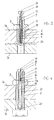
- Figure 4 shows a third alternative for performing the pre-tensioning operation.
- a restrictor 5 is rotated in the internal threading 17 on the mouth portion of a hole 15 located at one end of the screw 2 to be pre-tensioned.
- a shape-memory metal cartridge 4 In a non-threaded extension 17a of the mouth portion is placed a shape-memory metal cartridge 4. From the cartridge 4 extends a metal rod 21 placed within the bore 15 extending inside the screw, the purpose of which rod is to transmit the force caused by the deformation of the shape-memory metal cartridge to the other end of the screw 2 through the bottom 20 of the bore.
- the device operates in the same manner as described hereinbefore.
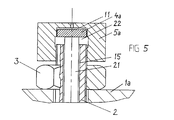
- Figure 5 shows a fourth alternative where the shape-memory metal cartridge 4 is deplaced outside the screw hole and for example a steel rod 21 has been placed in the hole.
- the steel rod is longer than the hole bored in the screw 2 and so dimensioned that it will withstand the force required for stretching the screw 2.
- a nut 3 and thereafter a restrictor nut 5a corresponding to the restrictor 5 of Fig. 3 have been rotated at the end of the screw 2 on its threading, the former being designated hereinafter restrictor and accommodating in its interior at least one cylindrical shape-memory metal piece 4a corresponding to the shape-memory metal cartridge 4 of Fig. 3. The piece abuts on the rod 21 and on its other side on the restrictor 5a.
- the heating of the shape-memory metal cylinder 4a to the upper transformation temperature can take place by means of a heating element placed inside it or the heating element can be placed in a space 22 inside the restrictor.
- the heating can be performed also by heating the restrictor 5a from the outside, whereby the heat will be conducted along the restrictor to the shape-memory metal cylinder 4a starting there the desired phase change, which causes the transformation giving rise to a expansion force for the screw 2, the force being transmitted from the shape-memory metal cylinder 4a through the restrictor 5a to one end of the screw 2, as well as through the rod 21 to the other end of the screw 2, thus stretching the screw.
- the nut 13 is screwed down onto the first piece 1a to be joined, relative to which the screw has been able to expand freely, the operation being performed in the same way as in Figs. 3 and 4.
- the shape-memory metal cylinder 4a After the shape-memory metal cylinder 4a has been cooled, or during its cooling to the lower transformation temperature, it recovers its original dimensions, and the pre-tensioning means, the restrictor 5a, the shape-memory metal cylinder 4a, the possible heating element and the rod 21, can be removed. The releasing of the screw takes place in an analogous manner.
- a shape-memory metal cartridge 4, 4a made of a one-way shape-memory metal is used in the device, it is difficult to remove it after the pre-tensioning. If a cartridge made of a two-way shape-memory metal is used, it can be easily removed after the pre-tensioning of the cartridge and it can be used again for pre-tensioning of other screws. The same applies to the removal of the shape-memory metal piece from the pre-tensioning device of Figs. 1 and 2. However, the phenomena taking place during the cooling, such as relaxation and thermal shrinkage, can facilitate the removal of the pre-tensioning device also in case of one-way shape-memory metals.
- the shape-memory metals are usually metal alloys, and they are known in a variety of types, for instance a nickel-titanium alloy mixed with additives.
- the invention is not limited to any single well-known or later discovered shape-memory metal.
Landscapes
- Engineering & Computer Science (AREA)
- Mechanical Engineering (AREA)
- General Engineering & Computer Science (AREA)
- Connection Of Plates (AREA)
- Formation And Processing Of Food Products (AREA)
- Dowels (AREA)
- Clamps And Clips (AREA)
- Forging (AREA)
- Hand Tools For Fitting Together And Separating, Or Other Hand Tools (AREA)
- Flanged Joints, Insulating Joints, And Other Joints (AREA)
- Reinforcement Elements For Buildings (AREA)
- Heat Treatment Of Articles (AREA)
Abstract
Description
- The invention relates to a pre-tensioning device for a screw or the like fastening element, which is used in engineering particularly when the purpose is to pre-tension large screws during an assembling operation.
- It is preferred that the pre-tensioning is carried out by stretching the screw using a certain pre-calculated force before a nut is screwed tight. For performing this step, some pre-tensioning tools have been developed, of which for instance hydraulic pre-tensioning devices can be mentioned, one example being Swedish publication 7701049-4, where a screw is stretched by means of hydraulic pressure and thereafter the nut is screwed down. After removing the pressure, the coupling will be tightened and the desired pre-stress will remain in the screw.
- In the above-mentioned case, the streching takes place at the end of the screw to be stretched, but often also a piston-like part is placed in a hole bored inside the screw, and hydraulic pressure can be exerted on one end of the piston-like part. Hereby the stretching force will be directed by the contribution of the piston directly to the screw ends, between which the pre-tensioning elongation will thus be present.
- In German publication DE-OS 3733243 is used a piston element which is placed within a hole bored inside a screw and which can also be heated. In some cases, a steel rod placed within a screw is used, being heatable for instance with electric current, whereby the rod will stretch the screw to be pre-tensioned through the thermal expansion caused by the heat introduced therein. All above-mentioned methods require complicated devices and tools, which often have to be manufactured each for the respective screw size.
- U.S. Patent 5,248,233 discloses a sort of releasing device for a screw coupling, employing a phase change of a shape-memory metal cylinder provided with a heating element to release a segmented nut without causing a shock effect on the structure. This patent shows no pre-tensioning for performing a fastening operation.
- U.S. Patent 4,450,616 comprises a shape-memory metal disc utilizing the properties of the shape-memory metal only for ensuring the tightness of a nut or a screw.
- In the pre-tensioning device according to the invention, most drawbacks associated with the present devices have been eliminated. The device according to the invention is based on the use of shape-memory metals known as such.
- The invention is based on a phase transformation occurring in the crystal structure of the shape-memory metal, effected by temperature. The phenomenon is called martensitic reaction. The shapes and volumes of pieces made of shape-memory metal alloys are recovered exactly to correspond to the original status at a relatively low temperature on heating after a deformation caused by an external force. The recovery is complete typically still after a deformation of 4-8%. The martensitic reaction starts and takes place in a quite narrow transition temperature range of typically ca. 20°C (range As to Af), which can usually be fitted in a desired area within the temperature range of -30...+100°C. On certain conditions, the martensitic reaction is crystallographically completely reversible. The deformations of shape-memory metals are not based on thermal expansion, but on a phase change in the crystalline structure triggered by a temperature change. The transformation takes place quickly once the transformation temperature has been attained. Because of the low transformation temperature, the piece to be heated does not require large amounts of heat.
- The shape-memory metals exist as two main groups, whereof one shows a one-way shape-memory effect and the other a two-way effect. Those shape-memory metals based on the one-way shape-memory effect, the deformation triggered by a predetermined transformation temperature is irreversible. In the case of the two-way shape-memory effect, the deformation is reversible as the piece is being cooled below a predetermined temperature (range Ms to Mf). Hereinafter a shape-memory metal based on the one-way shape-memory effect is designated one-way shape-memory metal, and a shape-memory metal based on the two-way shape-memory effect is designated two-way shape-memory metal, and the temperatures are designated upper transformation temperature (Af) and respectively lower transformation temperature (Mf).
- A two-way shape-memory metal has the upper transformation temperature typically within the range of 80 to 100°C, and the piece will not recover its original state until the piece cools or is cooled to the lower transformation temperature, which is typically in the range of -20°C to +20°C. The above-mentioned cycle can be repeated several times, even to the extent of 10 000 times depending on the deformation and load.
- Several shape-memory metal alloys can withstand very high stresses without plasticizing and losing their shape-memory characteristics, even 800 to 1000 N/mm2, and consequently a piece made of such metal can produce large forces in connection with the deformation.
- In a device according to the invention, the phase change starting within the pre-determined transition temperature range of the so-called shape-memory metal is used as the source of stretching power for a fastening element, this change causing a dimensional change in the shape-memory metal piece. The force occurring in association with this dimensional change is used for the stretching of the fastening element. The deformation capacity of a two-way shape-memory metal is typically ca. 4%, whereas a pre-stress elongation of for example a steel screw is typically ca. 0.2% of the elongation length.
- In the following, the invention will be described in more detail with reference to the accompanying drawings, wherein
- Fig. 1
- shows an arrangement and a device according to the invention for pre-tensioning a screw,
- Fig. 2
- shows a locking piece and an actual tightening element according to the invention of Fig. 1,
- Fig. 3
- shows another device designed for pre-tensioning of a fastening element according to the invention, utilizing a shape-memory metal cartridge placed inside the fastening element for pre-tensioning,
- Fig. 4
- shows a third altemative according to the invention for performing pre-tensioning by means of a shape-memory metal cartridge, whereby a part of the cartridge is replaced with a steel rod, and
- Fig. 5
- a fourth application according to the invention where the shape-memory metal cartridge is placed outside a hole of the fastening element and with a steel rod placed in the hole for transmission of force.
- In the invention, the fastening element is understood to mean a fastening element, as a rule of elongate shape, stretchable upon application of a force and tightenable to a fixed relation to parts to be joined by means of a tightening member movable in the longitudinal direction of the fastening element. The fastening element is freely expandable at least relative to a first piece to be joined, on which the tightening member abuts, and its movement is limited in the stretching direction relative to the second piece to be joined at least when the tightening member is tightened against the first piece.
- In the arrangement according to Fig. 1, the
parts screw 2 acting as the fastening element. In the case presented by Fig. 1, the screw is shown engaged through athreading 8 with the lower one 1b of the pieces to be joined together and to pass through theupper piece 1a. On a threading 9 at the upper end of the screw is rotated a tightening member, for instance anut 3, and on top of it on the same threading alocking piece 5, inside which thenut 3 has space to move freely. Between a skirt-like edge portion 13 of thelocking piece 5 and thepiece 1a to be fastened is placed anannular sleeve 4 manufactured of a two-way shape-memory metal. Thelocking piece 5 and thesleeve 4 together form a pre-tensioning unit where thelocking piece 5 acts as a retaining piece receiving the effects which are due to changes in thesleeve 4 and transmits them further to thescrew 2. - The device operates in the following way: The
sleeve 4 is heated in some way, for example with a heating fan, to the upper transformation temperature, whereby a phase change occurs therein and it expands also in the direction of the screw and through thelocking piece 5 will stretch thescrew 2 which is able to expand relative to thefirst piece 1a to be joined. Thereafter thenut 3 can be tightened atrecesses 10 in thenut 3 using a tool known as such by insertion throughopenings 7 in thelocking piece 5. After tightening thenut 3, the shape-memory metal sleeve 4 is allowed to cool or it is cooled to the lower transformation temperature, whereby thesleeve 4 recovers its original dimensions and the screw is tightened. Thelocking piece 5 can now be released and the shape-memory metal sleeve 4 is removed. - The shape-memory metal sleeve can be dimensioned separately for each screw length and each force required for stretching the screw. However, most practical is to dimension the sleeve to have such thickness that it will be sufficient for stretching screws of various lengths up to a pre-determined maximum length. If the expansion required for the pre-tensioned screw is smaller than the expansion of the shape-
memory metal sleeve 4, aclearance 11 is left between the shape-memory metal sleeve 4 and theedge portion 13 of the locking piece, the clearance being so dimensioned that the expansion of the shape-memory metal sleeve minus the dimension of the clearance equals the required pre-tensioning expansion of the screw. The clearance can be measured by means of some well-known measuring instrument. - The shape-
memory metal sleeve 4 can be heated to the upper transformation temperature in a well-known way by using for example a heating fan or electric resistance, which can be disposed ready around the sleeve. Because the transformation temperature is relatively low, the amount of the necessary heat is not very large. A sleeve made of a two-way shape-memory metal reverts to its original shape as its temperature drops below the lower transformation temperature. If this temperature lies below the ambient temperature, the cooling to the lower transformation temperature can take place for example with dry ice. - The device according to the invention has the significant advantage that it allows to use usual screws with heads or tenons. Also the space required by the devices for performing the pre-tensioning is small. No measuring devices are necessarily needed for performing the pre-tensioning. The screw can be released using the same device.
- By providing the
locking piece 5 with several adaptor rings 12, where the intemal threading 6 is adapted to thecorresponding threading 9 of thescrew 2 and the adaptor piece is fastened through anexternal threading 14 to theedge portion 13 of thelocking piece 5, the device can be used for pre-tensioning screws of several sizes. - It is apparent for a man skilled in the art that if a long screw is to be pre-tensioned and the deformation of one single shape-memory metal sleeve is not sufficient to give the screw the required pre-tensioning expansion, two or several shape-
memory metal sleeves 4 can be placed beneath the locking piece on top of each other. The sleeves can then have standard heights, which allows to obtain the desired expansion required in the pre-tensioning by application of one or several sleeves one on top of the other. - The sleeve can also be divided in its peripheral direction into several sections. In this case it is preferred that instead of the skirt-
like edge portion 13, thelocking piece 5 comprises two or several separate legs directed towards thepart 1a to be joined, under which legs the shape-memory metal pieces are placed. - The shape-memory metal piece can also be fastened to the
locking piece 5 in such a way that the pieces are retained together. - Figure 3 shows another alternative which employs a pre-tensioning unit supported by the bottom of a hole located inside the fastening element. A
hole 15 has been bored in the center of thescrew 2 to be pre-tensioned and it receives a shape-memory metal cartridge 4. Inside the cartridge is placed aheating element 16, which can be for instance an electric resistance heatable by electricity. Arestrictor screw 5 acting as a retaining piece can be fastened in aninternal threading 17 on one end of the screw on the mouth side of thehole 15. The restrictor screw will hereinafter be designated restrictor. Theelectric wires 19 to thecartridge 4 pass through the restrictor along ahole 18 bored therein. - The
hole 15 bored in thescrew 2 extends mainly over the area which should be expanded during the pre-tensioning of thescrew 2. - The device operates in the following way: The
screw 2 to be pre-tensioned is mounted in its place and the shape-memory metal cartridge 4 is placed in thescrew hole 15. The restrictor is rotated into the threading 17 in such a fashion that thewires 19 for theheating element 16 of the cartridge pass through thehole 18 of therestrictor 5. By rotating suitably the restrictor, aclearance 11 can be left between thecartridge 4 and therestrictor 5, the clearance being so dimensioned that the change of length of the shape-memory metal cartridge 4 minus the clearance equals the desired elongation of the screw. When the shape-memory metal cartridge 4 is heated by theheating element 16 to the upper transformation temperature, a deformation in the form of length increase of the cartridge will take place, which in turn through the bottom 20 of thehole 15 and through therestrictor 5 stretches thescrew 2. While the screw is in the streched state, thenut 3 is tightened. As the shape-memory metal cartridge 4 cools to the lower transformation temperature, it reverts to its original dimension, and thescrew 2 has been pre-tensioned. Therestrictor 5 and thecartridge 4 can now be removed. The releasing of thescrew 2 is carried out in an analogous manner. - In the description above, the
screw 2 is heated by an electric resistance. It is apparent for a man skilled in the art that the heating can take place also in some other known way. - The shape-
memory metal cartridge 4 can be separately dimensioned for each screw length and each force required for the stretching of thescrew 2. It is, however, practical that the cartridge is dimensioned to have such length that it is sufficient for stretching a screw of a given length. If the elongation required for the screw to be pre-tensioned is smaller than the elongation of the shape-memory metal cartridge 4, aclearance 11 can be left between the shape-memory metal cartridge 4 and the restrictor, and so the same cartridge can be used for pretightening of screws of several sizes. The clearance can be measured by first screwing therestrictor 5 down and thereafter by opening it by a given number of revolutions or by measuring the extent of protrusion of the restrictor in some well-known manner. - Figure 4 shows a third alternative for performing the pre-tensioning operation. A
restrictor 5 is rotated in the internal threading 17 on the mouth portion of ahole 15 located at one end of thescrew 2 to be pre-tensioned. In anon-threaded extension 17a of the mouth portion is placed a shape-memory metal cartridge 4. From thecartridge 4 extends ametal rod 21 placed within thebore 15 extending inside the screw, the purpose of which rod is to transmit the force caused by the deformation of the shape-memory metal cartridge to the other end of thescrew 2 through the bottom 20 of the bore. The device operates in the same manner as described hereinbefore. - Figure 5 shows a fourth alternative where the shape-
memory metal cartridge 4 is deplaced outside the screw hole and for example asteel rod 21 has been placed in the hole. The steel rod is longer than the hole bored in thescrew 2 and so dimensioned that it will withstand the force required for stretching thescrew 2. Anut 3 and thereafter arestrictor nut 5a corresponding to therestrictor 5 of Fig. 3 have been rotated at the end of thescrew 2 on its threading, the former being designated hereinafter restrictor and accommodating in its interior at least one cylindrical shape-memory metal piece 4a corresponding to the shape-memory metal cartridge 4 of Fig. 3. The piece abuts on therod 21 and on its other side on the restrictor 5a. The heating of the shape-memory metal cylinder 4a to the upper transformation temperature can take place by means of a heating element placed inside it or the heating element can be placed in aspace 22 inside the restrictor. The heating can be performed also by heating therestrictor 5a from the outside, whereby the heat will be conducted along the restrictor to the shape-memory metal cylinder 4a starting there the desired phase change, which causes the transformation giving rise to a expansion force for thescrew 2, the force being transmitted from the shape-memory metal cylinder 4a through the restrictor 5a to one end of thescrew 2, as well as through therod 21 to the other end of thescrew 2, thus stretching the screw. After thescrew 2 has been pre-tensioned in this way, thenut 13 is screwed down onto thefirst piece 1a to be joined, relative to which the screw has been able to expand freely, the operation being performed in the same way as in Figs. 3 and 4. After the shape-memory metal cylinder 4a has been cooled, or during its cooling to the lower transformation temperature, it recovers its original dimensions, and the pre-tensioning means, therestrictor 5a, the shape-memory metal cylinder 4a, the possible heating element and therod 21, can be removed. The releasing of the screw takes place in an analogous manner. - It is also possible to use a
clearance 11 in the embodiment according to Fig. 5 so that the deformation of the shape-memory metal cartridge 4 or cylinder 4a and the desired screw expansion can be matched to each other, as explained hereinbefore. - In the embodiment according to Fig. 5, also two or several corresponding or also variable-length cylinders can be placed on top of each other instead of one single shape-memory metal cartridge 4a, and in this way their joined transformation can be matched to the expansion desired for the
screw 2. - In case a shape-
memory metal cartridge 4, 4a made of a one-way shape-memory metal is used in the device, it is difficult to remove it after the pre-tensioning. If a cartridge made of a two-way shape-memory metal is used, it can be easily removed after the pre-tensioning of the cartridge and it can be used again for pre-tensioning of other screws. The same applies to the removal of the shape-memory metal piece from the pre-tensioning device of Figs. 1 and 2. However, the phenomena taking place during the cooling, such as relaxation and thermal shrinkage, can facilitate the removal of the pre-tensioning device also in case of one-way shape-memory metals. - It is apparent for a man skilled in the art that the invention can also be applied for pre-tensioning other fastening means than those described in the figures and the description, and it is not essential for the function of the device, in which way the heat is brought to the shape-memory metal cartridge.
- The shape-memory metals are usually metal alloys, and they are known in a variety of types, for instance a nickel-titanium alloy mixed with additives. The invention is not limited to any single well-known or later discovered shape-memory metal.
Claims (14)
- Pre-tensioning device for fastening, comprising a pre-tensioning unit (4,5) having a first part (5) attached to one end of a fastening element (2) at a first region and having a second part (4) adjacent the first part, together with a tightening member (3), which is a member separate from the pre-tensioning unit (4, 5) and attached to the fastening element (2) to be mobile independently of the pre-tensioning unit, the other end of the fastening element being attachable to a piece (1b) limiting the movement of the fastening element (2) in the direction of expansion, wherein the second part (4) of the pre-tensioning unit (4, 5) comprises shape-memory metal and is designed to expand through a phase change so as to act on the first part (5) to stretch the fastening element and allow the tightening member (3) to be moved to the tightening position towards a second piece (1a) to be joined to the first piece (1b) by means of the fastening element, before the stretching effect of the shape memory metal is removed.
- Pre-tensioning device according to claim 1, characterized in that the first part (5) comprises a retaining part (5) attached at the first region, and the part of shape-memory metal (4; 4a) is located between the retaining part and a rigid part (1a, 20).
- Pre-tensioning device according to claim 1 or 2, characterized in that the shape-memory metal is a two-way shape-memory metal having at least the upper transforming temperature above the mounting temperature of the pre-tensioning unit.
- Pre-tensioning device according to claim 1, 2 or 3, characterized in that the first part comprises a locking part (5) placed over a tightening member, such as a nut (3), movable along a threading, said locking part being placed on the same threading and being supportable through its edge portion (13) directed towards said piece (1a) to be joined.
- Device according to claims 2 and 4, characterized in that placed in association with the edge portion (13) of the locking part there is the second part (4) made of shape-memory metal, such as a sleeve or separate pieces.
- Device as claimed in claim 4 or 5, characterized in that the locking part (5) has an adaptor ring (12) to fit it to the threading of the fastening element (1) to be pre-tensioned, the locking part (5) further comprising an edge portion (13) attachable to the adaptor ring (12).
- Device according to claim 5 or 6, characterized in that the part (4) of shape-memory metal is attached to the locking part (5).
- Device according to claim 2 or 3, characterized in that in a space limited by a hole (15) bored inside the fastening element (2) to be pre-tensioned and by a restrictor (5, 5a) attached on the end of the fastening element there is a cartridge (4; 4a) made of shape-memory metal and designed to perform the pre-tensioning.
- Device according to claim 8, characterized in that the cartridge (4; 4a) abuts at its one end on the restrictor (5; 5a) and at its other end on a rod (21) passing as an extension of the cartridge down to the bottom (20) of the hole.
- Device according to claim 8 or 9, characterized in that the cartridge is provided with a heating element (16), to which the heat energy is brought for instance through the restrictor (5; 5a).
- Method for pre-tensioning using a device according to claim 1, in which method the other end of the fastening element is passed through the second piece (1a) and attached to the first piece (1b) the shape-memory metal is heated to its transformation temperature where it expands through a phase change and acts on the first part (5) to stretch the fastening element, the tightening member (3) attached to the fastening element (2) is tightened by movement towards the second piece (1a), whereafter the stretching effect of the shape memory metal is removed so that fastening element (2) is tightened finally.
- Method according to claim 11, characterized in that the shape-memory metal is a two-way shape-memory metal, the pre-tensioning effect of the shape-memory metal being removed by cooling it or allowing it to cool to its lower transformation temperature.
- Method according to claim 11 or 12, characterized in that a retaining part (5) is attached to the fastening element (2), and the pre-tensioning is effected by means of the second part (4) of shape-memory metal being located between the retaining part and a rigid part (1a; 20).
- Method according to claim 13, characterized in that a desired pre-tensioning elongation in the fastening element (2) and the expansion change of the shape-memory metal piece (4) are matched together by leaving a clearance (11) between the shape-memory metal part (4) and that part on which the shape-memory metal piece (4) will have effect as the consequence of the phase change.
Applications Claiming Priority (5)
| Application Number | Priority Date | Filing Date | Title |
|---|---|---|---|
| FI935330A FI93671C (en) | 1993-11-30 | 1993-11-30 | Apparatus and method for bolting a screw |
| FI935330 | 1993-11-30 | ||
| FI935329 | 1993-11-30 | ||
| FI935329A FI93893C (en) | 1993-11-30 | 1993-11-30 | The screw biasing device and method for carrying out the biasing |
| PCT/FI1994/000539 WO1995015442A1 (en) | 1993-11-30 | 1994-11-30 | Pre-tensioning device for fastening elements and method for pre-tensioning a fastening element |
Publications (2)
| Publication Number | Publication Date |
|---|---|
| EP0804689A1 EP0804689A1 (en) | 1997-11-05 |
| EP0804689B1 true EP0804689B1 (en) | 1999-08-11 |
Family
ID=26159621
Family Applications (1)
| Application Number | Title | Priority Date | Filing Date |
|---|---|---|---|
| EP95901466A Expired - Lifetime EP0804689B1 (en) | 1993-11-30 | 1994-11-30 | Pre-tensioning device for fastening elements and method for pre-tensioning a fastening element |
Country Status (9)
| Country | Link |
|---|---|
| US (1) | US5772378A (en) |
| EP (1) | EP0804689B1 (en) |
| CN (1) | CN1066806C (en) |
| AT (1) | ATE183290T1 (en) |
| AU (1) | AU1069595A (en) |
| DE (1) | DE69420057T2 (en) |
| ES (1) | ES2135688T3 (en) |
| NO (1) | NO315993B1 (en) |
| WO (1) | WO1995015442A1 (en) |
Families Citing this family (48)
| Publication number | Priority date | Publication date | Assignee | Title |
|---|---|---|---|---|
| SE505839C2 (en) * | 1995-04-12 | 1997-10-13 | Int Patents & Licenses Russia | Method and apparatus for connecting machine elements by means of pull or pin bolts |
| US6126371A (en) * | 1999-04-05 | 2000-10-03 | Lockheed Martin Corporation | Shape memory metal alloy preload attenuation device |
| US6348674B1 (en) | 2000-08-25 | 2002-02-19 | Larry R. Russell | Method and apparatus for pretensioning remotely installed clamps and flanges |
| US6688828B1 (en) * | 2000-12-01 | 2004-02-10 | Arizona Board Of Regents | Self-torquing fasteners |
| US20040067122A1 (en) * | 2002-02-26 | 2004-04-08 | Arizona Board Of Regents | Self-torquing fasteners |
| US7040323B1 (en) * | 2002-08-08 | 2006-05-09 | Tini Alloy Company | Thin film intrauterine device |
| DE10312011B3 (en) * | 2003-03-18 | 2004-11-25 | P&S Vorspannsysteme Ag | Tension arrangement with surge protection |
| JP4328229B2 (en) * | 2003-06-04 | 2009-09-09 | 株式会社ユニオン精密 | Fastening structure using screw accessories and disassembly method using screw accessories |
| US7422403B1 (en) * | 2003-10-23 | 2008-09-09 | Tini Alloy Company | Non-explosive releasable coupling device |
| US7586828B1 (en) | 2003-10-23 | 2009-09-08 | Tini Alloy Company | Magnetic data storage system |
| US20050244245A1 (en) * | 2004-04-30 | 2005-11-03 | Anatoly Efremov | Method and devices to limit a creep of mechanical fasteners |
| FR2865571B1 (en) * | 2004-01-23 | 2006-04-28 | Cogema Logistics | STORAGE DEVICE PROVIDED TO BE PLACED IN A PACKAGING FOR TRANSPORTING RADIOACTIVE MATERIALS |
| US7632361B2 (en) * | 2004-05-06 | 2009-12-15 | Tini Alloy Company | Single crystal shape memory alloy devices and methods |
| US20060118210A1 (en) * | 2004-10-04 | 2006-06-08 | Johnson A D | Portable energy storage devices and methods |
| US20060145016A1 (en) * | 2004-12-30 | 2006-07-06 | The Boeing Company | Mating of spacecraft components using shape memory materials |
| US7763342B2 (en) * | 2005-03-31 | 2010-07-27 | Tini Alloy Company | Tear-resistant thin film methods of fabrication |
| US7441888B1 (en) | 2005-05-09 | 2008-10-28 | Tini Alloy Company | Eyeglass frame |
| US7540899B1 (en) | 2005-05-25 | 2009-06-02 | Tini Alloy Company | Shape memory alloy thin film, method of fabrication, and articles of manufacture |
| US20080075557A1 (en) * | 2006-09-22 | 2008-03-27 | Johnson A David | Constant load bolt |
| US20080213062A1 (en) * | 2006-09-22 | 2008-09-04 | Tini Alloy Company | Constant load fastener |
| US8349099B1 (en) | 2006-12-01 | 2013-01-08 | Ormco Corporation | Method of alloying reactive components |
| US8684101B2 (en) | 2007-01-25 | 2014-04-01 | Tini Alloy Company | Frangible shape memory alloy fire sprinkler valve actuator |
| US8584767B2 (en) | 2007-01-25 | 2013-11-19 | Tini Alloy Company | Sprinkler valve with active actuation |
| WO2009018289A2 (en) | 2007-07-30 | 2009-02-05 | Tini Alloy Company | Method and devices for preventing restenosis in cardiovascular stents |
| US8556969B2 (en) | 2007-11-30 | 2013-10-15 | Ormco Corporation | Biocompatible copper-based single-crystal shape memory alloys |
| US7842143B2 (en) * | 2007-12-03 | 2010-11-30 | Tini Alloy Company | Hyperelastic shape setting devices and fabrication methods |
| US8382917B2 (en) * | 2007-12-03 | 2013-02-26 | Ormco Corporation | Hyperelastic shape setting devices and fabrication methods |
| JP5099548B2 (en) * | 2007-12-03 | 2012-12-19 | 学校法人東海大学 | Fastening structure |
| US7946781B2 (en) * | 2008-04-09 | 2011-05-24 | Gm Global Technology Operations, Inc. | Assembly and method for retaining a fastener |
| US8834539B2 (en) * | 2008-11-21 | 2014-09-16 | Nitilick Ltd. | Superelastic washer |
| GB2474887B (en) * | 2009-10-30 | 2013-12-04 | Stats Uk Ltd | Device and method for pre-tensioning a coupling |
| US8388292B2 (en) * | 2009-12-07 | 2013-03-05 | The Boeing Company | Self expanding fastener |
| KR101136382B1 (en) * | 2009-12-08 | 2012-04-18 | 한국기계연구원 | tool holder using shape memory alloy and tool holding method |
| EP2758155B1 (en) * | 2011-09-23 | 2019-01-09 | W. L. Gore & Associates, Inc. | Surface-modified fluoropolymer membrane and method of its production |
| GB201121976D0 (en) * | 2011-12-20 | 2012-02-01 | Ceney David | Stud tensioning apparatus |
| US11040230B2 (en) | 2012-08-31 | 2021-06-22 | Tini Alloy Company | Fire sprinkler valve actuator |
| US10124197B2 (en) | 2012-08-31 | 2018-11-13 | TiNi Allot Company | Fire sprinkler valve actuator |
| KR20150120299A (en) * | 2014-04-17 | 2015-10-27 | 한국과학기술연구원 | Looseness preventing structure and producting method of that |
| CN104482338B (en) * | 2014-12-09 | 2016-08-24 | 同济大学 | One has emergent automatic recovery ability water supply line K shape joint |
| EP3307963B1 (en) * | 2015-06-03 | 2020-10-07 | Onguard Group Limited | Securing assembly |
| CN107989863A (en) * | 2017-11-22 | 2018-05-04 | 有研亿金新材料有限公司 | A self-expanding plate fastening connector and its preparation and use method |
| ES2775069B2 (en) * | 2017-12-27 | 2021-06-23 | Nabrawind Tech Sl | BOLT PRE-TENSIONING CONTROL SYSTEM |
| CN109798296B (en) * | 2019-01-30 | 2019-11-29 | 荣成华东锻压机床股份有限公司 | A kind of clamp device and method on mechanical press |
| CN109676989B (en) * | 2019-01-30 | 2020-01-14 | 荣成华东锻压机床股份有限公司 | Fastening device for crankshaft connecting rod of mechanical press |
| CN111446787B (en) * | 2020-04-23 | 2024-07-16 | 安徽机电职业技术学院 | Stator structure and permanent magnet motor |
| CN115596753A (en) * | 2022-10-28 | 2023-01-13 | 绍兴山耐高压紧固件有限公司(Cn) | A self-monitoring, self-healing, constant force fastener |
| EP4414133A1 (en) * | 2023-02-09 | 2024-08-14 | Nimesis Technology | Tool device for producing an axial clamp based on a shape memory alloy |
| US12292073B1 (en) * | 2024-12-29 | 2025-05-06 | Zoltan A. Kemeny | Bolt tensioner and fastener assemblies |
Family Cites Families (10)
| Publication number | Priority date | Publication date | Assignee | Title |
|---|---|---|---|---|
| US2571265A (en) * | 1945-06-13 | 1951-10-16 | Leufven Axel Gustav Edvard | Hydraulic tensioning nut |
| GB1382191A (en) * | 1972-03-08 | 1975-01-29 | Doncaster Sons Ltd Daniel | Hydraulic jacking devices |
| US4120230A (en) * | 1977-02-23 | 1978-10-17 | Pilgrim Engineering Developments Limited | Self-straining bolts |
| JPS588817A (en) * | 1981-07-03 | 1983-01-19 | 株式会社山科精工所 | Elastic washer |
| JPH0755414B2 (en) * | 1986-10-01 | 1995-06-14 | 株式会社東芝 | Joining bolt and adjusting method of its tightening force |
| FR2620180B1 (en) * | 1987-09-04 | 1990-01-19 | Aerospatiale | SHAPE MEMORY ALLOY SPRING WASHER AND ITS APPLICATION TO A DEVICE FOR EXERCISING A PRESSURE ACTUATING BY BEARINGS |
| FR2629153B1 (en) * | 1988-03-22 | 1990-05-04 | Bull Sa | DEVICE FOR PRESSURE FIXING OF TWO PIECES TO ONE ANOTHER |
| US4991563A (en) * | 1989-06-06 | 1991-02-12 | Ashley Royce C | Apparatus and method for heating hollow bolts |
| US5248233A (en) * | 1992-09-25 | 1993-09-28 | Webster Richard G | No-shock separation mechanism |
| US5366331A (en) * | 1993-02-10 | 1994-11-22 | General Electric Company | Shape memory lock fastener |
-
1994
- 1994-11-30 AT AT95901466T patent/ATE183290T1/en not_active IP Right Cessation
- 1994-11-30 US US08/647,915 patent/US5772378A/en not_active Expired - Fee Related
- 1994-11-30 CN CN94194849A patent/CN1066806C/en not_active Expired - Fee Related
- 1994-11-30 EP EP95901466A patent/EP0804689B1/en not_active Expired - Lifetime
- 1994-11-30 WO PCT/FI1994/000539 patent/WO1995015442A1/en not_active Ceased
- 1994-11-30 ES ES95901466T patent/ES2135688T3/en not_active Expired - Lifetime
- 1994-11-30 AU AU10695/95A patent/AU1069595A/en not_active Abandoned
- 1994-11-30 DE DE69420057T patent/DE69420057T2/en not_active Expired - Fee Related
-
1996
- 1996-05-29 NO NO19962169A patent/NO315993B1/en not_active IP Right Cessation
Also Published As
| Publication number | Publication date |
|---|---|
| NO315993B1 (en) | 2003-11-24 |
| DE69420057D1 (en) | 1999-09-16 |
| NO962169D0 (en) | 1996-05-29 |
| WO1995015442A1 (en) | 1995-06-08 |
| EP0804689A1 (en) | 1997-11-05 |
| CN1066806C (en) | 2001-06-06 |
| US5772378A (en) | 1998-06-30 |
| DE69420057T2 (en) | 2000-02-03 |
| NO962169L (en) | 1996-05-29 |
| CN1141668A (en) | 1997-01-29 |
| ATE183290T1 (en) | 1999-08-15 |
| ES2135688T3 (en) | 1999-11-01 |
| AU1069595A (en) | 1995-06-19 |
Similar Documents
| Publication | Publication Date | Title |
|---|---|---|
| EP0804689B1 (en) | Pre-tensioning device for fastening elements and method for pre-tensioning a fastening element | |
| EP0804691B1 (en) | Washer and method for using the washer | |
| US6425829B1 (en) | Threaded load transferring attachment | |
| US5248233A (en) | No-shock separation mechanism | |
| KR100700120B1 (en) | Tensioning Hydraulic Nuts | |
| US3900939A (en) | Method of plugging steam generator tubes | |
| US6199453B1 (en) | High temperature bolting system | |
| US4293942A (en) | Waterproof watch and method for making | |
| US7422403B1 (en) | Non-explosive releasable coupling device | |
| US3546996A (en) | Release latch actuated by temperature excursion | |
| US4800637A (en) | Method of removing plugs | |
| GB2533336A (en) | Optimised diametric contraction of a SMA element for use in an energy recovery device | |
| US4011132A (en) | Nuclear reactor pressure vessel for nuclear reactors with plastically deformable spacers | |
| FI93893B (en) | Bolt-pretensioning device and method for performing the pretensioning | |
| US20040067122A1 (en) | Self-torquing fasteners | |
| FI93671B (en) | Device and method for tightening a bolt | |
| FI93986B (en) | Tensionable screw and method for providing the bias | |
| JPS6239283B2 (en) | ||
| JP2007120462A (en) | Steam turbine casing fastening device and steam turbine | |
| SU998109A1 (en) | Device for tightening caps of high-pressure vessels | |
| KR910008776Y1 (en) | Bolt | |
| SU1750961A1 (en) | Thermal power device | |
| US1846565A (en) | Casing for machines subject to high pressure | |
| JPH02187298A (en) | Pressurizing apparatus | |
| RU1778359C (en) | Martensite drive |
Legal Events
| Date | Code | Title | Description |
|---|---|---|---|
| PUAI | Public reference made under article 153(3) epc to a published international application that has entered the european phase |
Free format text: ORIGINAL CODE: 0009012 |
|
| 17P | Request for examination filed |
Effective date: 19960618 |
|
| AK | Designated contracting states |
Kind code of ref document: A1 Designated state(s): AT BE CH DE DK ES FR GB IT LI NL PT SE |
|
| GRAG | Despatch of communication of intention to grant |
Free format text: ORIGINAL CODE: EPIDOS AGRA |
|
| 17Q | First examination report despatched |
Effective date: 19980709 |
|
| GRAG | Despatch of communication of intention to grant |
Free format text: ORIGINAL CODE: EPIDOS AGRA |
|
| GRAH | Despatch of communication of intention to grant a patent |
Free format text: ORIGINAL CODE: EPIDOS IGRA |
|
| GRAG | Despatch of communication of intention to grant |
Free format text: ORIGINAL CODE: EPIDOS AGRA |
|
| GRAH | Despatch of communication of intention to grant a patent |
Free format text: ORIGINAL CODE: EPIDOS IGRA |
|
| GRAH | Despatch of communication of intention to grant a patent |
Free format text: ORIGINAL CODE: EPIDOS IGRA |
|
| GRAA | (expected) grant |
Free format text: ORIGINAL CODE: 0009210 |
|
| AK | Designated contracting states |
Kind code of ref document: B1 Designated state(s): AT BE CH DE DK ES FR GB IT LI NL PT SE |
|
| PG25 | Lapsed in a contracting state [announced via postgrant information from national office to epo] |
Ref country code: BE Free format text: LAPSE BECAUSE OF FAILURE TO SUBMIT A TRANSLATION OF THE DESCRIPTION OR TO PAY THE FEE WITHIN THE PRESCRIBED TIME-LIMIT Effective date: 19990811 |
|
| REF | Corresponds to: |
Ref document number: 183290 Country of ref document: AT Date of ref document: 19990815 Kind code of ref document: T |
|
| REG | Reference to a national code |
Ref country code: CH Ref legal event code: EP |
|
| REF | Corresponds to: |
Ref document number: 69420057 Country of ref document: DE Date of ref document: 19990916 |
|
| REG | Reference to a national code |
Ref country code: CH Ref legal event code: NV Representative=s name: DIEHL & PARTNER AG |
|
| REG | Reference to a national code |
Ref country code: ES Ref legal event code: FG2A Ref document number: 2135688 Country of ref document: ES Kind code of ref document: T3 |
|
| ITF | It: translation for a ep patent filed | ||
| PG25 | Lapsed in a contracting state [announced via postgrant information from national office to epo] |
Ref country code: PT Free format text: LAPSE BECAUSE OF FAILURE TO SUBMIT A TRANSLATION OF THE DESCRIPTION OR TO PAY THE FEE WITHIN THE PRESCRIBED TIME-LIMIT Effective date: 19991111 Ref country code: DK Free format text: LAPSE BECAUSE OF FAILURE TO SUBMIT A TRANSLATION OF THE DESCRIPTION OR TO PAY THE FEE WITHIN THE PRESCRIBED TIME-LIMIT Effective date: 19991111 |
|
| ET | Fr: translation filed | ||
| PLBE | No opposition filed within time limit |
Free format text: ORIGINAL CODE: 0009261 |
|
| STAA | Information on the status of an ep patent application or granted ep patent |
Free format text: STATUS: NO OPPOSITION FILED WITHIN TIME LIMIT |
|
| 26N | No opposition filed | ||
| REG | Reference to a national code |
Ref country code: GB Ref legal event code: IF02 |
|
| PGFP | Annual fee paid to national office [announced via postgrant information from national office to epo] |
Ref country code: GB Payment date: 20021119 Year of fee payment: 9 |
|
| PGFP | Annual fee paid to national office [announced via postgrant information from national office to epo] |
Ref country code: SE Payment date: 20021122 Year of fee payment: 9 |
|
| PGFP | Annual fee paid to national office [announced via postgrant information from national office to epo] |
Ref country code: CH Payment date: 20021125 Year of fee payment: 9 |
|
| PGFP | Annual fee paid to national office [announced via postgrant information from national office to epo] |
Ref country code: FR Payment date: 20021126 Year of fee payment: 9 Ref country code: AT Payment date: 20021126 Year of fee payment: 9 |
|
| PGFP | Annual fee paid to national office [announced via postgrant information from national office to epo] |
Ref country code: ES Payment date: 20021128 Year of fee payment: 9 |
|
| PGFP | Annual fee paid to national office [announced via postgrant information from national office to epo] |
Ref country code: DE Payment date: 20021129 Year of fee payment: 9 |
|
| PGFP | Annual fee paid to national office [announced via postgrant information from national office to epo] |
Ref country code: NL Payment date: 20021130 Year of fee payment: 9 |
|
| PG25 | Lapsed in a contracting state [announced via postgrant information from national office to epo] |
Ref country code: LI Free format text: LAPSE BECAUSE OF NON-PAYMENT OF DUE FEES Effective date: 20031130 Ref country code: GB Free format text: LAPSE BECAUSE OF NON-PAYMENT OF DUE FEES Effective date: 20031130 Ref country code: CH Free format text: LAPSE BECAUSE OF NON-PAYMENT OF DUE FEES Effective date: 20031130 Ref country code: AT Free format text: LAPSE BECAUSE OF NON-PAYMENT OF DUE FEES Effective date: 20031130 |
|
| PG25 | Lapsed in a contracting state [announced via postgrant information from national office to epo] |
Ref country code: SE Free format text: LAPSE BECAUSE OF NON-PAYMENT OF DUE FEES Effective date: 20031201 Ref country code: ES Free format text: LAPSE BECAUSE OF NON-PAYMENT OF DUE FEES Effective date: 20031201 |
|
| PG25 | Lapsed in a contracting state [announced via postgrant information from national office to epo] |
Ref country code: NL Free format text: LAPSE BECAUSE OF NON-PAYMENT OF DUE FEES Effective date: 20040601 |
|
| PG25 | Lapsed in a contracting state [announced via postgrant information from national office to epo] |
Ref country code: DE Free format text: LAPSE BECAUSE OF NON-PAYMENT OF DUE FEES Effective date: 20040602 |
|
| REG | Reference to a national code |
Ref country code: CH Ref legal event code: PL |
|
| GBPC | Gb: european patent ceased through non-payment of renewal fee |
Effective date: 20031130 |
|
| PG25 | Lapsed in a contracting state [announced via postgrant information from national office to epo] |
Ref country code: FR Free format text: LAPSE BECAUSE OF NON-PAYMENT OF DUE FEES Effective date: 20040730 |
|
| NLV4 | Nl: lapsed or anulled due to non-payment of the annual fee |
Effective date: 20040601 |
|
| EUG | Se: european patent has lapsed | ||
| REG | Reference to a national code |
Ref country code: FR Ref legal event code: ST |
|
| REG | Reference to a national code |
Ref country code: ES Ref legal event code: FD2A Effective date: 20031201 |
|
| PG25 | Lapsed in a contracting state [announced via postgrant information from national office to epo] |
Ref country code: IT Free format text: LAPSE BECAUSE OF NON-PAYMENT OF DUE FEES;WARNING: LAPSES OF ITALIAN PATENTS WITH EFFECTIVE DATE BEFORE 2007 MAY HAVE OCCURRED AT ANY TIME BEFORE 2007. THE CORRECT EFFECTIVE DATE MAY BE DIFFERENT FROM THE ONE RECORDED. Effective date: 20051130 |