EP0804663B1 - Handantrieb fur schwimmbeckenabdeckungen - Google Patents
Handantrieb fur schwimmbeckenabdeckungen Download PDFInfo
- Publication number
- EP0804663B1 EP0804663B1 EP96931400A EP96931400A EP0804663B1 EP 0804663 B1 EP0804663 B1 EP 0804663B1 EP 96931400 A EP96931400 A EP 96931400A EP 96931400 A EP96931400 A EP 96931400A EP 0804663 B1 EP0804663 B1 EP 0804663B1
- Authority
- EP
- European Patent Office
- Prior art keywords
- cover
- overrunning
- drive shaft
- around
- pool
- Prior art date
- Legal status (The legal status is an assumption and is not a legal conclusion. Google has not performed a legal analysis and makes no representation as to the accuracy of the status listed.)
- Expired - Lifetime
Links
- 230000009182 swimming Effects 0.000 title claims abstract description 47
- 238000004804 winding Methods 0.000 claims abstract description 74
- 230000007246 mechanism Effects 0.000 claims description 104
- 238000010168 coupling process Methods 0.000 claims description 23
- 238000005859 coupling reaction Methods 0.000 claims description 23
- 230000008878 coupling Effects 0.000 claims description 21
- 238000007667 floating Methods 0.000 claims description 17
- 241000282414 Homo sapiens Species 0.000 claims description 13
- 230000033001 locomotion Effects 0.000 claims description 13
- 230000005484 gravity Effects 0.000 claims description 10
- 238000003780 insertion Methods 0.000 claims description 7
- 230000037431 insertion Effects 0.000 claims description 7
- 239000007788 liquid Substances 0.000 claims 7
- 230000008901 benefit Effects 0.000 description 24
- 208000027418 Wounds and injury Diseases 0.000 description 14
- XLYOFNOQVPJJNP-UHFFFAOYSA-N water Substances O XLYOFNOQVPJJNP-UHFFFAOYSA-N 0.000 description 11
- 230000005540 biological transmission Effects 0.000 description 6
- 238000004873 anchoring Methods 0.000 description 5
- 230000009977 dual effect Effects 0.000 description 5
- 239000000463 material Substances 0.000 description 5
- 241001465754 Metazoa Species 0.000 description 4
- 238000010348 incorporation Methods 0.000 description 4
- 230000004044 response Effects 0.000 description 4
- 235000019687 Lamb Nutrition 0.000 description 3
- 238000007664 blowing Methods 0.000 description 3
- 230000006835 compression Effects 0.000 description 3
- 238000007906 compression Methods 0.000 description 3
- 230000010485 coping Effects 0.000 description 3
- 239000004744 fabric Substances 0.000 description 3
- 230000036544 posture Effects 0.000 description 3
- 230000002441 reversible effect Effects 0.000 description 3
- 238000000926 separation method Methods 0.000 description 3
- 229910000760 Hardened steel Inorganic materials 0.000 description 2
- XEEYBQQBJWHFJM-UHFFFAOYSA-N Iron Chemical compound [Fe] XEEYBQQBJWHFJM-UHFFFAOYSA-N 0.000 description 2
- 229910000831 Steel Inorganic materials 0.000 description 2
- XAGFODPZIPBFFR-UHFFFAOYSA-N aluminium Chemical compound [Al] XAGFODPZIPBFFR-UHFFFAOYSA-N 0.000 description 2
- 229910052782 aluminium Inorganic materials 0.000 description 2
- 230000007423 decrease Effects 0.000 description 2
- 238000009499 grossing Methods 0.000 description 2
- 238000009987 spinning Methods 0.000 description 2
- 230000003068 static effect Effects 0.000 description 2
- 239000010959 steel Substances 0.000 description 2
- 125000000391 vinyl group Chemical group [H]C([*])=C([H])[H] 0.000 description 2
- 229920002554 vinyl polymer Polymers 0.000 description 2
- 241001597725 Callobius canada Species 0.000 description 1
- 241000282472 Canis lupus familiaris Species 0.000 description 1
- 229920004934 Dacron® Polymers 0.000 description 1
- 206010013647 Drowning Diseases 0.000 description 1
- 238000005452 bending Methods 0.000 description 1
- 230000009286 beneficial effect Effects 0.000 description 1
- 230000015556 catabolic process Effects 0.000 description 1
- 230000008602 contraction Effects 0.000 description 1
- 239000006260 foam Substances 0.000 description 1
- 229910052742 iron Inorganic materials 0.000 description 1
- 239000012528 membrane Substances 0.000 description 1
- 239000000203 mixture Substances 0.000 description 1
- 239000005020 polyethylene terephthalate Substances 0.000 description 1
- 230000008439 repair process Effects 0.000 description 1
- 230000008261 resistance mechanism Effects 0.000 description 1
- 230000000452 restraining effect Effects 0.000 description 1
- 239000000126 substance Substances 0.000 description 1
Images


Classifications
-
- E—FIXED CONSTRUCTIONS
- E04—BUILDING
- E04H—BUILDINGS OR LIKE STRUCTURES FOR PARTICULAR PURPOSES; SWIMMING OR SPLASH BATHS OR POOLS; MASTS; FENCING; TENTS OR CANOPIES, IN GENERAL
- E04H4/00—Swimming or splash baths or pools
- E04H4/06—Safety devices; Coverings for baths
- E04H4/08—Coverings consisting of rigid elements, e.g. coverings composed of separate or connected elements
- E04H4/082—Coverings consisting of rigid elements, e.g. coverings composed of separate or connected elements composed of flexibly or hingedly-connected slat-like elements, which may or may not be wound-up on a fixed axis
-
- E—FIXED CONSTRUCTIONS
- E04—BUILDING
- E04H—BUILDINGS OR LIKE STRUCTURES FOR PARTICULAR PURPOSES; SWIMMING OR SPLASH BATHS OR POOLS; MASTS; FENCING; TENTS OR CANOPIES, IN GENERAL
- E04H4/00—Swimming or splash baths or pools
- E04H4/06—Safety devices; Coverings for baths
- E04H4/10—Coverings of flexible material
- E04H4/101—Coverings of flexible material wound-up on a fixed axis
Definitions
- the invention relates to swimming pool cover systems and, in particular, to a drive utilizing a manually powered overrunning one way clutch for alternatively rotating a cover drum and cable reel for retracting and extending a pool cover across a swimming pool.
- Pool covers are used on many swimming pools. They save energy, keep the pool clean, minimize chemical use and provide desirable safety features. In fact, in windy locations, a pool cover is essential for maintaining pool water at comfortable temperatures at a reasonable expense.
- pool covering systems generally available commercially include free floating covers, tie down/stretched covers and track anchored floating covers.
- Mechanisms for retracting such covers back and forth across a pool include purely manual devices such as the "Rocky's" roller manufactured by B.C. Leisure Ltd. 113-1305 Welch Street Vancouver B.C. Canada V7P 1B3, semi-automatic systems (see U.S. Patent no. 4,352,072) and automatic systems, which are usually electrically or hydraulically powered (See U.S. Patents Nos. 2,754,899; 2,958,083; 3,109,450; 3,050,743; 3,613,126; 3,982,285; 4,939,798 and 5,327,590).
- Un-anchored floating pool covers typically serve as heat conservation blankets. Such floating blankets present a deceptive drowning hazard, particularly to young children and animals who often perceive the floating surface as being capable of providing support. Instead, the cover collapses, enfolds and entraps, as the unlucky person, or animal sinks below the water surface. To alleviate such hazard, pools covered with un-anchored floating covers should be fenced and locked up when not in use, i.e., be treated as uncovered pool. Cover anchoring systems having separate fasteners for securing the perimeter of such floating covers to the pool deck are used in some cases to prevent a floating cover from enfolding and entrapping an inadvertent, unwary person or animal.
- Creep is another phenomenon that must be addressed by any pool cover extension-retraction system. Creep results from the inherent resiliency or elasticity of the cover and cables. Such resilience and rotational inertial of a spinning cable reel as the cover extends can cause cable backlash and snarling.
- Serial No. 80,322,464 filed Oct. 14, 1994 entitled "ANTI-CAVITATION MANIFOLD DRIVE COUPLED, DUAL MOTOR, REVERSIBLE HYDRAULIC DRIVE SYSTEMS" the Applicant describes a hydraulic manifold which hydraulically locks a driving hydraulic motor to inherently prevent creep from unwinding the winding element. [See Applicant's Patent Nos.
- a brake is utilized to resist and tension the unwinding cables as the cover is wound around the cover drum to preclude backlash and recoil and snaring of the cables due to the rotational inertia of the cable reel.
- pool size determining size and weight of a cover sheet or slat cover also imposes physical limits. This is particularly true of fastener secured covers where heavier vinyl and other fabrics are required. It is also true of floating thermal blankets. For, example, two or more persons are typically required to remove and place pool covers larger than 10' x 32'. And, where a pool is wide or non-rectangular, pulling a cover over the water and deck surfaces is both awkward and hard. If the wind is blowing, manually removing placing or otherwise handling an unsecured cover can be quite dangerous.
- the cover drum and cable reel are anchored at a pool end for securing the cover
- the cover drum should be close to or below the pool deck.
- the proximity of the cover drum surface to the track plane determines the break-angle and hence frictional drag as the cover moves into out of the swimming pool track unwinding and winding around a cover drum.
- the weight of a cover hanging from a wound up cover drum can cause it to unwind.
- locating a cover drum of a pool cover system in a covered trough or cover trench at one end of the pool, below the pool deck has the advantage of effectively isolating the pool, when covered, from blowing dirt and debris. Also locating a pool cover drum below the pool deck surface has an advantage of allowing the top rather than the bottom circumferential surface of the drum to be positioned relative to the track plane. If the swimming pool tracks for anchoring the sides of the pool cover are secured beneath the under coping, the cover drum is most practically located below the pool deck.
- U.S. Patent No. 4,459,711, dated July 17, 1984, to Sartain, et al discloses a swimming pool cover assembly which uses a hand rotatable crank and a reel for receiving a cable, as well as a separate reel or drum for receiving a cover to be wound thereabout. Moreover, the cable reel and the cover drum are mounted on a common drive shaft, as shown.
- Sartain, et al is representative of the prior art, in that the hand crank is similar to the system commonly used on boats in the form of a boat winch. Manual rotation of the hand crank will cause rotation of the drive shaft and, hence, the cover drum and the cable reel.
- Sartain, et al is clearly representative of the prior art and discloses a manual cover drive which has the features of the preamble of respective independent claims 1, 2, 3 and 4.
- Sartain, et al shows a boat winch system used in winding a cover onto a drum.
- lever arms in a reciprocative fashion to cause the winding of the cover on a drum or the cables on a cable reel.
- this allows the entire system to be mounted at ground level and does not require the operator to bend over in order to rotate the crank handle. It also eliminates the need of a crank handle entirely.
- An invented manual powered pool cover drive which includes at least one removable handle or lever, equipped with or coupling to an overrunning, one way clutch mechanism fitting onto or journaled around a drive shaft mechanically coupled for rotating a pool cover drum or a cable reel.
- the handle and overrunning clutch mechanism When reciprocated back and forth in a power stroke and return stroke responsive to human limb (arm and/or leg) movement, the handle and overrunning clutch mechanism efficiently couple and convert human energy into power for rotating a cover drum for retracting, or, alternately, a cable reel for extending a swimming pool cover.
- minimum handle or lever length is determined by the mechanical advantage necessary for enabling a single person to easily overcome mechanical and friction loads resisting retraction or extension of a pool cover back and forth across a swimming pool. Above that minimum, handle length can be adjusted for operational convenience.
- a pair of handles or levers are removably coupled to a pair of overrunning one way clutch mechanisms permanently journaled around a drive shaft mechanically coupled for rotating a pool cover drum or a cable reel.
- each handle includes an overrunning, one way clutch mechanism at its distal end adapted to slip onto and engage a drive shaft coupled for rotating a cover drum or cable reel.
- the handles can also be telescoping, slide-away or fold-away.
- one or two overrunning, one way clutch mechanisms are slidable axially along a pair of oppositely extending, independent coaxial drive shafts of identical diameter, one mechanically coupling to and rotating a cover drum, the other a cable reel.
- An embodiment of the invented manually powered pool cover drive relates to a passive braking mechanism which includes a stationary friction housing enclosing or clamped around an outer race of an overrunning one-way clutch journaled around a cable reel or cover drum drive shaft.
- the overrunning one-way clutch is oriented to engage when the reel or cover drum rotates in the unwinding direction causing the outer race to rotate within the friction housing to provide a braking resistance to unwinding rotation, and to disengage and freewheel when the reel or cover drum rotates in the winding direction. This will prevent excessive unwinding rotation of the cable reel or cover drum (if necessary) due to angular momentum (backlash) when being unwound, and preventing unwinding cable or cover rotation due to elasticity when being wound.
- the invented manually powered pool cover drive includes a pair of removable handles or lever arms adapted to alternately couple with a first pair of overrunning one-way clutch mechanisms permanently journaled around a cover drum drive shaft, or a second pair of overrunning, one way clutch mechanisms permanently journaled around a cable reel drive shaft.
- the two extending removable handles enable alternating left and right power and return strokes at least doubling a rate of retraction and/or extension of a pool cover back and forth across a swimming pool relative to a single handle system.
- the rates of cover extension and retraction can be further adjusted using conventional gear or chain and sprocket drive transmission systems coupling rotation of the respective drum and reel drive shafts to the cover drum and cable reel.
- Turning housings each containing an overrunning, one way clutch, journaled around the respective drive shafts each include a fitting or socket for receiving the distal end of the handle or lever.
- the turning housings are designed for passively orienting the coupling sockets generally upwards to facilitate the insertion of the handle ends.
- the axes of the coupling sockets of each pair of turning housings also include at a slight angle with respect to each other in a plane parallel to the drive shafts for inherently providing separation between the gripping sections of the respective handles for right and left arm operation, a feature which eliminates torque tending to twist the handles in the sockets and radially loading the overrunning, one way clutch mechanism secured within the housing. In fact, such inclination allows round or tubular fitting sockets for receiving the distal ends of the handles or levers.
- a unique feature of the preferred dual handle, overrunning clutch embodiment of invented drive is that the tendency of the cover drum or cable reel being wound to unwind during a return stroke, due to inherent elasticity in the pool cover an cables, is eliminated.
- one overrunning clutch mechanism rotating responsive to a power stroke engages and rotates a drive shaft for winding a cable or cover, while simultaneously the other overrunning clutch mechanism rotating responsive to the return stroke disengages and freewheels oppositely relative to the drive shaft.
- the drive shaft couple via the pair of overrunning, one way clutches to a pair of handles can only rotate in the winding direction so long as one handle is pushed or pulled in a power stroke or held stationary.
- the preferred dual handle, overrunning, one way clutch embodiment of the invented manual drive system inherently overcomes the passive forces of buoyancy or gravity tending to unwind a cover being wound.
- the length of the handles of the invented manual drive mechanism can be chosen to provide the necessary mechanical advantage for wining such buoyant slat pool covers which wind to diameters ranging between 2-3 feet in addition to countering buoyance or gravity.
- a short locking bar having a length only sufficient to be constrained from rotating by an enclosure wall, can be inserted into a handle socket of one of the turning housings to provide a positive stop preventing the cover from accidentally unwinding and closing.
- a simple friction brake on the cover drum axle would be sufficient to counteract the buoyant or gravitational forces and to enable the handles for the invented drive to be removed.
- Still another advantage of the invented manual drive for submerged buoyant slat pool cover systems over conventionally powered electric driven systems is that expensive seals and the like typically required for isolating the electrical components (motors) from water are not necessary.
- a simple and inexpensive chain and sprocket drive can be used to couple a drive shaft on the deck surface to a submerged cover drum axle.
- handle length may be shortened to eliminate some of the constraints imposed on rotation of the handle by the enclosure enabling a single handle manually powered drive utilizing the described passive brake mechanism on the cable reel to prevent cable unwinding backlash and tangling is typically adequate to preclude elastic unwind of the cable as it is being wound.
- the novel manual cover drive for winding a swimming pool cover around a cover drum to thereby retract that extended cover from a position over the swimming pool comprises, in combination, at least a cover drum along with a drive shaft coupled to the cover drum for rotating same in a winding direction to wind the cover around the cover drum.
- a cover drum and drive shaft coupled to the cover drum for winding in a winding direction is known in the prior art.
- the inventive combination comprises at least one long lever handle and an overrunning one way clutch mechanism mounted on the distal end of said long lever handle to slip onto and off of and overrun around and engage the drive shaft.
- a means for releasably coupling the one way clutch mechanism to the end of the long lever handle is provided.
- a manual cover drive of the type described for extending the swimming pool cover over a swimming pool by winding cables coupled at front corners of the cover around a cable reel.
- the cable reel and a drive shaft coupled for rotating the cable reel in a winding direction.
- a cable reel and swimming pool cover along with a drive shaft for that cable reel has been known in the art.
- a long lever handle and at least one overrunning one way clutch mechanism overrunning around and engaging that drive shaft when rotating in a winding direction.
- a means is provided for releasably coupling at least one overrunning one way clutch mechanism to an end of the long lever handle.
- a primary advantage of the invented manually powered pool cover drive is that the cover drum and cable reel can be permanently located in a below deck pool cover bay at one end of the pool or spa.
- average human arm or leg extension/contraction translation ranges from 50,8 to 76,2 cm (20 to 30 inches).
- pivoting lever arm or handle 91 to 122 cm (3 to 4 feet) long such translation converts to incremental rotations ranging from 25 to 40 degrees which are well within physical constraints restricting such rotation in a typical swimming pool cover bay or trench. Proportionately greater rotations are possible with shorter handles.
- a handle extending out of an enclosure or a bay 61 cm (2 feet) wide pivoting around a centrally located axis located 61 cm (2 feet) below the top can be rotated through an angle of approximately 60 degrees between the constraining walls.
- the principal advantage of the invented manually powered pool cover drive is that the extending long handle(s) coupled to the overrunning clutch mechanism(s) enables a pool owner to operate the drive while standing or sitting on a deck surface in a natural posture suited for efficiently utilizing his or her physical body strength and weight for reciprocating the pivoting handlers) back and forth in a power and return strokes for rotating a drive shaft located to or below a supporting deck surface.
- Another embodiment of the invented manually powered drive for pool covers relates to selection of design features and properties of overrunning clutch mechanisms and drive shafts.
- Another particular embodiment of the invented manually powered pool cover drive relates to the design of a passive, one-way raking element which includes an adjustable cylindrical compression or brake housing constraining rotation of an outer cylindrical race of a conventional overrunning clutch journaled around a shaft.
- shaft rotation in one direction wedges coupling shaft rotation to the outer cylindrical race for racing while shaft rotation in the opposite direction unwedges de-coupling shaft rotation from the race allowing the shaft to freely rotate.
- Another novel advantage provided by an embodiment of the invented pool cover drive is that a short locking bar can be inserted into the overrunning, one way clutch housing on the drive shaft of the cable reel to prevent unwinding of the cable reel, and thereby be constrained to passively lock the pool cover in a closed position preventing access to the pool.
- Still another aspect of the invented manually powered pool cover drive is that it can be utilized as a substitute or alternative drive in combination with existing electrically and hydraulically driven (automatic) pool cover systems by the simple expedient of adding suitable drive shafts extending from the opposite ends and sides of cover drums and cable reels respectively for use during power outages and motor breakdowns.
- a primary benefit of the invented dual overrunning clutch manually powered pool cover drive system is that it is both considerably less complicated and considerably less expensive than automatic systems, yet accomplishes almost the same benefits.
- Another benefit of the invented drive is that the cost of electric or hydraulic supply lines to the pool cover mechanism are eliminated. Furthermore, any hazard associated with electrical supply lines near the pool is eliminated.
- a suitable mechanical systems can be incorporated to the invented pool cover drive in order to enable a pool owner to utilize his or her legs and gravitational mass to reciprocate the lever, and overrunning clutch mechanism in a manner akin to that in well know stair tread exercise machines [See U.S. No. 5,139,469].
- Another embodiment of the invented manually powered pool cover drive system relates to incorporation of a momentum flywheel for smoothing rotation and maintaining cover and cable movements between power strokes such that the friction resistance stays dynamic rather than intermittently static and dynamic.
- a further benefit of the invented pool cover drive system is that it can provide sufficient rotational torque enabling a pour over water removal screened port to be incorporated into the cover. ⁇ See Doste and Last, supra].
- the invented overrunning clutch manually powered pool cover drive system has comparable advantages for winding large floating thermal blankets onto and off of movable cover reels.
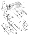
- the manually powered pool cover system includes a flexible floating pool cover 10, attached for winding around a cylindrical cover drum 12 supported for rotation between a pair of bearing block 24 at one end of a swimming pol 9.
- Figure 1b illustrates a manual safety cover with fasteners around its perimeter.
- Figure 1c shows a pool cover 11 with a rigid leading edge 15 secured to and supporting the front edge of the cover above the surface of the pool 9. Beaded tapes 23 sewn to the side edges of the pool cover 11 are captured and slide within "C" channels (not shown) of conventional swimming pool tracks 19 secured along either side of the pool.
- the pool cover 11 is extended across the pool using cables attached to the leading edge 15 or front corners 16 of the cover 11.
- an overrunning, one way clutch mechanism 28 is secured at the end of a long handle 29 three to five feet in length.
- the overrunning, one way clutch mechanism 28 is sized to journal around and engage a drive shaft 26 extending from and coupled to the cover drum 12.
- the distal end 36 of the long handle 29 is shaped for insertion into a cylindrical fitting or socket 37 welded to the exterior of a turning housing 39 containing an overrunning, one way clutch 28 journaled around and engaging the shaft 26.
- the cover drum 12 may also be rotated by a conventional crank handle 25 turning a similar drive shaft 26 extending from the opposite end of the cover drum.
- a pool owner manually slides the overrunning clutch mechanism 28 secured at the end of the long handle 39 onto the shaft 26 and pivots the handle 29 in a power stroke turning clutch 28 in a direction for engaging and rotating the shaft 26 to wind the cover 11 around the cover drum 12. The owner then pivots the handle 29 back in a return stroke in the opposite direction turning clutch 28 in the overrunning or freewheeling direction disengaged from the particular shaft 26.
- the pool owner inserts the shaped distal end 36 of the handle into the cylindrical fitting or socket 37 of the turning housing 39 and reciprocates the handle 29 back and forth in a power and a return stroke for winding the pool cover. There should be sufficient friction or other resistance to preclude unwinding rotation of the cover drum 12 being wound during the return stroke of the handle 29.
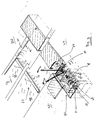
- the manually powered pool cover drive includes a flexible pool cover 11, attached for winding around a cylindrical cover drum 12 supported for rotation between a pair of bearing blocks 24 at one end of a swimming pool 9.
- the front edge 13 of the cover 11 is supported by an essentially rigid leading edge 15 spanning the width of the pool above water level by a pair of sliders 16, each sliding within a "C" channel of a conventional extruded aluminum swimming pool track 19 secured along each side of the swimming pool 9.
- Cables 21, typically a Dacron line, are incorporated into and form a beaded tape 22 sewn to the side edges of the cover 11.
- the cables 21 extend from the front corners of the cover 11, and are trained around pulleys 23 at the distal ends of the tracks 19, and return within the parallel return channels within the track 19 to ultimately connect through a system of pulleys 17 for and winding onto a cable take-up reel 18 also supported for rotation between a pair of bearing blocks 24 at the cover drum end of the pool 9.
- the beaded tapes 22 sewn to the side edges of the cover 11 are captured and slide within the "C" channels (not shown) of the tracks 19.
- the cover drum 12 and cable take-up reel 18 include shafts 26 and 27 respectively having the same diameter extending outward from an adjacent bearing block 24.
- the shaft 26 is integral with or operatively couples to rotate the cover drum 12, and shaft 27 is integral with or operatively couples to rotate the cable reel 18.
- the distal end 36 of the long handle 29 is shaped for insertion into a cylindrical fitting or socket 37 welded to the exterior of a turning housing 39 containing an overrunning, one way clutch mechanism 28. ⁇ See also Figures 5b-5d].
- an overrunning clutch mechanism 28 sized to overrun around and engage the respective extending shafts 26 or 27 is mounted at the end of a long handle 29 three to five feet in length.
- a passive one-way brake unit 31 is journaled around the shaft 27 extending from the cable reel 18 and secured to the adjacent bearing block 24 for restraining unwinding rotation of the cable reel 18, thereby preventing cable snarling due to angular momentum over spinning the cable reel 18.
- a conventional braking system such as that described in U.S. Patent No. 4,858,253 to Lamb and others would accomplish the same result, namely keep the cable reel from backlashing, it brakes in the winding direction, increasing torque required to extend the cover ⁇ .
- a pool owner manually either slides the overrunning clutch mechanism 28 secured at the end of the long handle 29 onto either the shaft 26 or 27 or inserts the socket end 36 of the handle into the turning socket 37 of the turning housing 39 and reciprocates the hand 29 back and forth in a power and return stroke for winding either the cables 21 or the pool cover 11.
- the passive one way braking unit 31 is adjusted to provide sufficient friction to preclude elastic unwinding rotation of the cable reel 18 when being wound during the return stroke of the handle 29.
- the friction resistance of the beaded tape edges 22 of the cover 11 sliding within the "C" channels of the swimming pool tracks 19 should be sufficient to offset elastic unwinding rotation of the cover drum 12 during the return stroke.
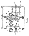
- the pool cover drive 10 is located in a cable reel & cover drum bay 32 at one end of a pool 9 below the pool deck 33.
- swimming pool tracks 19 are preferably located and secured to the underside of a coping 33 overhanging the surface of the pool water 34 on opposite side of the pool 9.
- the drive shaft 26 is coupled for rotating the cover drum 12 and drive shaft 27 is coupled for rotating the cable reel 18.
- a pair of turning housings 39a-b & 39c-d each containing one or more overrunning, one way clutch mechanisms 28 are permanently journaled around each drive shaft 26 & 27.
- a pair of long handles 29 each having a socket end 36 shaped for insertion into a cylindrical fitting or socket 37 secured to the exterior of the turning housings 39.
- the pool owner inserts the socket ends 36 of a pair of long handles 29 into the sockets 37 of either the pair of turning housings 39a-b or the pair 39c-d journaled around the respective drive shafts 26 or 27.
- Both the overrunning, one way clutches 28 of each pair of turning housing 39a-b or 39c-d are oriented to engage and overrun in the same direction.
- the pool owner simply slides or engages the clutches 28 at the ends of the two handles 29 on the particular drive shaft 26 or 27 for winding the cover 11 or the cable reel and cables 21.
- the cover 11 and cables should both respectively attach to the cover drum 12 and cable reel 18 to wind up in the same direction preferable that which allows a pool owner, standing at the end, facing the pool 9, to alternately pull one handle 29 in power strokes engaging the shaft 26 or 27 for winding, while simultaneously pushing the other handle 29 oppositely in a freewheeling return stroke rotating the clutch 28 on the shaft 26 or 27 in the overrunning direction.
- the left overrunning clutch mechanism 28 engages and rotates the particular drive shaft 26 or 27 as the right overrunning clutch mechanism 28 disengages and rotates oppositely relative to the shaft, and visa versa.
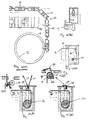
- FIGS. 4a to 4f illustrate the application of the invented manual drive to the European buoyant slat floating cover systems.
- Fig. 4a illustrates the typical slat foam filled buoyant membrane members 41 making up a pool cover 42 which extends across the pool 9 responsive to buoyancy forces of where the cover drum 12 is appropriately located beneath the pool surface.
- Figure 4b illustrates a gravity feed alternative of a buoyant slat cover system where the cover drum 12 is located above the pool 9.
- Figures 4e & 4f illustrates the insertion of a locking short bar 43 in one of the sockets 37 on one of a pair of turning housings 39 enclosing an overrunning, one way clutch mechanism 28 to prevent the cover from passively unwinding and returning to the closed position responsive to buoyant or gravity forces.
- Figure 4g schematically illustrates a conventional engageable friction brake mechanism 44 enabling an operator to temporarily brake the drum rotation while disengaging the hand(s) 29 from the socket(s) 37 of the turning housing(s) 39 of the invented drive.
- the brake mechanism 44 can also be used to prevent the cover drum 12 from unwinding during the return stroke of a single handle winding drive system.
- overrunning clutches 29 can be secured or fitted at the ends of an associated long handle or lever 29.
- the combination comprises a housing 39 welded at the end of a steel bar or black iron pipe handle 29.
- the housing 39 is bored perpendicularly with respect to handle 29 to secure or function as an exterior cylindrical raceway of a conventional overrunning clutch mechanism 28 such as a Sprag Clutch Mechanism manufactured by Carlyle Johnson Machine Company located in Manchester, Connecticut (See Fig. 6a-c) or a Torrington Type Drawn Cup Roller Clutch assembly available from The Torrington Company. (See Fig. 7a-e).
- the handle or lever 29 is a long handled ratchet socket wrench where the turning housing 39 and the associated overrunning, one way clutch mechanism 28 secured at its distal end is a socket adapted to journal around, engage and turn a drive shaft 26 or 27.
- the careful designer should consider and appreciate the magnitude of the loads or forces including torques that can be imparted/transmitted to the respective components of the overrunning clutch by the long lever arm 29.
- the mechanical advantage of a 4 foot lever arm 29 turning a 6 inch diameter cover drum or cable reel is 24:1.
- the inner and outer engagement raceways of the overrunning clutch mechanisms 28 be composed of hardened steel or other materials of comparable properties.
- the sprags or rollers of such clutch mechanisms should be composed of ball bearing steel.
- the engagement surfaces on the drive shafts 26 and 27 respectively coupled for rotating the cover drum 12 and cable reel 18 should also be composed of hardened steel materials.
- the handle 29 is a simple structural lever with a hand grip 30 at one end while the distal end 36 is shaped for insertion into the handle socket 37 of the turning housing 39.
- the careful designer should consider and appreciate the magnitude of the load or forces including torques that are to be imparted/transmitted to the turning housings 39.
- each turning housing 39 includes a handle socket 37 for receiving the distal or socket end of the long handle/lever 29.
- Two turning housings 39a & 38b and associated overrunning clutch mechanisms 28 are permanently journaled around the drive shaft 26 coupled for rotating the cover drum 12, and two housings 39c & 39d and associated overrunning clutch mechanisms 27 are permanently journaled around the drive shaft 27 coupled for rotating the cable reel 18.
- the turning housings 39a-d can be biased to maintain a particular orientation on the particular shafts 26 and 27, preferably slightly off vertical towards an operator standing above the cover drum & cable reel bay 22 inserting the distal end of the handle into the socket 37.
- gravity can be passively utilized to maintain a desired orientation by designing the entire assembly (turning housings 39, clutches 28 and associated handle sockets 37) with an off axis centers of mass such that gravity and angular momentum assures a desired (vertical) orientation of the sockets 37 in a plane perpendicular to the axis of the particular drive shaft 26/27 (Fig. 5b. 5c). Then, as illustrated in Fig.
- the sockets 27 of each pair of turning housings 39 are preferably inclined or tilted at a slight angle with respect to each other in a plane parallel to the particular drive shaft 26/27 such that the inserted handles 29 diverge to provide a comfortable separation between the pair of handles at the point where the handles are manually gripped for reciprocation back and forth in a power and a return stroke.
- the careful designer should recognize that inclining of the sockets 37 in the manner described above eliminates torque tending to twist the handles 29 in the sockets 37. [Such twisting torque would be present if the handles 39 were bent in an offset to provide lateral separation between the extending handles at the grips 30.
- the socket ends 36 of the handles 29 and the sockets 37 would have to include cooperating lands to prevent twisting rotation of the handles 29 in the sockets 37.
- This twisting torque would also axially load the overrunning, one way clutches 28 requiring a more expensive clutch bearing combination to counteract such handle torque.
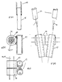
- FIGs 6a-c illustrate the elements and operational principals of a conventional sprag type overrunning clutch 50.
- Sprag overrunning clutches 50 typically incudes a sprag cage 51 for maintaining orientation of a plurality of sprags 52 concentricity between an outer cylindrical engagement raceway 53 and an inner cylindrical engagement raceway 54.
- the inner engagement raceway typically comprises the surface of a shaft 56, e.g., in the invented manual pool cover drive, the drive shafts 26 or 27.
- relative rotation between the respective inner and outer raceways 53 & 54 in one direction rotates the sprags 52 into wedging engagement between the respective raceways coupling the rotation of the raceway to the other raceway.
- Such sprag type overrunning clutch mechanisms may also include ball and or needle bearings confined by the sprag cage 51 to facilitate overrunning rotation of the respective raceways 53 & 54.
- a Torrington type roller clutch 60 transmits torque between a shaft 61 and a housing 62 in one direction and allows free overrun in the opposite direction.
- the elements of such clutch mechanics 60 include cylindrical roller or needle bearings 63 typically received within a bearing cage 64 and constrained to rotate between an exterior cylindrical raceway 65 presenting precisely formed interior ramp surfaces 66 and a cylindrical surface of a shaft 61.
- the raceway 65 is press fit into the housing 62.
- the needle bearings 63 roll freely when the shaft 62 and housing 2 are relatively rotated oppositely as indicated by the arrows in Figures 7a & 7b.
- more than one of these clutches may be press fit into a housing in order to increase the torque capacity.
- Figures 8a-b illustrate the elements and the operational principles of a conventional overrunning crank 70 where a ball 71 is biased with a spring 72 to wedge between the inner surface of a cylindrical race 73 and the exterior surface of an oblong or lobed shaft 74. When wedged, the ball 71 couples rotation of the race 73 and the lobed shaft 74. (Fig 8a). However, when race 73 rotates with respect to the lobed shaft in the other direction the ball 71 is pushed out of engagement and the race 73 and shaft 74 freewheel with respect to one another.
- Fig. 9 illustrates the elements and the operational principles of a conventional ratchet 80 where the shaft 81 includes a saw-tooth exterior surface 82, and the outer housing 83 includes one or more pivoting dogs 84 oriented and biased by a spring 86 to engage the toothed surface 82 for coupling rotation of the housing 83 to the shaft 81 in one direction while allowing the shaft 81 and housing to rotate with respect to each other in the opposite direction.
- ratcheting overrunning clutches typically used in ratchet socket wrenches and the like
- engagement is not instantaneous in the locking direction and therefore the efficiency is not as good as say the Torrington roller ramp clutches which engage almost instantaneously.
- Figure 10 illustrates the elements and operational principles of a simple passive, one-way, braking mechanism 100 utilizing conventional overrunning clutch mechanisms.
- a split cylindrical compression friction bushing 104 is provided by two braking blocks 102a-b, each having a concave semi-cylindrical bushing surface 103 positioned for defining a cylindrical bushing sized sandwiching the exterior raceway 106 of a conventional overrunning, one way clutch mechanism 107, preferably a Torrington Type Roller Clutch assembly available from The Torrington Company, a division of Ingersol Rand.
- Braking block 102a is bolted to a bearing ram 24 supporting a rotating (drive) shaft 26/27 while braking block 102b is fastened to block 102a by a pair of conventional bolts 108. Accordingly, the braking housing 100 is held stationary and the degree of friction resisting rotation of the exterior raceway or housing 106 of the overrunning clutch mechanism 107 rotating within the split cylindrical compression bushing 104 can be adjusted using the conventional bolts 108.
- the overrunning, one way clutch mechanics 107 is journaled around a shaft 26/27 to allow the shaft to freewheel when rotating in the winding direction and to engage, coupling shaft rotation to the exterior raceway or housing 106 when rotating in an unwinding direction.
- the astute mechanical designer should recognize that the described passive one-way braking mechanism 100 will not only prevent backlash caused by angular momentum overspinning the cable reel or sheet drum from which a cable or sheet is being unwound, but also will prevent unwinding rotation of a cable reel or sheet drum around which a cable or sheet is being wound induced by elastic recoil of the cable or sheet material which stretches as it is being wound.
- a momentum flywheel can be coupled to rotate with a particular drive shaft for, or reel or drum to supply such inertia.
- a momentum flywheel 35 can be coupled to rotate with the cover drum 12 and drive shaft 26 and with the cable reel 18 and drive shaft 27.
- a simple gear or sprocket and chain transmission system 112 which includes a hexahedral bearing frame 113 supporting one end of a cover drum shaft 114 extending from and turning with a cover drum 12 and cable reel shaft 115 extending from and turning with a cable reel 18.
- Gear or chain sprockets 116 are coupled to the respective shafts 114 and 115 within the bearing frame 113. Also, while shaft 114 turning with the cover drum 12 is preferentially just an axial extension of the cover drum, it is not necessary to orient the cable reels 18 and associated shaft 115 along the same axial line.
- the careful designer should realize that the turning housings 39a-d and associated sockets 37 coupling to the handles 29 will rotate with the drive shafts 26 & 27 when the particular shaft rotates in the unwinding direction. Accordingly, the hexahedral frame which supports the respective drive shafts and shafts for rotation should allow sufficient space between shafts, axles and walls to accommodate the rotating turning housings 39a-d and sockets 37.
- one way clutch 28 engage and rotate with the drive shaft when rotated in the unwinding direction provides a means for locking the cover in a closed or open position by inserting a short locking bar (Figs. 43 & 4f) into the coupling socket 37 of one turning housings 39 winding the cable reel 18 or cover drum respectively.
- the locking bar need only have sufficient length to prevent the particular turning housing 39 from rotating in the hexahedral bearing frame.
- the invented manually powered pool cover drive has been described in context of both representative and preferred embodiments which have reference to automatic swimming pool cover systems invented and developed by the applicant and others. It should be recognized that skilled engineers and designers can specify different mechanical components for manually powered pool cover drives which perform substantially the same function, in substantially the same way to achieve substantially the same result as those components described and specified above for the invented manually powered pool cover drive. For example, there are many different types of overrunning, one way clutch mechanisms which couple relative rotation of two concentric elements in one rotational direction yet allow the elements to freewheel or overrun for relative rotation in the opposite rotational direction. Accordingly, while mechanical components suitable for incorporation into the invented manually powered pool cover drive are not exactly described herein, they will fall within the scope of the invention as described and set forth in the appended claims.
Landscapes
- Engineering & Computer Science (AREA)
- Architecture (AREA)
- Civil Engineering (AREA)
- Structural Engineering (AREA)
- Storing, Repeated Paying-Out, And Re-Storing Of Elongated Articles (AREA)
- Medicinal Preparation (AREA)
- Toys (AREA)
- Percussion Or Vibration Massage (AREA)
Claims (25)
- Manueller Abdeckungsantrieb zum Wickeln einer Schwimmbeckenabdeckung (10) um eine Abdeckungstrommel (12), um eine ausgefahrene Abdeckung einzufahren, der in Kombination umfaßt:wobei eine Hin- und Herbewegung eines Griffs, der mit einem um die Antriebswelle freilaufenden und mit ihr in Eingriff gelangenden Freilauf-Einwegkupplungsmechanismus verbunden ist, in Vorwärts- und Rückwärtsrichtung in einem Arbeits- bzw. Rückkehrhub in Reaktion auf die Bewegung menschlicher Gliedmaßen die Abdeckungstrommel dreht, wodurch die Abdeckung um die Abdeckungstrommel gewickelt wird und die ausgefahrene Abdeckung eingefahren wird.i) eine Abdeckungstrommel (12),ii) eine Antriebswelle (20), die so verbunden ist, daß sie die Abdeckungstrommel in einer Wicklungsrichtung dreht, um die Abdeckung um die Abdeckungstrommel zu wickeln,
dadurch gekennzeichnet, daß er ferner umfaßt:iii) wenigstens einen Griffhebel (29),iv) wenigstens einen Freilauf-Einwegkupplungsmechanismus (28), der um die Antriebswelle freiläuft, um mit ihr in Eingriff zu gelangen, wenn sie in Wicklungsrichtung gedreht wird,v) Mittel (37, 39) zum lösbaren Verbinden des wenigstens einen Freilauf-Einwegkupplungsmechanismus mit einem Ende des wenigstens einen Griffhebels, - Manueller Abdeckungsantrieb zum Wickeln einer Schwimmbeckenabdeckung (10) um eine Abdeckungstrommel (12), um eine ausgefahrene Abdeckung einzufahren, der in Kombination umfaßt:wobei das Gleiten des am entfernten Ende des wenigstens einen Griffhebels angebrachten Freilauf-Einwegkupplungsmechanismus auf die Antriebswelle und die Hin- und Herbewegung des Griffhebels in Rückwärts- und Vorwärtsrichtung in einem Arbeits- bzw. einem Rückkehrhub in Reaktion auf die Bewegung menschlicher Gliedmaßen die Abdeckungstrommel dreht, wodurch die Abdeckung um die Abdeckungstrommel gewickelt wird und die ausgefahrene Abdeckung eingefahren wird.i) eine Abdeckungstrommel (12),ii) eine Antriebswelle (26), die so verbunden ist, daß sie die Abdeckungstrommel (12) in einer Wicklungsrichtung dreht, um die Abdeckung um die Abdeckungstrommel zu wickeln,
dadurch gekennzeichnet, daß er ferner umfaßt:iii) wenigstens einen Griffhebel (29),iv) einen Freilauf-Einwegkupplungsmechanismus (28), der am entfernten Ende des wenigstens einen Griffhebels angebracht und so bemessen ist, daß er auf die Antriebswelle gleitet, um diese freiläuft und mit ihr in Eingriff gelangt, - Manueller Abdeckungsantrieb zum Ausfahren einer Schwimmbeckenabdeckung (10) in ihre Abdeckungsposition durch Wickeln von mit vorderen Ecken der Abdeckung verbundenen Seilen um eine Seiltrommel, der in Kombination umfaßt:wobei die Hin- und Herbewegung des Griffs, der mit dem Freilauf-Einwegkupplungsmechanismus verbunden ist, der um die Antriebswelle freiläuft und mit dieser in Eingriff gelangt, in Rückwärts- und Vorwärtsrichtung in einem Arbeits- bzw. einem Rückkehrhub in Reaktion auf die Bewegung menschlicher Gliedmaßen die Seiltrommel dreht, wodurch die Seile um die Seiltrommel gewickelt werden, wodurch die Abdeckung ausgefahren wird.i) eine Schwimmbeckenabdeckung (10),ii) eine Seiltrommel (18),iii) eine Antriebswelle (20), die so verbunden ist, daß sie die Seiltrommel in einer Wicklungsrichtung dreht, um das Seil um die Seiltrommel zu wickeln,
dadurch gekennzeichnet, daß er ferner umfaßt:iv) wenigstens einen Griffhebel (29),v) wenigstens einen Freilauf-Einwegkupplungsmechanismus (28), der um die Antriebswelle freiläuft und mit dieser in Eingriff gelangt und so orientiert ist, daß er mit der Antriebswelle in Eingriff gelangt, wenn diese in eine Wicklungsrichtung gedreht wird,vi) Mittel, die den wenigstens einen Freilauf-Einwegkupplungsmechanismus (28) lösbar mit einem Ende eines langen Griffhebels verbinden, - Manueller Abdeckungsantrieb zum Ausfahren einer Schwimmbeckenabdeckung (10) in ihre Abdeckungsposition durch Wickeln von mit vorderen Ecken der Abdeckung verbundenen Seilen um eine Seiltrommel (12), der in Kombination umfaßt:i) eine Schwimmbeckenabdeckung (10),ii) eine Seiltrommel (18),iii) eine Antriebswelle (20), die so verbunden ist, daß sie die Seiltrommel in einer Wicklungsrichtung dreht, um das Seil um die Seiltrommel zu wickeln,
dadurch gekennzeichnet, daß er ferner umfaßt:iv) wenigstens einen Griffhebel (29),v) einen Freilauf-Einwegkupplungsmechanismus (28), der am entfernten Ende des Griffhebels angebracht und so bemessen ist, daß er auf die Antriebswelle gleitet, um diese freiläuft und mit ihr in Eingriff gelangt, wobei das Gleiten des am entfernten Ende des Griffhebels angebrachten Freilauf-Einwegkupplungsmechanismus um die Antriebswelle und die Hin- und Herbewegung des Griffhebels in Rückwärts- und Vorwärtsrichtung in einem Arbeits- bzw. Rückkehrhub in Reaktion auf die Bewegung menschlicher Gliedmaßen die Seiltrommel dreht, wodurch die Seile um die Seiltrommel gewickelt werden und die Abdeckung ausgefahren wird. - Manueller Abdeckungsantrieb nach Anspruch 1 oder 2, der ferner umfaßt:wobei die Abdeckungstrommel in der in der Beckenstruktur enthaltenen Flüssigkeit untergetaucht und drehbar unterstützt ist und wobei die Abdeckung schwimmfähig ist, undi) eine Beckenstruktur,ii) eine Flüssigkeit, die in der Beckenstruktur enthalten ist, undiii) lösbare Verriegelungsmittel, die eine Abwicklungsdrehung der Abdeckungstrommel verhindern,
wobei bei einem Lösen der Verriegelungsmittel die Abdeckung sich in Reaktion auf die passive Schwimmfähigkeit der Abdeckung von der Abdeckungstrommel abwickelt und ausfährt, wodurch sie die Beckenstruktur abdeckt und dabei auf der Flüssigkeit schwimmt. - Manueller Abdeckungsantrieb nach Anspruch 1 oder 2, der ferner umfaßt:wobei die Abwicklungstrommel über der Flüssigkeit über der Beckenstruktur drehbar unterstützt ist undi) eine Beckenstruktur,ii) eine Flüssigkeit, die in der Beckenstruktur enthalten ist, undiii) lösbare Verriegelungsmittel, die eine Abwicklungsdrehung der Abdeckungstrommel verhindern,
wobei die Abdeckung schwimmfähig ist,
wobei sich die Abdeckung bei einem Lösen der Verriegelungsmittel aufgrund der Schwerkraft um die Abdeckungstrommel abwickelt und ausfährt und dabei die Beckenstruktur abdeckt, wobei sie auf der Flüssigkeit schwimmt. - Manueller Abdeckungsantrieb nach Anspruch 5 oder 6, bei dem die Abdeckung mehrere flexible, miteinander verbundene, parallele, schwimmfähige Stabelemente umfaßt, die im wesentlichen parallel zu der Abdeckungstrommel orientiert sind.
- Manueller Abdeckungsantrieb nach Anspruch 7, bei dem die lösbaren Verbindungsmittel normalerweise eingerückte Friktionsbremsmittel sind.
- Manueller Abdeckungsantrieb nach Anspruch 7, bei dem die lösbaren Verriegelungsmittel in Kombination umfassen:i) einen Freilauf-Einwegkuppiungsmechanismus, der eine innere Laufbahn, die um die Antriebswelle freiläuft, und eine äußere Laufbahn besitzt, die so orientiert ist, daß sie freiläuft, wenn sich die Antriebswelle in einer Wicklungsrichtung dreht, und mit der Antriebswelle in Eingriff gelangt und sich mit dieser dreht, wenn sich die Antriebswelle in der Abwicklungsrichtung dreht,ii) ein unbewegliches Gehäuse mit Friktionsbuchsenoberflächen, die normalerweise mit der äußeren Laufbahn des Freilauf-Einwegkupplungsmechanismus in Eingriff sind, um die Drehung der äußeren Laufbahn zu verhindern, undiii) Mittel, die den Eingriff der Friktionsbuchsenoberflächen mit der äußeren Laufbahn des Freilauf-Einwegkupplungsmechanismus lösen und ihm erlauben, sich mit der Antriebswelle zu drehen.
- Manueller Abdeckungsantrieb nach Anspruch 7, bei dem die lösbaren Verriegelungsmittel in Kombination umfassen:i) ein Paar Freilauf-Einwegkupplungsmechanismen, wobei einer der Freilauf-Einwegkupplungsmechanismen, der um die Antriebswelle freiläuft und mit ihr in Eingriff gelangt, so orientiert ist, daß er mit der Antriebswelle in Eingriff gelangt, wenn sie sich in einer Wicklungsrichtung dreht,ii) eine Verriegelungsstange, die eine bestimmte Länge besitzt und so beschaffen ist, daß sie mit den Mitteln zum lösbaren Verbinden des besonderen Freilauf-Einwegkuppiungsmechanismus mit einem Ende eines Griffs verbunden werden kann,iii) eine stationäre Anschlagstruktur, die sich in der Nähe des besonderen Freilauf-Einwegkupplungsmechanismus befindet, um die Verriegelungsstange einzufangen und eine Drehung dieses besonderen Freilauf-Einwegkupplungsmechanismus zu verhindern.
- Manueller Abdeckungsantrieb nach Anspruch 1 oder 2, der ferner einen Strukturausleger enthält, der eine Beckenstruktur überspannt und eine Vorderkante der Abdeckung über einer Oberfläche einer in der Beckenstruktur enthaltenen Flüssigkeit einfängt und unterstützt.
- Manueller Abdeckungsantrieb nach Anspruch 11, bei dem die Abdeckung längs jeder Seite der Abdeckung eine Wulstkante besitzt, die in einem "C"-Kanal einer Beckenabdeckungsschiene, die längs Seitenkanten der Beckenstruktur angebracht ist, eingefangen wird und gleitet.
- Manueller Abdeckungsantrieb nach Anspruch 12, der ferner Seile enthält, die an Abschnitten der Abdeckung an den Enden des Strukturauslegers befestigt sind und in der Nähe dieser Abschnitte verlaufen, wobei eine Bedienungsperson manuell an den Seilen ziehen kann, um die Abdeckung von der Abdeckungstrommel abzuwickeln, um dadurch die Abdeckung über die Beckenstruktur auszufahren.
- Manueller Abdeckungsantrieb nach Anspruch 13, bei dem die Seile so orientiert sind, daß sie mit der Seiltrommel verbunden sind, auf diese aufgewickelt und von dieser abgewickelt werden, wobei der Antrieb ferner ein Paar Freilauf-Einwegkupplungsmechanismen undwobei wenigstens einer der Freilauf-Einwegkupplungsmechanismen so beschaffen ist, daß er um die Seiltrommel-Antriebswelle freiläuft und mit dieser in Eingriff gelangt, wobei dieser besondere Freilauf-Einwegkupplungsmechanismus so orientiert ist, daß er mit der Seiltrommel-Antriebswelle in Eingriff gelangt, wenn sie in der Wicklungsrichtung gedreht wird, wobei die Hin- und Herbewegung eines Griffs, der mit dem besonderen Freilauf-Einwegkupplungsmechanismus verbunden ist, der um die Seiltrommel-Antriebswelle freiläuft und mit dieser in Eingriff gelangt, in Rückwärts- und Vorwärtsrichtung in einem Arbeits- bzw. Rückkehrhub in Reaktion auf die Bewegung menschlicher Gliedmaßen die Seiltrommel dreht, um die Seile um die Seiltrommel zu wickeln, wodurch die Abdeckung über die Beckenstruktur ausgefahren wird.i) eine Seiltrommel-Antriebswelle enthält, die so gekoppelt ist, daß sie die Seiltrommel in einer Wicklungsrichtung dreht, um die Seile um die Seiltrommel zu wickeln, und
- Manueller Abdecküngsantrieb nach Anspruch 14, der ferner stationäre, passive Bremsmittel enthält, die ein zu schnelles Drehen in Abwicklungsrichtung der Seiltrommel abbremsen.
- Manueller Abdeckungsantrieb nach Anspruch 15, bei dem die stationären, passiven Bremsmittel in Kombination umfassen:i) einen Frellauf-Einwegkupplungsmechanismus, der eine innere Laufbahn, die um die Seiltrommel-Antriebswelle freiläuft, und eine äußere Laufbahn besitzt, die so orientiert ist, daß sie freiläuft, wenn sich die Seiltrommel-Antriebswelle in einer Wicklungsrichtung dreht, und mit der Seiltrommel-Antriebswelle in Eingriff gelangt und sich mit dieser dreht, wenn sich die Antriebswelle in der Abwicklungsrichtung dreht,ii) ein stationäres Gehäuse mit Friktionsbuchsenoberflächen, die normalerweise mit der äußeren Laufbahn des Freilauf-Einwegkupplungsmechanismus in Eingriff sind, um eine Drehung der äußeren Laufbahn zu verhindern, undiii) Mittel, die die Eingriffkraft der Friktionsbuchsenoberflächen gegen die äußere Laufbahn des Freilauf-Einwegkupplungsmechanismus einstellen.
- Manueller Abdeckungsantrieb nach Anspruch 16, bei dem:i) ein Paar Freilauf-Einwegkupplungsmechanismen so beschaffen ist, daß sie um die Abdeckungstrommel-Antriebswelle gelagert sind und um diese freilaufen, wobei jeder von ihnen so orientiert ist, daß er mit der Abdeckungstrommel-Antriebswelle in Eingriff gelangt und sich mit dieser dreht, wenn sich diese in einer Richtung dreht, in der die Abdeckung um die Abdeckungstrommel gewickelt wird, undii) ein Paar Freilauf-Einwegkupplungsmechanismen so beschaffen ist, daß sie um die Seiltrommel-Antriebswelle gelagert sind und um diese freilaufen, wobei jeder von ihnen mit der Seiltrommel-Antriebswelle in Eingriff gelangt und sich mit dieser dreht, wenn sich diese in eine Richtung dreht, in der die Seile um die Seittrommel gewickelt werden.
- Manueller Abdeckungsantrieb nach Anspruch 1 oder 3, bei dem jeder Freilauf-Einwegkupplungsmechanismus eine äußere Laufbahn besitzt und bei dem die Mittel zum lösbaren Verbinden jedes Freilauf-Einwegkupplungsmechanismus mit einem Ende jedes Griffs in Kombination umfassen:i) ein Drehgehäuse, das die äußere Laufbahn jedes Freilauf-Einwegkupplungsmechanismus umschließt und festhält, undii) eine Hülse, die einteilig mit dem Drehgehäuse ausgebildet und so geformt ist, daß sie ein entferntes Ende eines Griffs aufnimmt.
- Manuell betätigtes Beckenabdeckungssystem nach Anspruch 18, bei dem das Drehgehäuse, die Hülse und der zugeordnete Freilauf-Einwegkupplungsmechanismus einen Schwerpunkt besitzen, derart, daß die Hülse passiv orientiert wird, wenn sie um die besondere Antriebswelle gelagert ist und um diese freiläuft, um das entfernte Ende eines Griffs aufzunehmen.
- Manueller Abdeckungsantrieb nach Anspruch 19, bei dem jeder Griff eine Längsachse besitzt und jede Hülse eine Achse besitzt, wobei die Längsachse des Griffs koaxial zu der Achse der Hülse orientiert ist, wenn das entfernte Ende des Griffs in die Hülse eingesetzt und von dieser aufgenommen ist, und
wobei der Schwerpunkt des Drehgehäuses, der Hülse und des zugeordneten Freilauf-Einwegkupplungsmechanismus die Achse der Hülse passiv in einer im allgemeinen vertikalen Richtung orientiert. - Manueller Abdeckungsantrieb nach Anspruch 18, bei dem ein Paar Freilauf-Einwegkupplungsmechanismen um die Antriebswelle gelagert sind und die Hülsen, die einteilig mit dem entsprechenden Drehgehäuse ausgebildet sind, in einer seitlichen Ebene parallel zu der Antriebswelle unter einem kleinen Winkel geneigt sind, wobei ein Paar Griffe, die sich von den jeweiligen Hülsen der Kupplungsmechanismen erstrecken, unter diesem geringen Winkel auseinanderlaufen und einen seitlichen Raum zwischen Greifabschnitten des Paars Griffe in der Umgebung ihrer entfernten Enden schaffen.
- Manueller Abdeckungsantrieb nach Anspruch 21, der ferner ein Becken-Laufdeck enthält, das in bezug auf die Beckenstruktur erhöht ist und diese umgibt, wobei sich die Antriebswelle in einem Zwischenraum unter dem Becken-Laufdeck an einem Ende der Beckenstruktur befindet und dort drehbar angebracht ist.
- Manueller Abdeckungsantrieb nach Anspruch 22, bei dem der Zwischenraum eine entnehmbare Abdeckung enthält, die sich über der besonderen Antriebswelle befindet, wobei ein Becken-Eigentümer eine besondere Abdeckung entfernen kann, höchstens ein Paar Griffe mit höchstens einem Paar Freilauf-Einwegkupplungsmechanismen, die um die besondere Antriebswelle gelagert sind, die sich unter dem Becken-Laufdeck befindet, koppeln kann, gleichzeitig das Paar Griffe in Rückwärts- und Vorwärtsrichtung manuell hin und her bewegen kann, indem er abwechselnd Arbeits- und Rückkehrhübe nach links und nach rechts ausführt, wodurch entweder eine Abdeckungstrommel zum Aufwickeln und Einfahren der Abdeckung oder eine Seiltrommel zum Aufwickeln der über die Abdeckung verlaufenden Seile gedreht wird, und die abnehmbare Abdeckung ersetzen kann, wenn sie vollständig eingefahren oder über dem Becken vollständig ausgefahren ist.
- Manueller Abdeckungsantrieb nach Anspruch 18, der ferner umfaßt:i) eine Verriegelungsstange, wovon ein Ende so geformt ist, daß es in eine Hülse eines Drehgehäuses eingesetzt werden kann, und die eine bestimmte Länge besitzt, undii) eine stationäre Anschlagstruktur, die sich in der Nähe der Antriebswelle befindet, um die Verriegelungsstange einzufangen und eine Drehung dieses besonderen Freilauf-Einwegkupplungsmechanismus zu verhindern.
- Manueller Abdeckungsantrieb nach Anspruch 1, 2, 3 oder 4, der ferner ein Impuls-Schwungrad enthält, das mit der Antriebswelle gekoppelt ist und sich mit dieser dreht, um eine ausreichende Trägheit zu schaffen, um die Drehung der Antriebswelle in Wicklungsrichtung während des Rückkehrhubs eines Griffs, der einen Freilauf-Einwegkupplungsmechanismus in einer Freilaufrichtung in bezug auf die Antriebswelle dreht, fortzusetzen.
Applications Claiming Priority (3)
| Application Number | Priority Date | Filing Date | Title |
|---|---|---|---|
| US520406 | 1995-08-29 | ||
| US08/520,406 US5799342A (en) | 1995-08-29 | 1995-08-29 | Manual cover drive for swimming pools |
| PCT/US1996/013493 WO1997008408A1 (en) | 1995-08-29 | 1996-08-21 | A manuel cover drive for swimming pools |
Publications (3)
| Publication Number | Publication Date |
|---|---|
| EP0804663A1 EP0804663A1 (de) | 1997-11-05 |
| EP0804663A4 EP0804663A4 (de) | 1998-01-14 |
| EP0804663B1 true EP0804663B1 (de) | 2003-03-26 |
Family
ID=24072461
Family Applications (1)
| Application Number | Title | Priority Date | Filing Date |
|---|---|---|---|
| EP96931400A Expired - Lifetime EP0804663B1 (de) | 1995-08-29 | 1996-08-21 | Handantrieb fur schwimmbeckenabdeckungen |
Country Status (8)
| Country | Link |
|---|---|
| US (3) | US5799342A (de) |
| EP (1) | EP0804663B1 (de) |
| AT (1) | ATE235629T1 (de) |
| AU (1) | AU7009196A (de) |
| DE (1) | DE69626959T2 (de) |
| DK (1) | DK0804663T3 (de) |
| ES (1) | ES2196173T3 (de) |
| WO (1) | WO1997008408A1 (de) |
Families Citing this family (58)
| Publication number | Priority date | Publication date | Assignee | Title |
|---|---|---|---|---|
| US5616908A (en) | 1991-09-17 | 1997-04-01 | Metrologic Instruments, Inc. | Automatic countertop laser scanner with flickering laser scanner beam for improved visibility thereof during bar code symbol reading |
| US6355180B1 (en) * | 1999-11-12 | 2002-03-12 | Joseph Valentine | Swimming pool covering, heating, and cleaning system |
| US6341565B1 (en) * | 1999-11-15 | 2002-01-29 | Noble Drilling Corporation | Pipe racking system track cover |
| DE60115537T2 (de) * | 2000-04-11 | 2006-08-17 | Harry J. Kailua Last | Schwimmbecken mit automatischer Schwimmbeckenabdeckungsanordnung und Verfahren zum Betrieb einer Schwimmbeckenabdeckung |
| US6431488B1 (en) | 2000-04-24 | 2002-08-13 | Poolsaver, Inc. | Dual drive pool cover |
| US6390680B1 (en) * | 2000-09-08 | 2002-05-21 | Harry J. Last | Extruded track construct component system with threaded radial bearing end pulley for swimming pool cover systems |
| US6618869B1 (en) * | 2001-02-06 | 2003-09-16 | Teresa Jacobs | Apparatus for placing and removing solar pool cover |
| SE523501C2 (sv) * | 2001-02-09 | 2004-04-27 | Lars-Ingvar Nordstroem | Bomaggregat i en presenningshanterande maskin |
| US7861471B2 (en) * | 2001-11-08 | 2011-01-04 | Coverstar, Llc | Track assembly with apparatus for forming deck edging for swimming pools |
| US20040123380A1 (en) * | 2002-12-13 | 2004-07-01 | Shebek Michael J. | Universal track and coping assembly for pool covers |
| US6871362B1 (en) | 2003-05-27 | 2005-03-29 | Lothar J Zell | Pool cover spool |
| US7132954B2 (en) * | 2003-07-07 | 2006-11-07 | Automatic Pool Covers, Inc. | Self monitoring pool cover system |
| US6931673B1 (en) | 2003-08-25 | 2005-08-23 | Carl J. Savage, Jr. | System and method for improving the interconnection between a pool cover and a storage reel |
| FR2859350B1 (fr) * | 2003-09-05 | 2008-05-16 | Gilbert Duhamel | Dispositif pour enrouler des baches |
| AU2004279872A1 (en) * | 2003-10-09 | 2005-04-21 | Great Stuff, Inc. | Hand crank assembly for a reel |
| FR2867498B1 (fr) | 2004-03-10 | 2006-06-02 | Financ Piscine Equipement | Mecanisme d'entrainement de bord, et appareil de couverture, notamment de piscine |
| US7805779B2 (en) * | 2004-08-11 | 2010-10-05 | Katchakid Inc. | Apparatus and methods relating to a pool net |
| US7694356B2 (en) * | 2004-09-22 | 2010-04-13 | Mike Bouiss | Storage chamber cover |
| US8225433B2 (en) * | 2004-10-05 | 2012-07-24 | Murray John Phizackerley | Apparatus for minimising entanglement and bunching of an elongate means |
| US20080141599A1 (en) * | 2006-12-15 | 2008-06-19 | Donovan Advanced Hurricane Protection Inc. | Deployment apparatus and system for flexible protective covering |
| US8870121B2 (en) * | 2007-12-07 | 2014-10-28 | The Boeing Company | Actuating device |
| BE1018228A3 (fr) * | 2008-07-25 | 2010-07-06 | Becoflex S A | Dispositif de couverture d'une surface. |
| ES2319084B1 (es) * | 2008-10-20 | 2010-03-16 | Thyssenkrupp Elevator Innovation | Junta longitudinal transversal. |
| BE1018497A3 (fr) * | 2008-11-12 | 2011-02-01 | Becoflex S A | Dispositif de couverture d'une surface. |
| US8613116B1 (en) * | 2009-01-22 | 2013-12-24 | Robyn Wood | Pool cover handling device and methods of use |
| FR2956141B1 (fr) * | 2010-02-09 | 2012-11-16 | Alsace Piscine Creation | Couverture pour bassin tel qu'une piscine ou similaire et bassin equipe d'une telle couverture |
| USD645162S1 (en) * | 2010-03-11 | 2011-09-13 | Dave Martell | Pool covering system |
| USD695909S1 (en) | 2010-03-11 | 2013-12-17 | Dave Martell | Pool covering system |
| US8683621B1 (en) * | 2010-05-26 | 2014-04-01 | Eze Llc | Roll-up spa and swim spa cover |
| BE1019762A4 (fr) | 2011-01-11 | 2012-12-04 | Becoflex S A | Dispositif de couverture d'une surface avec tambour monte sur un palier a rotule. |
| ES2368327B1 (es) | 2011-07-20 | 2012-09-18 | Thyssenkrupp Elevator Innovation Center, S.A. | Junta longitudinal. |
| US8205319B1 (en) * | 2011-11-29 | 2012-06-26 | David Dunn | Two piece corner framing element for swimming pool extrusions with pool-liner anchor channels |
| US9284741B2 (en) | 2012-06-29 | 2016-03-15 | Palladium Product Development & Design Inc. | Cover apparatus including a cover assembly and at least one drive mechanism |
| US9988837B2 (en) * | 2012-07-13 | 2018-06-05 | Hunter Douglas Industries Switzerland Gmbh | Variable force brake for a window covering operating system |
| US9217282B2 (en) * | 2012-07-13 | 2015-12-22 | Newell Window Furnishings, Inc. | Window covering and operating system |
| BE1021407B1 (fr) | 2012-10-24 | 2015-11-17 | Becoflex S.A. | Dispositif de couverture d'une surface comprenant des bourrelets de fixation le long des bords de la couverture. |
| FR3005643B1 (fr) * | 2013-05-14 | 2015-05-29 | Alcorem | Enrouleur pour bache ou structure gonflable |
| WO2014189949A1 (en) * | 2013-05-21 | 2014-11-27 | Harken, Incorporated | Fabric roller system and method |
| US8949692B1 (en) * | 2014-01-23 | 2015-02-03 | DSSD, Inc. | Method and system for service-aware parity placement in a storage system |
| US20160222722A1 (en) * | 2015-02-03 | 2016-08-04 | Newell Window Furnishings, Inc. | Window covering and operating system |
| CN105349332B (zh) * | 2015-12-15 | 2017-11-10 | 乌毡帽酒业有限公司 | 一种发酵池纱布覆盖装置 |
| US10214929B2 (en) | 2016-01-07 | 2019-02-26 | David B. Stone, JR. | Floating swimming pool cover |
| BE1023457B1 (fr) | 2016-01-25 | 2017-03-27 | Becoflex S.A. | Dispositif de couverture d'une surface comprenant des moyens d'enclenchement |
| FR3057891B1 (fr) * | 2016-10-20 | 2019-10-25 | Unicum Transmission De Puissance | Ensemble de motorisation comportant au moins un groupe motoreducteur |
| GB2556892B (en) * | 2016-11-23 | 2022-04-27 | Latchways Plc | Self-retracting lifeline fall arrest device |
| CN107486127A (zh) * | 2017-09-27 | 2017-12-19 | 泰兴汤臣压克力有限公司 | 用于亚克力板的聚合池 |
| FI127709B (fi) * | 2017-10-17 | 2018-12-31 | Rectec Eng Oy | Ripesuoja ja menetelmä ripesuojan siirtämiseksi |
| US10876309B2 (en) | 2017-11-28 | 2020-12-29 | Voice Technology Solutions, Inc. | Pool cover anchor |
| BE1026976B1 (fr) | 2018-12-19 | 2020-08-21 | Becoflex Sa | Dispositif de couverture gonflable d'une surface |
| USD956266S1 (en) | 2019-04-08 | 2022-06-28 | Palladium Product Development & Design Inc. | Tractor feed strip |
| GB2588153A (en) * | 2019-10-10 | 2021-04-21 | Green Light Packaging Ltd | Void-fill paper-packaging apparatus |
| BE1027806B1 (fr) | 2019-11-28 | 2021-06-28 | Becoflex | Dispositif de couverture d'une surface comprenant des moyens de verrouillage discrets |
| BE1028093B1 (fr) | 2020-02-26 | 2021-09-23 | Becoflex | Dispositif de couverture d'une surface comprenant des moyens de verrouillage d'une couverture dans une rainure |
| BE1029655A9 (fr) | 2021-08-03 | 2023-03-13 | Becoflex | Dispositif compact de couverture d'une surface comprenant deux essieux pour le deploiement et le retrait de la couverture |
| BE1030222B1 (fr) | 2022-01-27 | 2023-08-28 | Becoflex | Dispositif compact de couverture d'une surface comprenant un système de securite en cas de mauvais verrouillage de la couverture |
| US20240254793A1 (en) * | 2023-01-26 | 2024-08-01 | Sentry Covers, LLC | Reversible gear and spool system for pool cover assembly |
| BE1032349B1 (fr) | 2024-01-22 | 2025-08-25 | Becoflex | Dispositif de couverture d’une surface comprenant un mécanisme de translation longitudinale de tambour, muni d’un système d’embrayage |
| FR3159404A1 (fr) * | 2024-02-21 | 2025-08-22 | Airshell | Dispositif de protection d’un bassin, et procédé correspondant |
Family Cites Families (24)
| Publication number | Priority date | Publication date | Assignee | Title |
|---|---|---|---|---|
| US2754900A (en) * | 1952-09-03 | 1956-07-17 | Karobonik Jack | Safety pool cover |
| US2958083A (en) * | 1955-09-19 | 1960-11-01 | Nemoede | Swimming pool safety device |
| US3019450A (en) * | 1958-09-29 | 1962-02-06 | American Typesetting Corp | Retractable swimming pool cover |
| US3050743A (en) * | 1961-08-07 | 1962-08-28 | Philip A Mallinckrodt | Extendible and retractable cover apparatus for swimming pools |
| BE705391A (de) * | 1967-10-19 | 1968-03-01 | ||
| US3613125A (en) * | 1969-09-19 | 1971-10-19 | Mile Ivkovich | Swimming pool cover |
| US3613126A (en) * | 1969-10-22 | 1971-10-19 | Robert Granderath | Buoyant cover for a swimming pool |
| US3776517A (en) * | 1972-04-03 | 1973-12-04 | R Davis | Winch for use on sailboats |
| ES426883A1 (es) * | 1974-02-13 | 1976-09-01 | Sabe Guevre | Perfeccionamientos en cubiertas para piscinas. |
| US3982286A (en) * | 1974-10-15 | 1976-09-28 | Elton Gordon Foster | Swimming pool cover |
| US4195370A (en) * | 1978-09-12 | 1980-04-01 | Budd-Ke Enterprises, Inc. | Apparatus for reeling and unreeling pool covers |
| US4411031A (en) * | 1980-11-28 | 1983-10-25 | Stolar Pool Covers Ltd. | Buoyant swimming pool cover |
| US4470404A (en) * | 1981-02-23 | 1984-09-11 | Kremen Richard D | Apparatus for and method of heating a swimming pool |
| US4385407A (en) * | 1981-06-19 | 1983-05-31 | Zook Kenneth W | Floatable pool cover |
| US4459711A (en) * | 1982-12-13 | 1984-07-17 | Donald W. Sartain | Swimming pool cover assembly |
| IE55830B1 (en) * | 1983-11-14 | 1991-01-30 | Hess Fred | Swimming pool cover |
| DE8519059U1 (de) * | 1985-07-01 | 1990-10-25 | Krüll, Andreas, 4040 Neuss | Schwimmbadabdeckung |
| DE3700546A1 (de) * | 1986-12-17 | 1988-07-07 | Eckhard Schirmer | Abdeckvorrichtung fuer schwimmbecken od.dgl. |
| US5349707A (en) * | 1988-10-17 | 1994-09-27 | Last Harry J | Split stop for automatic swimming pool covers with a hydraulic drive system |
| US5327590A (en) * | 1988-10-17 | 1994-07-12 | Last Harry J | Automatic swimming pool cover with a dual hydraulic drive system |
| US4939798A (en) * | 1988-10-17 | 1990-07-10 | Last Harry J | Leading edge and track slider system for an automatic swimming pool cover |
| US5067184A (en) * | 1988-10-17 | 1991-11-26 | Last Harry J | Cover drum having tapered ends and automatic swimming pool cover |
| SE505612C2 (sv) * | 1994-02-22 | 1997-09-22 | Alvin C Collins | Spärrskaft innefattande ett långsträckt manöverskaft med ett handgrepp vid en ände och en verktygshållare vid en motsatt ände |
| US5425143A (en) * | 1994-07-21 | 1995-06-20 | Kalandovsky; Jiri | Multiple pool cover deployment method and apparatus |
-
1995
- 1995-08-29 US US08/520,406 patent/US5799342A/en not_active Expired - Lifetime
-
1996
- 1996-08-21 DE DE69626959T patent/DE69626959T2/de not_active Expired - Fee Related
- 1996-08-21 WO PCT/US1996/013493 patent/WO1997008408A1/en not_active Ceased
- 1996-08-21 ES ES96931400T patent/ES2196173T3/es not_active Expired - Lifetime
- 1996-08-21 DK DK96931400T patent/DK0804663T3/da active
- 1996-08-21 AU AU70091/96A patent/AU7009196A/en not_active Abandoned
- 1996-08-21 AT AT96931400T patent/ATE235629T1/de not_active IP Right Cessation
- 1996-08-21 EP EP96931400A patent/EP0804663B1/de not_active Expired - Lifetime
-
1998
- 1998-04-14 US US09/063,095 patent/US5930848A/en not_active Expired - Lifetime
-
1999
- 1999-01-25 US US09/236,421 patent/US6026522A/en not_active Expired - Lifetime
Also Published As
| Publication number | Publication date |
|---|---|
| ATE235629T1 (de) | 2003-04-15 |
| US5930848A (en) | 1999-08-03 |
| US5799342A (en) | 1998-09-01 |
| DK0804663T3 (da) | 2003-07-21 |
| WO1997008408A1 (en) | 1997-03-06 |
| DE69626959D1 (de) | 2003-04-30 |
| EP0804663A4 (de) | 1998-01-14 |
| AU7009196A (en) | 1997-03-19 |
| DE69626959T2 (de) | 2004-02-19 |
| ES2196173T3 (es) | 2003-12-16 |
| US6026522A (en) | 2000-02-22 |
| EP0804663A1 (de) | 1997-11-05 |
Similar Documents
| Publication | Publication Date | Title |
|---|---|---|
| EP0804663B1 (de) | Handantrieb fur schwimmbeckenabdeckungen | |
| US5913613A (en) | Cover operation system | |
| US20100051889A1 (en) | Personal lift device | |
| US5920922A (en) | Cover system with edge stops | |
| US6622318B2 (en) | Pool cover system with retracting and adjacent extending mechanisms operable by a portable power source | |
| KR20180043182A (ko) | 듀얼 모드 건축 구조물 덮개 | |
| US9284741B2 (en) | Cover apparatus including a cover assembly and at least one drive mechanism | |
| EP2151163A1 (de) | Zugmaschine, Traktorsystem und Sicherheitsvorrichtung | |
| US6871362B1 (en) | Pool cover spool | |
| US4858253A (en) | Mechanism for extending and retracting swimming pool covers | |
| US9353539B2 (en) | Apparatus for automatic cover assembly | |
| US3391410A (en) | Retainer and lock for swimming pool covers | |
| US4351072A (en) | Semi-automatic pool cover | |
| JPH09144323A (ja) | 仮設テントにおけるシートの開閉機構 | |
| US3707007A (en) | Pool cover arrangement | |
| US20200370319A1 (en) | Automatic cover assembly for a swmming pool | |
| CA2655992A1 (en) | Locking rope reel | |
| WO2009067667A1 (en) | Cover system with support means and snap-top decorative cap | |
| KR102118121B1 (ko) | 안전 로프 설치를 위한 권선기 | |
| KR20120055402A (ko) | 반자동 오징어 조상기 | |
| WO2005118983A1 (en) | Positive drive cover system | |
| US12270222B2 (en) | Hot tub cover hoist mechanism | |
| KR102909694B1 (ko) | 건축물지붕 제설장치 | |
| US20070256230A1 (en) | Apparatus for Minimising Entanglement and Bunching of an Elongate Means | |
| JP2517386Y2 (ja) | 網締め装置 |
Legal Events
| Date | Code | Title | Description |
|---|---|---|---|
| PUAI | Public reference made under article 153(3) epc to a published international application that has entered the european phase |
Free format text: ORIGINAL CODE: 0009012 |
|
| 17P | Request for examination filed |
Effective date: 19970904 |
|
| AK | Designated contracting states |
Kind code of ref document: A1 Designated state(s): AT BE CH DE DK ES FR GB IT LI LU NL SE |
|
| A4 | Supplementary search report drawn up and despatched |
Effective date: 19971126 |
|
| AK | Designated contracting states |
Kind code of ref document: A4 Designated state(s): AT BE CH DE DK ES FR GB IT LI LU NL SE |
|
| 17Q | First examination report despatched |
Effective date: 19990903 |
|
| GRAG | Despatch of communication of intention to grant |
Free format text: ORIGINAL CODE: EPIDOS AGRA |
|
| GRAG | Despatch of communication of intention to grant |
Free format text: ORIGINAL CODE: EPIDOS AGRA |
|
| GRAG | Despatch of communication of intention to grant |
Free format text: ORIGINAL CODE: EPIDOS AGRA |
|
| GRAH | Despatch of communication of intention to grant a patent |
Free format text: ORIGINAL CODE: EPIDOS IGRA |
|
| GRAH | Despatch of communication of intention to grant a patent |
Free format text: ORIGINAL CODE: EPIDOS IGRA |
|
| GRAA | (expected) grant |
Free format text: ORIGINAL CODE: 0009210 |
|
| AK | Designated contracting states |
Designated state(s): AT BE CH DE DK ES FR GB IT LI LU NL SE |
|
| REG | Reference to a national code |
Ref country code: GB Ref legal event code: FG4D |
|
| REG | Reference to a national code |
Ref country code: CH Ref legal event code: EP |
|
| REF | Corresponds to: |
Ref document number: 69626959 Country of ref document: DE Date of ref document: 20030430 Kind code of ref document: P |
|
| REG | Reference to a national code |
Ref country code: CH Ref legal event code: NV Representative=s name: FELBER & PARTNER AG PATENTANWAELTE |
|
| REG | Reference to a national code |
Ref country code: DK Ref legal event code: T3 |
|
| REG | Reference to a national code |
Ref country code: SE Ref legal event code: TRGR |
|
| REG | Reference to a national code |
Ref country code: ES Ref legal event code: FG2A Ref document number: 2196173 Country of ref document: ES Kind code of ref document: T3 |
|
| ET | Fr: translation filed | ||
| PLBE | No opposition filed within time limit |
Free format text: ORIGINAL CODE: 0009261 |
|
| STAA | Information on the status of an ep patent application or granted ep patent |
Free format text: STATUS: NO OPPOSITION FILED WITHIN TIME LIMIT |
|
| 26N | No opposition filed |
Effective date: 20031230 |
|
| PGFP | Annual fee paid to national office [announced via postgrant information from national office to epo] |
Ref country code: ES Payment date: 20070822 Year of fee payment: 12 |
|
| PGFP | Annual fee paid to national office [announced via postgrant information from national office to epo] |
Ref country code: LU Payment date: 20070827 Year of fee payment: 12 |
|
| PGFP | Annual fee paid to national office [announced via postgrant information from national office to epo] |
Ref country code: DK Payment date: 20070828 Year of fee payment: 12 |
|
| PGFP | Annual fee paid to national office [announced via postgrant information from national office to epo] |
Ref country code: DE Payment date: 20070904 Year of fee payment: 12 |
|
| PGFP | Annual fee paid to national office [announced via postgrant information from national office to epo] |
Ref country code: CH Payment date: 20070827 Year of fee payment: 12 Ref country code: AT Payment date: 20070822 Year of fee payment: 12 |
|
| PGFP | Annual fee paid to national office [announced via postgrant information from national office to epo] |
Ref country code: GB Payment date: 20070828 Year of fee payment: 12 |
|
| PGFP | Annual fee paid to national office [announced via postgrant information from national office to epo] |
Ref country code: SE Payment date: 20070827 Year of fee payment: 12 Ref country code: NL Payment date: 20070820 Year of fee payment: 12 Ref country code: IT Payment date: 20070828 Year of fee payment: 12 Ref country code: BE Payment date: 20070823 Year of fee payment: 12 |
|
| PGFP | Annual fee paid to national office [announced via postgrant information from national office to epo] |
Ref country code: FR Payment date: 20070821 Year of fee payment: 12 |
|
| REG | Reference to a national code |
Ref country code: DK Ref legal event code: EBP |
|
| REG | Reference to a national code |
Ref country code: CH Ref legal event code: PL |
|
| EUG | Se: european patent has lapsed | ||
| GBPC | Gb: european patent ceased through non-payment of renewal fee |
Effective date: 20080821 |
|
| PG25 | Lapsed in a contracting state [announced via postgrant information from national office to epo] |
Ref country code: AT Free format text: LAPSE BECAUSE OF NON-PAYMENT OF DUE FEES Effective date: 20080821 |
|
| NLV4 | Nl: lapsed or anulled due to non-payment of the annual fee |
Effective date: 20090301 |
|
| PG25 | Lapsed in a contracting state [announced via postgrant information from national office to epo] |
Ref country code: NL Free format text: LAPSE BECAUSE OF NON-PAYMENT OF DUE FEES Effective date: 20090301 |
|
| REG | Reference to a national code |
Ref country code: FR Ref legal event code: ST Effective date: 20090430 |
|
| PG25 | Lapsed in a contracting state [announced via postgrant information from national office to epo] |
Ref country code: LI Free format text: LAPSE BECAUSE OF NON-PAYMENT OF DUE FEES Effective date: 20080831 Ref country code: CH Free format text: LAPSE BECAUSE OF NON-PAYMENT OF DUE FEES Effective date: 20080831 |
|
| PG25 | Lapsed in a contracting state [announced via postgrant information from national office to epo] |
Ref country code: DK Free format text: LAPSE BECAUSE OF NON-PAYMENT OF DUE FEES Effective date: 20080831 Ref country code: BE Free format text: LAPSE BECAUSE OF NON-PAYMENT OF DUE FEES Effective date: 20080831 |
|
| PG25 | Lapsed in a contracting state [announced via postgrant information from national office to epo] |
Ref country code: IT Free format text: LAPSE BECAUSE OF NON-PAYMENT OF DUE FEES Effective date: 20080821 Ref country code: FR Free format text: LAPSE BECAUSE OF NON-PAYMENT OF DUE FEES Effective date: 20080901 Ref country code: DE Free format text: LAPSE BECAUSE OF NON-PAYMENT OF DUE FEES Effective date: 20090303 |
|
| REG | Reference to a national code |
Ref country code: ES Ref legal event code: FD2A Effective date: 20080822 |
|
| PG25 | Lapsed in a contracting state [announced via postgrant information from national office to epo] |
Ref country code: GB Free format text: LAPSE BECAUSE OF NON-PAYMENT OF DUE FEES Effective date: 20080821 |
|
| PG25 | Lapsed in a contracting state [announced via postgrant information from national office to epo] |
Ref country code: ES Free format text: LAPSE BECAUSE OF NON-PAYMENT OF DUE FEES Effective date: 20080822 |
|
| PG25 | Lapsed in a contracting state [announced via postgrant information from national office to epo] |
Ref country code: LU Free format text: LAPSE BECAUSE OF NON-PAYMENT OF DUE FEES Effective date: 20080821 |
|
| PG25 | Lapsed in a contracting state [announced via postgrant information from national office to epo] |
Ref country code: SE Free format text: LAPSE BECAUSE OF NON-PAYMENT OF DUE FEES Effective date: 20080822 |