EP0804640B1 - Improvements in continuous filaments, yarns, and tows - Google Patents
Improvements in continuous filaments, yarns, and tows Download PDFInfo
- Publication number
- EP0804640B1 EP0804640B1 EP95904746A EP95904746A EP0804640B1 EP 0804640 B1 EP0804640 B1 EP 0804640B1 EP 95904746 A EP95904746 A EP 95904746A EP 95904746 A EP95904746 A EP 95904746A EP 0804640 B1 EP0804640 B1 EP 0804640B1
- Authority
- EP
- European Patent Office
- Prior art keywords
- filaments
- shrinkage
- tex
- max
- polyester
- Prior art date
- Legal status (The legal status is an assumption and is not a legal conclusion. Google has not performed a legal analysis and makes no representation as to the accuracy of the status listed.)
- Expired - Lifetime
Links
- 230000006872 improvement Effects 0.000 title description 8
- 229920000728 polyester Polymers 0.000 claims description 149
- 238000000034 method Methods 0.000 claims description 145
- 230000008569 process Effects 0.000 claims description 140
- 229920000642 polymer Polymers 0.000 claims description 102
- 238000010438 heat treatment Methods 0.000 claims description 53
- 238000011282 treatment Methods 0.000 claims description 51
- 238000001816 cooling Methods 0.000 claims description 28
- 238000002425 crystallisation Methods 0.000 claims description 26
- 230000008025 crystallization Effects 0.000 claims description 26
- 238000009987 spinning Methods 0.000 claims description 25
- 238000010791 quenching Methods 0.000 claims description 24
- 238000002844 melting Methods 0.000 claims description 17
- 230000008018 melting Effects 0.000 claims description 17
- 239000004952 Polyamide Substances 0.000 claims description 16
- 229920002647 polyamide Polymers 0.000 claims description 16
- 229920002302 Nylon 6,6 Polymers 0.000 claims description 14
- 230000000171 quenching effect Effects 0.000 claims description 10
- 238000002074 melt spinning Methods 0.000 claims description 9
- 230000009477 glass transition Effects 0.000 claims description 8
- -1 poly(ethylene terephthalate) Polymers 0.000 claims description 8
- 239000011800 void material Substances 0.000 claims description 6
- 239000000155 melt Substances 0.000 claims description 5
- 230000001788 irregular Effects 0.000 claims description 4
- 238000004519 manufacturing process Methods 0.000 claims description 4
- 229920006149 polyester-amide block copolymer Polymers 0.000 claims description 4
- 230000008859 change Effects 0.000 claims description 3
- 239000000203 mixture Substances 0.000 claims description 3
- 229920000139 polyethylene terephthalate Polymers 0.000 claims description 3
- 239000005020 polyethylene terephthalate Substances 0.000 claims description 3
- 238000004581 coalescence Methods 0.000 claims description 2
- 238000011064 split stream procedure Methods 0.000 claims 3
- 229920001778 nylon Polymers 0.000 description 44
- 239000004677 Nylon Substances 0.000 description 43
- 239000004744 fabric Substances 0.000 description 34
- 239000004753 textile Substances 0.000 description 28
- 239000000975 dye Substances 0.000 description 21
- 239000000835 fiber Substances 0.000 description 17
- 230000007423 decrease Effects 0.000 description 14
- 239000013078 crystal Substances 0.000 description 12
- 229920001634 Copolyester Polymers 0.000 description 9
- 238000004043 dyeing Methods 0.000 description 9
- 238000012545 processing Methods 0.000 description 9
- 230000000052 comparative effect Effects 0.000 description 8
- 239000002131 composite material Substances 0.000 description 8
- 238000004804 winding Methods 0.000 description 8
- 238000009940 knitting Methods 0.000 description 7
- 238000009941 weaving Methods 0.000 description 7
- 230000006399 behavior Effects 0.000 description 6
- 239000006085 branching agent Substances 0.000 description 6
- 125000002091 cationic group Chemical group 0.000 description 6
- 238000010622 cold drawing Methods 0.000 description 6
- 238000002788 crimping Methods 0.000 description 6
- 230000003247 decreasing effect Effects 0.000 description 6
- 238000011161 development Methods 0.000 description 6
- 230000002829 reductive effect Effects 0.000 description 6
- 229920001577 copolymer Polymers 0.000 description 5
- 238000000113 differential scanning calorimetry Methods 0.000 description 5
- 230000000694 effects Effects 0.000 description 5
- 238000001125 extrusion Methods 0.000 description 5
- 229920001519 homopolymer Polymers 0.000 description 5
- 239000000543 intermediate Substances 0.000 description 5
- 238000012986 modification Methods 0.000 description 5
- 230000004048 modification Effects 0.000 description 5
- 230000035882 stress Effects 0.000 description 5
- GWEVSGVZZGPLCZ-UHFFFAOYSA-N Titan oxide Chemical compound O=[Ti]=O GWEVSGVZZGPLCZ-UHFFFAOYSA-N 0.000 description 4
- 238000010168 coupling process Methods 0.000 description 4
- MTHSVFCYNBDYFN-UHFFFAOYSA-N diethylene glycol Chemical compound OCCOCCO MTHSVFCYNBDYFN-UHFFFAOYSA-N 0.000 description 4
- 238000005516 engineering process Methods 0.000 description 4
- 238000011049 filling Methods 0.000 description 4
- 238000009998 heat setting Methods 0.000 description 4
- 239000002759 woven fabric Substances 0.000 description 4
- 239000002585 base Substances 0.000 description 3
- 230000008901 benefit Effects 0.000 description 3
- 230000015572 biosynthetic process Effects 0.000 description 3
- 239000000969 carrier Substances 0.000 description 3
- 238000010276 construction Methods 0.000 description 3
- 230000008878 coupling Effects 0.000 description 3
- 238000005859 coupling reaction Methods 0.000 description 3
- 239000000986 disperse dye Substances 0.000 description 3
- JFCQEDHGNNZCLN-UHFFFAOYSA-N glutaric acid Chemical compound OC(=O)CCCC(O)=O JFCQEDHGNNZCLN-UHFFFAOYSA-N 0.000 description 3
- 239000002243 precursor Substances 0.000 description 3
- 238000002360 preparation method Methods 0.000 description 3
- 238000011105 stabilization Methods 0.000 description 3
- 230000010512 thermal transition Effects 0.000 description 3
- 238000012546 transfer Methods 0.000 description 3
- 230000007704 transition Effects 0.000 description 3
- MBYLVOKEDDQJDY-UHFFFAOYSA-N tris(2-aminoethyl)amine Chemical compound NCCN(CCN)CCN MBYLVOKEDDQJDY-UHFFFAOYSA-N 0.000 description 3
- XLYOFNOQVPJJNP-UHFFFAOYSA-N water Substances O XLYOFNOQVPJJNP-UHFFFAOYSA-N 0.000 description 3
- PCTMTFRHKVHKIS-BMFZQQSSSA-N (1s,3r,4e,6e,8e,10e,12e,14e,16e,18s,19r,20r,21s,25r,27r,30r,31r,33s,35r,37s,38r)-3-[(2r,3s,4s,5s,6r)-4-amino-3,5-dihydroxy-6-methyloxan-2-yl]oxy-19,25,27,30,31,33,35,37-octahydroxy-18,20,21-trimethyl-23-oxo-22,39-dioxabicyclo[33.3.1]nonatriaconta-4,6,8,10 Chemical compound C1C=C2C[C@@H](OS(O)(=O)=O)CC[C@]2(C)[C@@H]2[C@@H]1[C@@H]1CC[C@H]([C@H](C)CCCC(C)C)[C@@]1(C)CC2.O[C@H]1[C@@H](N)[C@H](O)[C@@H](C)O[C@H]1O[C@H]1/C=C/C=C/C=C/C=C/C=C/C=C/C=C/[C@H](C)[C@@H](O)[C@@H](C)[C@H](C)OC(=O)C[C@H](O)C[C@H](O)CC[C@@H](O)[C@H](O)C[C@H](O)C[C@](O)(C[C@H](O)[C@H]2C(O)=O)O[C@H]2C1 PCTMTFRHKVHKIS-BMFZQQSSSA-N 0.000 description 2
- 101000878457 Macrocallista nimbosa FMRFamide Proteins 0.000 description 2
- 229920002292 Nylon 6 Polymers 0.000 description 2
- VYPSYNLAJGMNEJ-UHFFFAOYSA-N Silicium dioxide Chemical compound O=[Si]=O VYPSYNLAJGMNEJ-UHFFFAOYSA-N 0.000 description 2
- 239000002253 acid Substances 0.000 description 2
- 238000004458 analytical method Methods 0.000 description 2
- 239000003795 chemical substances by application Substances 0.000 description 2
- 238000009833 condensation Methods 0.000 description 2
- 230000005494 condensation Effects 0.000 description 2
- 230000003750 conditioning effect Effects 0.000 description 2
- 230000007547 defect Effects 0.000 description 2
- 230000001419 dependent effect Effects 0.000 description 2
- 238000013461 design Methods 0.000 description 2
- 230000014509 gene expression Effects 0.000 description 2
- 238000002347 injection Methods 0.000 description 2
- 239000007924 injection Substances 0.000 description 2
- QQVIHTHCMHWDBS-UHFFFAOYSA-L isophthalate(2-) Chemical compound [O-]C(=O)C1=CC=CC(C([O-])=O)=C1 QQVIHTHCMHWDBS-UHFFFAOYSA-L 0.000 description 2
- 238000009981 jet dyeing Methods 0.000 description 2
- 239000010985 leather Substances 0.000 description 2
- 230000000670 limiting effect Effects 0.000 description 2
- 238000005259 measurement Methods 0.000 description 2
- 230000036961 partial effect Effects 0.000 description 2
- 238000001953 recrystallisation Methods 0.000 description 2
- 239000007787 solid Substances 0.000 description 2
- 239000000126 substance Substances 0.000 description 2
- 238000010998 test method Methods 0.000 description 2
- DYLIWHYUXAJDOJ-OWOJBTEDSA-N (e)-4-(6-aminopurin-9-yl)but-2-en-1-ol Chemical compound NC1=NC=NC2=C1N=CN2C\C=C\CO DYLIWHYUXAJDOJ-OWOJBTEDSA-N 0.000 description 1
- YKCSYIYQRSVLAK-UHFFFAOYSA-N 3,5-dimethyl-2-phenylmorpholine Chemical compound CC1NC(C)COC1C1=CC=CC=C1 YKCSYIYQRSVLAK-UHFFFAOYSA-N 0.000 description 1
- MMINFSMURORWKH-UHFFFAOYSA-N 3,6-dioxabicyclo[6.2.2]dodeca-1(10),8,11-triene-2,7-dione Chemical group O=C1OCCOC(=O)C2=CC=C1C=C2 MMINFSMURORWKH-UHFFFAOYSA-N 0.000 description 1
- LLLVZDVNHNWSDS-UHFFFAOYSA-N 4-methylidene-3,5-dioxabicyclo[5.2.2]undeca-1(9),7,10-triene-2,6-dione Chemical compound C1(C2=CC=C(C(=O)OC(=C)O1)C=C2)=O LLLVZDVNHNWSDS-UHFFFAOYSA-N 0.000 description 1
- IJGRMHOSHXDMSA-UHFFFAOYSA-N Atomic nitrogen Chemical compound N#N IJGRMHOSHXDMSA-UHFFFAOYSA-N 0.000 description 1
- 239000004743 Polypropylene Substances 0.000 description 1
- XBDQKXXYIPTUBI-UHFFFAOYSA-M Propionate Chemical compound CCC([O-])=O XBDQKXXYIPTUBI-UHFFFAOYSA-M 0.000 description 1
- 239000000980 acid dye Substances 0.000 description 1
- 239000000654 additive Substances 0.000 description 1
- 230000000996 additive effect Effects 0.000 description 1
- 239000003513 alkali Substances 0.000 description 1
- 229910052783 alkali metal Inorganic materials 0.000 description 1
- 238000007664 blowing Methods 0.000 description 1
- 238000009835 boiling Methods 0.000 description 1
- 230000001680 brushing effect Effects 0.000 description 1
- 239000003518 caustics Substances 0.000 description 1
- 230000001143 conditioned effect Effects 0.000 description 1
- 239000002826 coolant Substances 0.000 description 1
- 230000003111 delayed effect Effects 0.000 description 1
- 229910001873 dinitrogen Inorganic materials 0.000 description 1
- 238000010036 direct spinning Methods 0.000 description 1
- 238000009826 distribution Methods 0.000 description 1
- 238000011143 downstream manufacturing Methods 0.000 description 1
- 238000007688 edging Methods 0.000 description 1
- 238000005530 etching Methods 0.000 description 1
- 238000011156 evaluation Methods 0.000 description 1
- 239000000675 fabric finishing Substances 0.000 description 1
- 238000009962 finishing (textile) Methods 0.000 description 1
- 238000007730 finishing process Methods 0.000 description 1
- 244000144992 flock Species 0.000 description 1
- 239000011521 glass Substances 0.000 description 1
- 125000003827 glycol group Chemical group 0.000 description 1
- 238000010348 incorporation Methods 0.000 description 1
- 239000004615 ingredient Substances 0.000 description 1
- 238000003780 insertion Methods 0.000 description 1
- 230000037431 insertion Effects 0.000 description 1
- 238000002955 isolation Methods 0.000 description 1
- 150000002605 large molecules Chemical class 0.000 description 1
- 239000007788 liquid Substances 0.000 description 1
- 229920002521 macromolecule Polymers 0.000 description 1
- 239000011159 matrix material Substances 0.000 description 1
- 229910044991 metal oxide Inorganic materials 0.000 description 1
- 150000004706 metal oxides Chemical class 0.000 description 1
- 239000003607 modifier Substances 0.000 description 1
- 238000012856 packing Methods 0.000 description 1
- XNGIFLGASWRNHJ-UHFFFAOYSA-N phthalic acid Chemical compound OC(=O)C1=CC=CC=C1C(O)=O XNGIFLGASWRNHJ-UHFFFAOYSA-N 0.000 description 1
- 239000000049 pigment Substances 0.000 description 1
- 210000002381 plasma Anatomy 0.000 description 1
- 238000006068 polycondensation reaction Methods 0.000 description 1
- 229920000307 polymer substrate Polymers 0.000 description 1
- 229920001155 polypropylene Polymers 0.000 description 1
- 230000001681 protective effect Effects 0.000 description 1
- 238000009991 scouring Methods 0.000 description 1
- 230000001932 seasonal effect Effects 0.000 description 1
- 235000012239 silicon dioxide Nutrition 0.000 description 1
- 239000000377 silicon dioxide Substances 0.000 description 1
- 238000004611 spectroscopical analysis Methods 0.000 description 1
- 230000006641 stabilisation Effects 0.000 description 1
- 238000000547 structure data Methods 0.000 description 1
- 238000012360 testing method Methods 0.000 description 1
- 230000008646 thermal stress Effects 0.000 description 1
- 238000007669 thermal treatment Methods 0.000 description 1
- 239000012815 thermoplastic material Substances 0.000 description 1
- 239000004408 titanium dioxide Substances 0.000 description 1
Images


Classifications
-
- D—TEXTILES; PAPER
- D02—YARNS; MECHANICAL FINISHING OF YARNS OR ROPES; WARPING OR BEAMING
- D02G—CRIMPING OR CURLING FIBRES, FILAMENTS, THREADS, OR YARNS; YARNS OR THREADS
- D02G3/00—Yarns or threads, e.g. fancy yarns; Processes or apparatus for the production thereof, not otherwise provided for
- D02G3/02—Yarns or threads characterised by the material or by the materials from which they are made
-
- D—TEXTILES; PAPER
- D01—NATURAL OR MAN-MADE THREADS OR FIBRES; SPINNING
- D01D—MECHANICAL METHODS OR APPARATUS IN THE MANUFACTURE OF ARTIFICIAL FILAMENTS, THREADS, FIBRES, BRISTLES OR RIBBONS
- D01D10/00—Physical treatment of artificial filaments or the like during manufacture, i.e. during a continuous production process before the filaments have been collected
- D01D10/02—Heat treatment
-
- D—TEXTILES; PAPER
- D01—NATURAL OR MAN-MADE THREADS OR FIBRES; SPINNING
- D01D—MECHANICAL METHODS OR APPARATUS IN THE MANUFACTURE OF ARTIFICIAL FILAMENTS, THREADS, FIBRES, BRISTLES OR RIBBONS
- D01D5/00—Formation of filaments, threads, or the like
- D01D5/08—Melt spinning methods
- D01D5/082—Melt spinning methods of mixed yarn
-
- D—TEXTILES; PAPER
- D01—NATURAL OR MAN-MADE THREADS OR FIBRES; SPINNING
- D01D—MECHANICAL METHODS OR APPARATUS IN THE MANUFACTURE OF ARTIFICIAL FILAMENTS, THREADS, FIBRES, BRISTLES OR RIBBONS
- D01D5/00—Formation of filaments, threads, or the like
- D01D5/22—Formation of filaments, threads, or the like with a crimped or curled structure; with a special structure to simulate wool
-
- D—TEXTILES; PAPER
- D01—NATURAL OR MAN-MADE THREADS OR FIBRES; SPINNING
- D01D—MECHANICAL METHODS OR APPARATUS IN THE MANUFACTURE OF ARTIFICIAL FILAMENTS, THREADS, FIBRES, BRISTLES OR RIBBONS
- D01D5/00—Formation of filaments, threads, or the like
- D01D5/24—Formation of filaments, threads, or the like with a hollow structure; Spinnerette packs therefor
-
- D—TEXTILES; PAPER
- D01—NATURAL OR MAN-MADE THREADS OR FIBRES; SPINNING
- D01F—CHEMICAL FEATURES IN THE MANUFACTURE OF ARTIFICIAL FILAMENTS, THREADS, FIBRES, BRISTLES OR RIBBONS; APPARATUS SPECIALLY ADAPTED FOR THE MANUFACTURE OF CARBON FILAMENTS
- D01F6/00—Monocomponent artificial filaments or the like of synthetic polymers; Manufacture thereof
- D01F6/58—Monocomponent artificial filaments or the like of synthetic polymers; Manufacture thereof from homopolycondensation products
- D01F6/60—Monocomponent artificial filaments or the like of synthetic polymers; Manufacture thereof from homopolycondensation products from polyamides
-
- D—TEXTILES; PAPER
- D01—NATURAL OR MAN-MADE THREADS OR FIBRES; SPINNING
- D01F—CHEMICAL FEATURES IN THE MANUFACTURE OF ARTIFICIAL FILAMENTS, THREADS, FIBRES, BRISTLES OR RIBBONS; APPARATUS SPECIALLY ADAPTED FOR THE MANUFACTURE OF CARBON FILAMENTS
- D01F6/00—Monocomponent artificial filaments or the like of synthetic polymers; Manufacture thereof
- D01F6/58—Monocomponent artificial filaments or the like of synthetic polymers; Manufacture thereof from homopolycondensation products
- D01F6/62—Monocomponent artificial filaments or the like of synthetic polymers; Manufacture thereof from homopolycondensation products from polyesters
-
- D—TEXTILES; PAPER
- D01—NATURAL OR MAN-MADE THREADS OR FIBRES; SPINNING
- D01F—CHEMICAL FEATURES IN THE MANUFACTURE OF ARTIFICIAL FILAMENTS, THREADS, FIBRES, BRISTLES OR RIBBONS; APPARATUS SPECIALLY ADAPTED FOR THE MANUFACTURE OF CARBON FILAMENTS
- D01F8/00—Conjugated, i.e. bi- or multicomponent, artificial filaments or the like; Manufacture thereof
- D01F8/04—Conjugated, i.e. bi- or multicomponent, artificial filaments or the like; Manufacture thereof from synthetic polymers
- D01F8/12—Conjugated, i.e. bi- or multicomponent, artificial filaments or the like; Manufacture thereof from synthetic polymers with at least one polyamide as constituent
-
- D—TEXTILES; PAPER
- D01—NATURAL OR MAN-MADE THREADS OR FIBRES; SPINNING
- D01F—CHEMICAL FEATURES IN THE MANUFACTURE OF ARTIFICIAL FILAMENTS, THREADS, FIBRES, BRISTLES OR RIBBONS; APPARATUS SPECIALLY ADAPTED FOR THE MANUFACTURE OF CARBON FILAMENTS
- D01F8/00—Conjugated, i.e. bi- or multicomponent, artificial filaments or the like; Manufacture thereof
- D01F8/04—Conjugated, i.e. bi- or multicomponent, artificial filaments or the like; Manufacture thereof from synthetic polymers
- D01F8/14—Conjugated, i.e. bi- or multicomponent, artificial filaments or the like; Manufacture thereof from synthetic polymers with at least one polyester as constituent
-
- D—TEXTILES; PAPER
- D02—YARNS; MECHANICAL FINISHING OF YARNS OR ROPES; WARPING OR BEAMING
- D02G—CRIMPING OR CURLING FIBRES, FILAMENTS, THREADS, OR YARNS; YARNS OR THREADS
- D02G1/00—Producing crimped or curled fibres, filaments, yarns, or threads, giving them latent characteristics
- D02G1/18—Producing crimped or curled fibres, filaments, yarns, or threads, giving them latent characteristics by combining fibres, filaments, or yarns, having different shrinkage characteristics
-
- D—TEXTILES; PAPER
- D02—YARNS; MECHANICAL FINISHING OF YARNS OR ROPES; WARPING OR BEAMING
- D02J—FINISHING OR DRESSING OF FILAMENTS, YARNS, THREADS, CORDS, ROPES OR THE LIKE
- D02J1/00—Modifying the structure or properties resulting from a particular structure; Modifying, retaining, or restoring the physical form or cross-sectional shape, e.g. by use of dies or squeeze rollers
- D02J1/08—Interlacing constituent filaments without breakage thereof, e.g. by use of turbulent air streams
-
- D—TEXTILES; PAPER
- D02—YARNS; MECHANICAL FINISHING OF YARNS OR ROPES; WARPING OR BEAMING
- D02J—FINISHING OR DRESSING OF FILAMENTS, YARNS, THREADS, CORDS, ROPES OR THE LIKE
- D02J1/00—Modifying the structure or properties resulting from a particular structure; Modifying, retaining, or restoring the physical form or cross-sectional shape, e.g. by use of dies or squeeze rollers
- D02J1/22—Stretching or tensioning, shrinking or relaxing, e.g. by use of overfeed and underfeed apparatus, or preventing stretch
- D02J1/229—Relaxing
-
- Y—GENERAL TAGGING OF NEW TECHNOLOGICAL DEVELOPMENTS; GENERAL TAGGING OF CROSS-SECTIONAL TECHNOLOGIES SPANNING OVER SEVERAL SECTIONS OF THE IPC; TECHNICAL SUBJECTS COVERED BY FORMER USPC CROSS-REFERENCE ART COLLECTIONS [XRACs] AND DIGESTS
- Y10—TECHNICAL SUBJECTS COVERED BY FORMER USPC
- Y10S—TECHNICAL SUBJECTS COVERED BY FORMER USPC CROSS-REFERENCE ART COLLECTIONS [XRACs] AND DIGESTS
- Y10S57/00—Textiles: spinning, twisting, and twining
- Y10S57/908—Jet interlaced or intermingled
Definitions
- This invention concerns improvements in and relating to polyester (continuous) filaments, especially those prepared as-spun in the form of flat yarns, a capability to provide from the same feed stock such polyester continuous filament yarns of various differing deniers, shrinkage properties, tensiles, dyeability and of other useful properties as desired; polyester flat yarns, as well as filaments, generally, including tows, resulting from such processes; mixed-filament yarns, bicomponent filament yarns, biconstituent filament yarns and bulky yarns prepared therefrom; and downstream products from such filaments and yarns, including textured products, and including new processes for preparation of these new filaments and products therefrom.
- Polyester (continuous) filament yarns have for many years had several desirable properties; but, hitherto, there has been an important limiting factor in the usefulness of most polyester flat yarns to textile designers, because only a limited range of yarns has been available from fiber producers, and the ability of any designer to custom-make his own particular polyester flat yarns has been severely limited in practice.
- the fiber producer has generally supplied only a rather limited range of polyester yarns because it would be more costly to make a more varied range, e.g. of deniers per filament (dpf), shrinkage properties, tensiles, and dyeability, and to stock an inventory of such different yarns.
- Conventional polyester filaments have combinations of properties that, for certain end-uses, could desirably be improved, as will be indicated hereinafter. It is important to recognize that what is important for any particular end-use is the combination of all the properties of the specific yarn (or filament), sometimes in the yarn itself during processing, but also in the eventual fabric or garment of which it is a component. It is easy, for instance, to reduce shrinkage by a processing treatment, but this modification is generally accompanied by other changes, so it is the combination or balance of properties of any filament (or staple fiber) that is important.
- untextured filament yarns as "flat” yarns and to undrawn flat yarns as “feed” or as “draw-feed” yarns.
- Filament yarns which can be used as a "textile” yarn without need for further drawing and/or heat treatment are referred herein as "direct-use” yarns.
- a "textile" yarn must have certain properties, such as sufficiently high modulus and yield point, and sufficiently low shrinkage, which distinguish these yarns from conventional feed yarns that require further processing before they have the minimum properties for processing into textiles and subsequent use. It will be recognized that, where appropriate, the technology may apply also to polyester filaments in other forms, such as tows, which may then be converted into staple fiber, and used as such in accordance with the balance of properties that is desirable and may be achieved as taught hereinafter.
- Such processes involve drawing with or without heat and with or without post heat-treatment, and are most conveniently adapted for operation using multi-end drawing, such as draw-warping; but such benefits may be extended to other drawing operations, such as preparing drawn flat yarns by split and coupled drawing of single-ends (or of a small number of ends, typically corresponding to the number of spin packages per winder or spin position of a small unit of winders) and to various draw (and no-draw) texturing processes for providing bulky filament yarns, such as by draw false-twist and air-jet texturing and no draw air-jet and stuffer-box texturing.
- Shrinkage power (P s ) herein is the product of the boil-off shrinkage (S) x (ST max ), the maximum shrinkage tension, whereas shrinkage modulus (M s ) is 100 times the maximum shrinkage tension divided by the shrinkage, i.e. (ST max /S%)x100.
- Shrinkage of undrawn SOY initially increases with increasing spin speed (i.e., with increasing stress-induced orientation (SIO) as represented, in part, by decreasing elongation-to-break, E B ), and then beyond a critical SIO level, shrinkage decreases at higher spin speeds due to the onset of stress-induced crystallization (SIC) which prevents the maximum shrinkage potential (S m ) for a given level of SIO from developing (see discussion of Figures 2A and 2B hereinafter).
- SIO stress-induced orientation
- E B elongation-to-break
- Increased shrinkage of SOY may be accomplished by changing known process parameters; such as, lower polymer LRV, increased polymer temperature, increased capillary shear rate (smaller capillary diameter), increased capillary pressure drop (increased capillary L/D), lower extensional "Trouton” viscosity (hotter quench air, lower quench air velocity, delay quench, longer convergence distance), higher denier per filament, reduced spin-orientation (lower spin speeds), reduced crystallization rate with modified copolymers, and other process parameters.
- process parameters such as, lower polymer LRV, increased polymer temperature, increased capillary shear rate (smaller capillary diameter), increased capillary pressure drop (increased capillary L/D), lower extensional "Trouton” viscosity (hotter quench air, lower quench air velocity, delay quench, longer convergence distance), higher denier per filament, reduced spin-orientation (lower spin speeds), reduced crystallization rate with modified copolymers, and other process parameters.
- Crystalline SOY used as "direct-use" textile yarns such as those prepared by Knox, Frankfort & Knox, and Collins et al (referred to hereinbefore) are characterized by good dyeability (high RDDR), good thermal stability (characterized herein by low ⁇ S 1 and ⁇ S 2 -values, and reach ST max at T(ST max ) typically less than about 100 C (i.e., that can be achieved during boil-off, such as in a dyebath); i.e., properties that are generally very desirable for "textile” yarns; but such,crystalline SOY do not have "high shrinkage power", but are of low shrinkage S and low ST max .
- polyester SOY having the combination of high values of shrinkage S, ST max , P s , and low values of M s combined with the desirable dyeability (RDDR), thermal stability ( ⁇ S 1 and ⁇ S 2 ), and other properties associated with crystalline SOY.
- RDDR desirable dyeability
- ⁇ S 1 and ⁇ S 2 thermal stability
- EP-A-0 207 489 discloses a highly-shrinkable polyester fiber composed of a polyester comprising ethylene terephthalate units as main recurring units and having a birefringence ( ⁇ n) of from 0.130 to 0.165, wherein the boiling water shrinkage is at least 30% and the peak temperature and peak value of the thermal stress are 90 to 105°C and at least 0.4 g/de, respectively.
- the fiber is stated as having excellent shrinkability as well as high heat resistance, dimensional stability and alkali resistance and providing a blended polyester yarn excellent in bulkiness and hand.
- the present invention provides such long-desired high shrinkage spin-oriented filaments, SOF (herein referred to as B-filaments, filaments (B) or as filaments Type B), by novel and simple direct processes involving essentially increasing the shrinkage of crystalline low shrinkage SOF capable of being used as direct-use "textile" filaments (herein referred to as A-filaments, filaments (A) or as filaments Type A), such as were used as "feed” yarns in the parent application.
- Such processes can transform the crystalline low shrinkage SOF (Type A) into new SOF (Type B), characterized by high P s and low M s without reducing other desirable properties, including thermal stability (low ⁇ S 1 and ⁇ S 2 ) and dyeability (RDDR).
- the B - filaments have 3) a M s less than 5 g/d (4 dN/tex); and a P s less than 1.5 (g/d)% (1.3 dN/tex %).
- Type I One embodiment of the treatment process of the invention is characterized by rapidly heating said A-filaments to temperatures between the T 11 and about temperature T 2 , defined herein as the mid-point between T 11 and the onset of crystallization T c °, i.e. ⁇ 0.725(T m o +273)-273 ⁇ , and then immediately and rapidly cooling the treated filaments to below the polymer T g ; wherein said heating and cooling are carried out at rates sufficiently rapid to provide B-filaments from said A-filaments.
- Type II Another variation of the treatment process of the invention is characterized by rapidly heating said A-filaments to a temperature between about T 2 and about T 3 ; and then immediately and rapidly cooling the treated filaments to below T g ; wherein said heating and cooling are carried out at rates sufficiently rapid to provide B-filaments from said A-filaments.
- Treatment processes Type I and Type II of the invention may be carried out in a split process (sp), such as in air-jet texturing, and in the form of a weftless warp sheet, provided that the heating and cooling are carried out at rates sufficiently rapid to provide B-filaments from said A-filaments
- Treatment processes Type I and Type II may be coupled (cp) with first preparing polyester A-filaments by melt-extruding and rapid attenuating and quenching the polymer melt streams at withdrawal speeds in the range of 2 to 6 km/min to provide filaments (Type A) at temperatures below the polymer T g and then treating the A-filaments by either process Type I or Type II to provide B-filaments, followed by high speed winding into packages.
- filaments and a yarn according to Claims 22 to 24 are provided.
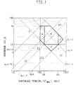
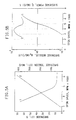
- B-filaments of the invention as prepared by Type I and Type II treatment processes of the invention, as described hereinabove, have a P s of 1.5 to 12 (g/d)% (1.3 to 11 dN/tex %), a M s of up to 5 g/d (4 dN/tex), and shrinkage S, such that (1-S/S m ) is 0.25 to 0.9 for RDR values of 1.4 to 1.9; a T(ST max ) between the T g and the T 1 of the polyester polymer; and a ST max of 0.1 to 0.5 g/d (0.1 to 0.4 dN/tex) (as indicated by Areas A and B in Figure 1) ; and the B-filaments of the invention are further characterized by a tenacity-at-10% extension (T 10 ) less than 3 g/d (3 dN/tex), a post-yield modulus (M py ), defined by ⁇ (1.2T 20 -1.07T 7 )/(1.2
- Preferred B-filaments of the invention as prepared by Type I and Type II treatment processes of the invention, as described hereinabove, are further characterized by a shrinkage S, such that (1-S/S m ) is 0.4 to 0.9; a T(ST max ) between the T g and the T ll of the polyester polymer; a T 10 less than 2.5 g/d (2.2 dN/tex), a M py of 2 to 10 g/dd (2 to 9 dN/drawn tex) which approximately corresponds to a birefringence ( ⁇ n ) of 0.04 to 0.1 providing good dyeability as indicated by RDDR values of at least 0.1; and sufficient tensiles for use as textile filaments as indicated by T 7 of at least 0.15 g/d (0.13 dN/tex).
- Especially preferred B-filaments of the invention are further characterized by a ⁇ S 1 value of less than 5 degrees over the temperature range of the polymer T 11 and T c,max ; and a ⁇ S 2 less than +3%.
- the invention also provides B-filaments being especially suitable for improved draw texturing feed yarns [Area A in Figure 1] for developing higher bulk at conventional texturing speeds or maintaining current levels of bulk at higher texturing speeds; wherein the B-filaments are prepared by heat treatment Type I of Type A filaments; wherein the B-filaments are characterized by having a RDR of 0.4 to 0.9; a shrinkage S, such that (1-S/S m ) is 0.25 to 0.9 with a ST max of 0.1 to 0.15 g/d (0.1 to 0.13 dN/tex) and a M s of up to 1.5 g/d (1.3 dN/tex); and further characterized by a T(ST max ) between the T g and the T ll of the polyester polymer.
- the invention also provides for B-filaments of enhanced tensiles, such as a T 7 of at least 0.15 g/d (1.3 dN/tex) and an initial modulus M i of at least 60 g/d (53 dN/tex), by low temperature drawing without post heat treatment (herein referred to as process Type III ) of B-filaments (as represented by Areas A and B in Figure 1 and described hereinbefore) at draw temperatures T D between temperatures T g and T 1 of the polyester polymer; wherein the drawn B-filaments of higher tensiles are further characterized by a T(ST max ) between T g and T 2 of the polyester polymer, with a ST max of 0.5 to 0.7 g/d (0.4 to 0.6 dN/tex); and a shrinkage S such that (1-S/S m ) is 0.4 to 0.9; a P s of 5 to 12 (g/d)% (4 to 11 dN/tex %) and a M s of 1.5
- the invention also provides improved flat "A-filament" yarns, especially suitable for tightly constructed woven fabrics [ Area D in Figure 1], by treating thermally stable Type A' filaments by Type II process of the invention (herein referred to as process Type IV ) wherein the changes in the thermal properties on the "thermally stable" A'-filaments are small, but sufficient to make the filaments suitable for both knitting and weaving where untreated A'-filaments were only suitable for knit fabrics); wherein the improved flat yarns are characterized by having a RDR of 1.4 to 1.9, a T 7 of at least 0.15 g/d (0.13 dN/tex) ; a shrinkage S, such that (1-S/S m ) is 0.95 to 0.9 and a ST max of 0.15 to 0.5 g/d (0.13 to 0.4 dN/tex) such to provide a P s of 1.5 to 5 (g/d)% (1.3 to 4 dN/tex %) with a M s of 1.5 to 5 g/d (
- the process of the invention also provides a simple route to mixed-shrinkage filament yarns (herein denoted as AB and as A'B yarns) comprised of A(or A') filaments and B-filaments wherein the A (or A') filaments and the B-filaments may be co-mingled, for example in a separate split process to form a mixed filament bundle (e.g., prior to air-jet texturing) or may be formed in a coupled spin/treatment process (cp) wherein the freshly spun A-filaments are, for example, divided into two bundles with one bundle being treated by process Type I or Type II to form B-filaments which are then combined with the untreated A-filament bundle to form a mixed-shrinkage AB filament yarn; or by treating in a split or coupled process a mixed A'A-filament bundle comprised of A' and A-filaments, where A' filaments are of such thermal stability that their shrinkage properties are not significantly affected by the treatment step (Type I or
- the A' filaments achieve their thermally stability , for example, by being of lower denier, odd cross section of significant surface-to-volume ratio; or the A and A'-filaments may be of the same dpf and cross-section, but are differentiated by their extrusion conditions; e.g., prior to extrusion, the polyester melt stream is divided into two melt streams, wherein one of the two melt streams is treated, for example, via injection of an agent into the melt stream that either enhances crystallization thus forming A'-filaments from A-filaments or injection of any agent that suppresses crystallization and thus forming A-filaments from A'-filaments on extrusion and attenuation, or alternatively, one the melt streams may be of different melt viscosity by use of higher shear spinneret extrusion capillaries fitted with metering capillaries such that the total pressure drop of the A forming capillaries is equal to that of the A' forming capillaries in order to maintain the same dpf of
- the filaments extruded at the lower melt viscosity will achieve lower SIC and become the A-filaments, while the filaments extruded at the higher melt viscosity will achieve higher SIC and become the A'-filaments.
- Spinning of melt streams which differ in polymer RV or in the degree to which they are modified by copolyester units may also be used to form A and A'-filaments.
- the process of the invention also provides for mixed-filament post-bulkable BC'-yarns comprised of B-filaments and of companion thermally stable C'-filaments of a different polymer substrate, such as of nylon by a coupled melt spinning/treatment process wherein the mixed filament bundle of B and C'-filaments may be prepared by co-spinning A and C'-filaments, forming a mixed-filament AC' bundle followed by co-treating the mixed-filament AC' bundle wherein in the A-filaments are transformed into B-filaments according to the invention and the nylon C'-filaments remain of low shrinkage.
- the B and C'-filament bundles may be formed in separate steps and co-mingled to provide a post-bulkable BC' mixed-filament yarn.
- the bulking of these mixed-filament yarns occurs on heat relaxation at temperatures above about T 11 but less than T c,max (preferably less than about T c,1 ⁇ 2 ) of the polyester polymer; and may take place in yarn form, such as in a hot air-jet texturing process or in the form of a weftless warp sheet in a warping process wherein the weftless warp sheet is permitted to hot relax before winding onto a beam or prior to being fed directly into a warp knitting machine or into a weaving loom or the bulk may be developed in fabric or garment form during dyeing and finishing.
- the processes of the invention may be extended to bicomponent filaments comprised of one component being thermally stable under the conditions of either process Type I or Type II and a second component being less thermal stability; e.g., an (A'/A) bicomponent filament which when treated according to the treatment processes of the invention (Type I or Type II) provides a (A'/B) bicomponent filaments which on exposure to heat will spontaneously provide filaments of torque-free helical crimp.
- an (A'/A) bicomponent filament which when treated according to the treatment processes of the invention (Type I or Type II) provides a (A'/B) bicomponent filaments which on exposure to heat will spontaneously provide filaments of torque-free helical crimp.
- thermoly stable component is of polyamide polymer (C') and the second component of lesser thermal stability is of polyester polymer (A) to provide a (A/C') biconstituent filaments which when treated according to the treatment processes of the invention (Type I or Type II) provide (B/C') biconstituent filaments which on exposure to heat will spontaneously provide filaments of torque-free helical crimping.
- the bicomponent and biconstituent filaments may be of a side-by-side (SBS) or of a sheath/core (S/C) configuration. Further, mixed deniers and/or cross-sections may be used to disrupt the tendency of helical crimped filament yarns from forming "follow-the-leader crimp" and thereby by provide for improved bulk and coverage (opacity).
- the treatment processes of the invention may incorporate a pretreatment step, wherein the untreated A, A', A/A', A/C', AA', and AC' filament bundles are passed under sufficient tension and velocity over a surface of selected roughness to provide sufficient thermal fictional heat to provide the treated filaments with asymmetric thermal stability (as described in part by Frankfort in USP Nos. 3,816,992, 3,861,133, and 3,905,077).
- Type V The treated filaments having irregular and asymmetric shrinkage behavior along-end are then treated by Type I, II, or III processes of the invention to provide on heat relaxation along-end filament crimping and filament bulk of a different nature than that achieved by mixed shrinkage filament yarns and by bicomponent or by biconstituent filament yarns
- This pretreatment process used in conjunction with Type I, II, or III processes of the invention is herein referred to as process Type V.
- the treatment processes (Type I, II, or III) of the invention may by applied to filaments of asymmetric cross-section, such as a "lop-sided peanut-shaped" filament wherein one side being larger has the shrinkage characteristics more like that of an A-filament while the smaller side has the shrinkage characteristics more like that of a thermally stable A'-filament such that the asymmetric filament is likened to an A/A' bicomponent filament yarn in its shrinkage behavior.
- asymmetric cross-section such as a "lop-sided peanut-shaped" filament wherein one side being larger has the shrinkage characteristics more like that of an A-filament while the smaller side has the shrinkage characteristics more like that of a thermally stable A'-filament such that the asymmetric filament is likened to an A/A' bicomponent filament yarn in its shrinkage behavior.
- the treatment processes (Type I, II, or III) of the invention may by applied to filaments of symmetric or asymmetric cross-section being comprised of an off-center longitudinal void of at least 10% (preferably at least 20%) by volume of the filament; wherein, the "solid" side of the filament has the shrinkage characteristics more like that of an A-filament while the side of the filament containing the void has the shrinkage characteristics more like that of a thermally stable A'-filament such that the hollow filament is likened to an A/A' bicomponent filament yarn in its shrinkage behavior.
- Example G for details
- the solid lines outline combinations of shrinkage properties that characterize various spin-oriented B-filaments of the invention ( Areas A and B) ; B-filaments of higher tensiles through low temperature drawing of spin-oriented B-filaments of Areas A and B ( Area C ); and low shrinkage flat filaments of improved tensiles by treatment of A'-filaments by process Type IV ( Area D ).
- B-filaments of Area B are especially suited for use in mix-shrinkage post-bulkable filament yarns, draw texturing feed yarns for improved bulk development, and where high shrinkage filament yarns for developing fabrics of more tight constructions than are possible by direct knitting or weaving of conventioal flat textile filament yarns.
- B-filaments of Area A are especially suited for use as draw texturing feed yarns where higher bulk is desireable.
- Low temperature drawn B-filaments of Area C are of higher tensiles without loss in dyeability as indicated by RDDR-values of at least 0.08.
- Improved low shrinkage flat yarns formed by treating Type A' filament yarns by process IV are especially suited for woven fabrics and for obtaining fabrics of tigher construction than posssible by direct knitting or weaving of conventional low shrinkage flat yarns.
- Fig. 1 Various conventional spin-oriented filaments spun over a spin speed range of about 500 m/min to about 7500 m/min are represented in Fig. 1 as follows: Area I for high shrinkage spin-oriented yarns (e.g., commercial POY); Area II for low shrinkage high speed spun direct-use yarns according to Knox; Area III for especially thermally stable highly oriented yarns, HOY (indicative of Type A'-filaments, described hereinbefore) as taught by Frankfort and Knox, and Collins et al.; Area IV for highly annealed (and/or relaxed) spun, drawn and draw-textured yarns; Area V for conventional spin/drawn (fully drawn yarns, FDY) textile yarns; Area VI for high shrinkage modulus "space-drawn" yarns, such as those disclosed by Davis et al in USP 4,195,161; and Area VII for high shrinkage filament yarns with high orientation (and thereby poor dyeability), such as disclosed by, Teijin (Shimazu et al)
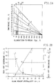
- Figure 2A is a representative plot of percent shrinkage S versus percent elongation-to-break (E B ) wherein Lines 1, 2, 3, 4, 5, and 6 represent (1-S/S m )-values of 0.9, 0.7, 0.6, 0.4, 0.25 and 0, respectively; and the curve shaped Line 7 represents a typical shrinkage versus elongation-to-break relationship for a series of yarns formed by increasing spinning speed, for example, wherein all other process variables remain unchanged.
- Changing other process variables such as dpf, polymer viscosity, capillary L/D 4 ) produces a "family" of similar S-shaped curves, essentially parallel to each other.
- the spin-oriented B-filaments of the invention are denoted by the "widely-spaced //////-area bordered by E B -values of 40% and 90% and (1-S/S m ) values of 0.25( Line 5 ) and 0.9 ( Line 1 ).
- the A-filaments used to form the B-filaments of the invention are denoted by the "densely-spaced" ///////-area bordered by E B -values of 40% and 90% and (1-S/S m ) values of 0.9 ( Line 1 ).
- the A'-filaments typically have (1-S/S m ) values greater than 0.95 (i.e., are further below Line 1).
- Figure 2B ( Curve I ) is a representative plot of shrinkage S of SOF having a wide range of elongations-to-break E B from 160% to 40% (corresponding to RDR-values of 2.6 to 1.4), spun using a wide range of process conditions (e.g., filament denier and cross-section, spin speed, polymer LRV, quenching, capillary dimensions, and polymer temperature T P ), versus percent volume crystallinity (Xv) from measured density, corrected for density of % pigment).
- process conditions e.g., filament denier and cross-section, spin speed, polymer LRV, quenching, capillary dimensions, and polymer temperature T P
- Xv percent volume crystallinity
- FIG. 3A is a representative plot of the peak temperature of "cold crystallization” (T cc ), as measured by Differential Scanning Calorimetry (DSC) at a heating rate of 20°C per minute (refer to Fig.12), versus amorphous birefringence (as defined in Frankfort and Knox); thus, the value of T cc is a useful measure of the amorphous birefringence (orientation) for filaments where measurement of birefringence is difficult.
- the A-filaments used herein to prepare the B-filaments of the invention have T cc values of 90°C to 110°C
- Figure 3B Line 1 is a representative plot of the M py versus total birefringence ( ⁇ n ); thus, for M py values above 2 g/d (2 dN/tex), the M py is a useful measure of total birefringence of spin-oriented, drawn, and textured filaments.
- the break in the linear relationship between M py and total birefringence is found to correspond to onset of major crystallization for spun yarns with increasing spin speed; but for a series of cold drawn yarns, the break represents the onset of significant increase in interchain order as noted by an increase in trans isomer content in the amorphous phase (determined by polarized infared spectroscopy).
- Line 2 is a plot of RDDR values, normalized to 1 dpf (1 dtex) after-boil-off and to an amorphous density of 1.335 g/cc, versus total birefringence ( ⁇ n ). Filaments of the invention have birefringence values of 0.04 to 0.12, and RDDR-values of at least 0.08. The RDDR-values may be greater than the linear relationship of Line 2 because of the effect of crystal size and percent crystallinity, in addition to orientation (i.e., birefringence) on dyeability of polyester yarns.
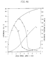
- Figure 4A is a plot of percent shrinkage S (or ST max for Curve 4) versus spin speed (mpm), taken as a measure of increasing SIO; where Curve 1 represents increasing shrinkage (i.e., S m ) in absence of SIC; Curve 2 represents shrinkage S versus spin speed with shrinkage decreasing (i.e., departing from Curve 1) at the onset of SIC which reduces shrinkage with increasing spin speed (typical of commercial POY); and Curve 3 represents shrinkage S versus spin speed wherein process conditions have been selected to "force" the onset of SIC at lower levels of SIO and is typical of the process used to form the A-filaments of the invention. Curve 4 is representative of the ST max for Curves 1, 2 and 3 versus spin speed.
- Curve 5 is representative of the shrinkage of nylon 66 spun yarns after equilibrated to standard relative humidity of 65% at 70°F (21°C).
- the shrinkage of nylon 66 modified with 5-10% copolyamides and of nylon 6 homopolymer spun yarns is slightly higher than that represented by Curve 5.
- Even higher shrinkages are possible with increasing modification with copolyamides as described by Knox et al in USP No. 5,137,666 and by Boles, et al. in USP No. 5,219,503.
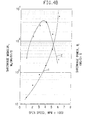
- Figure 4B is a semi-log (base 10) plot of the log of shrinkage modulus (M s ) and of shrinkage power (P s ) calculated from Curves 3 and 4 of Fig.4A, versus spin speed (mpm); wherein M s (Curve 1) is defined, herein, as the result of dividing the values of Curve 4 by those of Curve 3 (of Fig.4A) and plotting the result versus spin speed; and wherein P s ( Curve 2 ) is defined, herein, as the result of the product of values of Curve 3 and of Curve 4 (of Fig.4A) and plotting the results versus spin speed.
- M s Curve 1
- P s Curve 2
- Figure 5A is an analogous plot to Fig.4A for B-filaments formed by treatment of A-filaments by Type I and II processes of the invention; wherein Curve 1 is the plot of shrinkage S for B-filament yarns formed by treating A-filaments at temperature T 3 versus the spin speed (mpm) used in the preparation of the A-filament yarns; and Curve 2 is representative of the ST max for the B-filaments corresponding to Curve 1 versus spin speed.
- Figure 5B is an analogous semi-log (base 10) plot of the log of M s and of P s to that of Fig.4B; wherein the M s ( Curve 1 ) is defined, herein, as the result of dividing the values of Curve 2 by those of Curve 1 (both from Fig.5A) and plotting the result versus spin speed; and wherein P s ( Curve 2) is defined, herein, as the result of the product of values of Curve 1 and of Curve 2 (both from Fig.5A) and plotting the results versus spin speed.
- P s The values of P s are observed to reach a maximum as in Fig.4B, but also is followed by an apparent minimum not observed in Fig.4B; while M s ( Curve 1 ) increases with spin speed throughout this speed range as it did for B-filaments in Fig.4B ( Curve 1).
- the minimum for P s is believed to be associated with the thermal stability of the B-filaments formed by treating of the A'-filaments; wherein A-filaments -> A'-filaments with increasing spin speed (i.e. SIC); but where ST max continues to increase with spin speed by the process treatments of the invention.
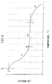
- Figure 6 is a plot of the logarithm of the modulus (stiffness) of a thermoplastic material, such as polyester, versus temperature.
- the modulus initially is relatively insensitive to temperature (denoted as the "glass" region (I) and begins to decrease at the (primary) glass-transition temperature T g and levels off at the secondary glass-transition temperature (T ll ), where the region between T g and T ll is often referred to as the "leather" region (II) and the secondary glass-transition temperature T ll is more commonly called the liquid-liquid transition temperature in open literature and also herein, and denotes the onset of the "ideal" rubber-like elastic region (III) and at higher temperatures the polymer begins to melt, noted as region IV.
- Polyester may be drawn between T g and T ll without significant crystallization. Crystallization, however, occurs in region III making the crystalline yarns of region III not “ideal” as to their elastic properties.
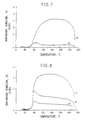
- Figure 7 is a superimposed plot of dynamic shrinkage tension (ST) values versus treatment temperature (T, C) for an undrawn POY (curve A) and for the corresponding drawn yarn (Curve B); wherein the undrawn POY (curve A) has a characteristic T(ST max ) below about 100°C and the drawn product (curve B) has a characteristic T(ST max ) typically between about 150°C and about 180°C (that is, in the range of the T c,1 ⁇ 2 and T c,max , where T c,1 ⁇ 2 is the temperature where the rate of crystallization is one-half of that at T c,max (refer to Fig.14 for a more detailed discussion).
- ST dynamic shrinkage tension
- Figure 8 is a similar superimposed plot, as in Fig.7, of dynamic shrinkage tension (ST) versus treatment temperature (T) for undrawn A-filaments ( Curve A );
- Curve B is of B-filaments prepared by treating A-filaments of Curve A per the invention at T c ° (i.e., about 120°C); and
- Curve C is of undrawn B-filaments prepared by treating A-filaments at T c,1 ⁇ 2 (i.e., about 150°C).
- the yarns represented by Curves B and C are indicative of the B-filaments prepared by process Type I and II, respectively.
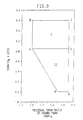
- Figure 9 shows the relationship between the relaxation/heat setting temperature (T R ) (where T R is measured in degrees C) and the residual draw-ratio of the drawn yarns (RDR) D for nylon 66 graphically by a plot of [1000/(T R +273)] vs. (RDR) D as described by Boles et al in USP No.5,219,503.
- This relaxation temperature vs. (RDR) D relationship is also preferably applied when co-drawing and heat treating or heat treating previous drawn co-mingled mixed-filament yarns comprised of nylon and polyester filaments.
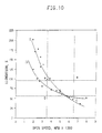
- Figure 10 is a representative plot of the elongations-to-break (E B ) of spin-oriented undrawn nylon 66 and polyester filament yarns versus spinning speed. Between about 3.5 Km/min and 6.5 Km/min (denoted by region ABCD) and especially between about 4 and 6 Km/min, the elongations of undrawn polyester and nylon filaments are of the same order.
- the elongation of the undrawn nylon filaments may be increased by increasing polymer RV (Chamberlin USP Nos. 4,583,357 and 4,646,514), by use of chain branching agents (Nunning USP No. 4,721,650), or by use of selected copolyamides and higher RV (Knox et al in USP No. 5,137,666).
- the elongation of the undrawn polyester may be increased by lower intrinsic viscosity and use of copolyesters (Knox in USP No. 4,156,071 and Frankfort and Knox USP Nos. 4,134,882 and 4,195,051), and by incorporating minor amounts of chain branching agents (MacLean USP No. 4,092,229, Knox in USP No. 4,156,051 and Reese in USP Nos. 4,883,032, 4,996,740, and 5,034,174).
- the elongation of polyester filaments is especially responsive to changes in filament denier and shape, with elongation decreasing with increasing filament surface-to-volume (i.e., with either or both decreasing filament denier and non-round shapes).
- Figure 11A is a representative dynamic Thermal Mechanical Analyzer (TMA) percent extension ( ⁇ L) vs. temperature plot (also referred to in the literature as "creep") under a 300 mg/d (0.265 dN/tex) load for A-filament yarn showing approximate values of the fiber T g , T ll , T cc , T c °, T c,1 ⁇ 2 and T c,max ).
- TMA dynamic Thermal Mechanical Analyzer
- Figure 11B is a representative plot of the derivative ( ⁇ L)/ ⁇ T) of the ⁇ L (same as from Fig. 11A) plotted versus temperature to show various thermal transition temperatures.
- Fig.11B provides a very useful technique to visualize thermal changes occurring prior to major crystallization (T c,1 ⁇ 2 ).
- Figure 12 is a representative DSC temperature scan of a Type A filament to show the glass-transition temperature (T g ), the peak temperature of cold crystallization (T cc ), the temperature of the onset of crystallization (T c °), the temperature of maximum rate of crystallization (T c,max ), the onset of melting (T m ') and the zero-shear melting point (T m °).
- Figure 13 is a representative dynamic shrinkage tension (ST) versus temperature scan of an A-filament; wherein the approximate values of the fiber T g , T(ST max ), and T c ° are easily discernable and T c,1 ⁇ 2 and T c,max are marked for reference.
- ST vs. T scans look more like a rounded "table top" wherein the thermal transitions between T(ST max ) and T c,max are not so easily determined from such a plot without sophisticated peak resolution computer analysis.
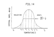
- Figure 14 is a representative plot of the crystallization rate versus temperature of polycondensation type polymers, such as polyesters and polyamides; wherein the values of T g and T m ° are marked and the values of T c °, T c,1 ⁇ 2 , and T c,max , correspond to temperatures along the x-axis T' 1 , T 1 and T c , respectively.
- polycondensation type polymers such as polyesters and polyamides
- T g , T ll , T c °, T c,1 ⁇ 2 , T c,max , and T m ° are approximately: 65-70°C, 95-100°C, 120-130°C, 150-160° C, 180-190°C, and 250-260°C, respectively.
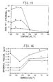
- Figure 15 is a representative plot of shrinkage (S) for B-filaments versus hot tube treatment temperature (not necessarily equal to yarn temperature due to less than perfect heat-transfer) for A-filament yarns spun at 4000 mpm ( Curve 1 ); 4500 mpm (Curve 2) and 5000 mpm ( Curve 3 ).
- the peak shrinkage S vs. steam pressure appears to be obtained at higher steam pressures at high spinning speeds (e.g., reduced exposure times).
- the peak pressure moves upwards as dpf increases, most likely because of limits of heat transfer rates for the larger cross-section filaments.
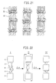
- Figure 21 is a schematic representation of a 3-phase fiber structure model to show crystalline regions (C), amorphous regions (A) and interface regions (B), herein referred to as "mesophase” which are meta stable, i.e., sensitive to low temperature treatments and may be either incorporated into the amorphous phase (A) or into the crystalline phase (C), depending on the treatment temperature, time at the treatment temperature, and the tension (or lack of tension) during the treatment.
- C crystalline regions
- A amorphous regions
- B interface regions
- Figure 22 shows different schematics of the fiber structure shown in Fig.21.
- schematic I represents high speed spun crystalline filaments of Type A comprised of a primary crystal phase (C), a secondary crystal phase (B), referred to as mesophase, above and amorphous phase (A).
- ⁇ H thermal treatments
- the mesophase is melted-out, providing a thermally unstable amorphous phase held together by a primary crystal phase as represented in the center schematic II.
- this structure is transformed into a re-crystallized phase represented in schematic III on the right.
- the metastable phase (B) is not isolated, but readily goes to a conventional stable crystalline structure.
- the invention permits the isolation of this metastable phase B, and consequently the formation of the novel B-filaments that have surprising new properties.
- Figure 23 represents an application of the existence of this metastable phase B.
- the FTT Yarn Bulk i.e., of false-twist textured yarns
- the spin speed of various precursor undrawn feed yarns Despite an increase in crystallinity (density) and decrease in shrinkage S, the textured yarn bulk continually increases with increasing spin speed (Curve 1) with increasing spin speed. If the extent of crystallization is "totally" suppressed by use of water quenching (as described by Vassilatos in USP No.
- the extent of the "B" phase can be increased as indicated by an increase in the shrinkage of the feed yarn, there is observed an increase in textured yarn bulk as represented by points 1 -> 2-> 3-> 4->5.
- the process of the invention provides uniform feed yarns of high shrinkage and shrinkage power especially suitable for high speed (low residence time) texturing.
- Alternatives, such as use of long delay quench zones and "too" hot polymer (used in Fig. 23) provide higher bulk but unacceptable along-end uniformity.
- Figure 24A is a plot of measured shrinkage S of a AB mixed filament yarn comprised of 70/17 denier B-filaments and 70/100 denier A-filaments versus the shrinkage of the B-filament component.
- Line 1 is the expected trend and Line 2 is observed for high shrinkage filaments of undesireably low ST max , i.e., being incapable of overcoming the inter-filament friction and entanglements to develop the expected high shrinkage in a mixed AB filament yarn.
- Figure 24B (line 1) is the expected plot of measured STmax for AB mixed filament yarns vs. the ST max of the B-filament component; line 2 is a plot of calculated ST max values (weight average ST-values based on total denier of each component) versus the observed STmax-values. Line 2 shows that the expected ST max of a composite yarn is less than that of a single high ST max filament yarn and is well represented by the weighted average of A and B components.
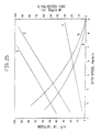
- Figure 25 is a representative plot of the initial modulus of 65 RV Nylon 66 SOY (Line 1) and of 21 LRV 2GT polyester SOY ( Line 2 ), wherein the zero-shear (Newtonian) melt viscosity of 21 LRV polyester polymer is about the same 65 RV Nylon 66 polymer.
- Line 3 is a plot of the initial modulus of polyester filaments heat treated according to Type II process of the invention.
- Lines 4 and 5 are plots of the percent of the polyester core vs.
- IV 0.07238[1.28(LRV+1.2)] 0.658
- T m ° zero-shear melting point
- T g glass-transition temperature
- the said polyester polymer is a linear condensation polymer composed of alternating A and B structural units, where the A's are hydrocarbylenedioxy units of the form [-O-R'-O-] and the B's are hydrocarbylenedicarbonyl units of the form [-C(O)-R"-C(O)-], wherein R' is primarily [-C 2 H 4 -], as in the ethylenedioxy (glycol) unit [-O-C 2 H 4 -O-], and R" is primarily [-C 6 H 4 -], as in the 1,4-benzenedicarbonyl unit [-C(O)-C 6 H 4 -C(O)-], such to provide a sufficient number of ethylene terephthalate, [-O-C 2 H 4 -O-C(O)-C 6 H 4 -C(O)-] repeat groups so to maintain the T m ° between about 240°C and about 280°C Suitable poly(ethylene terephthalate), here
- Polyester polymers used herein, may, if desired, be modified by incorporating ionic dye sites, such as ethylene-5-M-sulfo-isophthalate residues, where M is an alkali metal cation, for example in the range of about 1 to about 3 mole percent, and representative chain branching agents used herein to affect shrinkage and tensiles, especially of polyesters modified with ionic dye sites and/or copolyesters, are described in part by Knox in USP No. 4,156,071, MacLean in USP No. 4,092,229, and Reese in USP Nos. 4,883,032; 4,996,740; and 5,034,174.
- ionic dye sites such as ethylene-5-M-sulfo-isophthalate residues, where M is an alkali metal cation, for example in the range of about 1 to about 3 mole percent
- representative chain branching agents used herein to affect shrinkage and tensiles are described in part by Knox in USP No.
- DEG diethylene glycol
- the treatment process of the invention improves (transforms) the shrinkage properties of low shrinkage crystalline spin-oriented (undrawn) direct-use filament yarns (Type A), by post-treating the A-filaments in split or coupled (on-line) processes by anyone of the hereinbefore mentioned processes (I cp,sp or II cp,sp ) to provide spin-oriented Type B filament yarns; i.e., yarns of high P s with all of the desired characteristics listed hereinbefore.
- the treatment process consists of rapidly heating followed by rapidly cooling Type A-filaments under tension prior to winding up the newly formed B-filament yarns into packages or into a beam of many yarns.
- an increase tension is observed with essentially no permanent change in filament denier, wherein the increase in process tension is in the range of about the improvement in shrinkage tension (ST max ) of the treated A-filaments; i.e., about ST max (B)-ST max (A).
- ST max improvement in shrinkage tension
- the "heat” may be provided by steam jets, hot tubes, microwave, low friction heated surfaces, etc. Each will require careful selection of process variables (steam pressure and temperature, hot tube temperature, diameter, length, etc.) to achieve the desired rapid heat transfer (heating and cooling) necessary to transform Type A-filaments into Type B-filaments of desired shrinkage properties.
- the process of the invention provides a careful selection of heat treatment temperature and rates of heating and cooling that destabilize the crystalline structure of the A-filaments and prevents re-stabilization of the newly formed fiber structure (of the B-filaments).
- the ongoing process of re-crystallization re-stabilizes the "intermediate" structure" (herein referred to as a "meso--structure") of the B-filaments such that the high shrinkage power of the treated A-filaments is not realized.
- the processes of the invention develop the desired "meso-structure" of the B-filaments and inhibit the rapid re-stabilization of the "meso-structure" from occurring and thereby improving the properties of undrawn low shrinkage power A-filaments to provide undrawn high shrinkage power B-filaments.
- Type I and Type II B-filaments differ in their T(ST max ) and in their RDDR values.
- Type I B-filaments typically are of higher RDDR and T(ST max ) of less than about 100°C (i.e. less than about the polymer T ll ); while Type II B-filaments typically have lower RDDR than the A-filaments from which they were formed and T(ST max ) values are about 10°C higher.
- Combining Type I and Type II B-filaments provides a simplified route to differential shrinkage and dye rate mixed B I B II -filament yarns when dyed under atmospheric conditions without dye carriers.
- the high shrinkage B-filament yarns according to the invention may be used as direct-use textile yarns, but may also be used as preferred draw feed yarns as in draw-warping, draw air-jet texturing, and draw false-twist texturing wherein Type I B-filaments are selected if high dyeability is important and Type II B-filaments are selected where high ST max and T(ST max ) values are important for providing for improved stability in especially high speed textile processing.
- the Type of B-yarn is selected based on specific needs of the textile processing and the end-use fabric requirements.
- the level of filament bundle interlace and type/level of finish are also selected based on the downstream processing needs and aesthetics desired.
- Soft bulky yarns are provided from use of mixed-filament yarns comprised of high shrinkage B-filaments of "high” dpf (typically about 2 dpf for top weight fabrics) and low shrinkage A'-filaments of "low” dpf, preferably less than 1; e.g. 0.2 to 0.8 dpf (0.2 to 0.9 dtex/filament), with the low shrinkage fine denier A'-filaments providing the soft surface of the bulky yarn and the heavier dpf "core” filaments providing the fabric with improved “body” and “drape” (i.e., less “mushy”).
- Increasing the dpf of the B-filaments increases the firmness of the fabric made from the mixed A'B-filament yarns.
- the frictional characteristics may be enhanced to be more silk-like by use of silicon dioxide versus titanium dioxide delusterants.
- Other inert metal oxides may be used as delusterants.
- the hydrophilicity of the filaments may be enhanced by using undrawn filaments treated during spinning with caustic spin finish as taught by Grindstaff and Reese in USP No. 5,069,844).
- undrawn polyester/nylon mixed-filament yarns may be treated according to the invention to provide for polyester filaments of high shrinkage and high shrinkage tension, while the high speed spin-oriented nylon 66 filaments typically have shrinkages in the range of about 3-6%.
- the low modulus nylon filaments will provide predominately form the surface of a bulky polyester/nylon filament yarn.
- heat treating according to the processes of the invention of undrawn A/A'-bicomponent filaments provides a simple route to helical crimped bulky A'/B-bicomponent filament yarns by using filament components of different thermal stability (e.g., A/A' polyester bicomponent filaments and A/C' polyester/nylon biconstituent filaments (especially wherein the polyester (A) is modified per the teachings of Jennings in USP No. 4,702,875 which reduces the tendency of the polyester (A) and nylon (C) components to separate.
- filament components of different thermal stability e.g., A/A' polyester bicomponent filaments and A/C' polyester/nylon biconstituent filaments (especially wherein the polyester (A) is modified per the teachings of Jennings in USP No. 4,702,875 which reduces the tendency of the polyester (A) and nylon (C) components to separate.
- Single polymer torque-free helical crimp filaments may be provided by asymmetrically heating via localized friction, as described by Frankfort (USP No. 3,905,077) of crystalline low shrinkage polyester SOF and then passing said asymmetrically heated filaments through one of the heat treatment steps according to the invention or by providing asymmetric filaments such that they are characterized by differing radial shrinkage power and then passing such a filament yarn through one of the heat treatment step of the invention.
- mixed-filament yarns may be prepared according to the invention from undrawn feed yarns by incorporating filaments of different deniers and/or cross-sections (including filaments of one or more longitudinal voids) to reduce filament-to-filament packing and thereby improve tactile aesthetics and comfort.
- Unique dyeability effects may be obtained by co-mingling filaments of differing polymer modifications, such as homopolymer polyester dyeable with disperse dyes and ionic copolymer polyester dyeable with cationic dyes or disperse dyeable polyester and acid dyeable nylon or cationic dyeable polyester and acid dyeable nylon.
- Sheath/core A/A' bicomponent filaments may be used to provide the desired helical crimp formation on treatment according the invention, but also provide a surface of desired dye chemistry (e.g., acid-dyeable nylon sheath and disperse dyeable polyester core or cationic-dyeable polyester sheath and acid-dyeable core).
- desired dye chemistry e.g., acid-dyeable nylon sheath and disperse dyeable polyester core or cationic-dyeable polyester sheath and acid-dyeable core.
- Chemically active liquid-film and plasmas may be incorporated in the treatment step of the invention to provide modified filament surfaces, e.g., for increase in hydrophilicity and stain resistance.
- the fine filament yarns of this invention are also suitable for warp-drawing, air-jet texturing, false-twist texturing, gear crimping, and stuffer-box crimping, for example; and the improved low shrinkage filament yarns are desireable for use as direct-use flat textile yarns and as feed yarns for air-jet texturing and stuffer-box crimping wherein no draw need be taken and the low shrinkage is desireable so as not to lose tensiles during such no-draw texturing.
- the filaments (and tows made therefrom) may also be crimped (if desired) and cut into staple and flock.
- the fabrics made from these improved yarns may be surface treated by conventional sanding and brushing to give suede-like tactility.
- the filament surface frictional characteristics may be changed by selection of cross-section, delusterants, and through such treatments as alkali-etching.
- the improved combination of filament strength and uniformity makes these filaments, especially suited for end-use processes that require fine filament yarns without broken filaments (and filament breakage) and uniform dyeing with critical dyes.
- the fine denier filament polyester yarns of the invention are especially suitable for making of high-end density moisture-barrier fabrics, such as rainwear and medical garments.
- the fine filament yarns may also be used as covering yarns of elastomeric yarns (and strips), preferably by air entanglement as described by Strachan in USP No. 3,940,917.
- the fine filaments of the invention may be co-mingled on-line in spinning or off-line with higher denier polyester (or nylon) filaments to provide for cross-dyed effects and/or mixed-shrinkage post-bulkable potential, where the bulk may be developed off-line, such as over feeding in presence of heat while beaming/slashing or in fabric form, such as in the dye bath.
- the degree of interlace and type/amount of finish applied during spinning is selected based on the textile processing needs and final desired yarn/fabric aesthetics.
- any type of draw winding machine may be used; post heat treatment of the feed and/or drawn yarns, if desired, may be applied by any type of heating device (such as heated godets, hot air and/or steam jet, passage through a heated tube, microwave heating, etc.); finish application may be applied by convention roll application, herein metered finish tip applicators are preferred and finish may be applied in several steps, for example during spinning prior to heat treatment and after said heat prior to winding; interlace may be developed by using heated or unheated entanglement air-jets and may be developed in several steps, such as during spinning and after heat treatment and other devices may be used, such by use of tangle-reeds on a weftless warp sheet of yarns.
- any type of draw winding machine may be used; post heat treatment of the feed and/or drawn yarns, if desired, may be applied by any type of heating device (such as heated godets, hot air and/or steam jet, passage through a heated tube, microwave heating, etc.); finish application
- thermodynamic transition temperatures such as T g are calculated according to the method of R. F. Boyer ["Order in the Amorphous State of Polymers", ed. S. E. Keinath, R. L. Miller, and J. K.
- T x (degrees C) ⁇ K x (T m °+273)-273 ⁇ , where the constant "K x " is 0.65, 0.7, 0.7125, 0.725, 0.75, 0.775, 0.80, 0.825, and 0.85, respectively for T x corresponding to: T g , T ll , T 1 , T 2 , T c °, T 3 , T c,1 ⁇ 2 , T 4 , and T c,max ; wherein T m ° is the polymer zero-shear melting point measured by DSC at a heating rate of 20°C/min. Test methods used herein for characterizing companion nylon polymer and filaments are given in Knox et al in USP No. 5,137,366 and in Boles et al in USP. No. 5,219,503.
- Type I and II A-filament -> B-filament (Areas A and B in Fig. 1).
- Type III B-filament + low temp. draw -> higher tensile B-filaments (Area C in Pig.1).
- Type IV A'-filament -> A' filament of higher shrinkage and shrinkage tension, but still having a (1-S/S m ) value greater than 0.9, via treatment by Process Type II.
- Type V Pretreatment of A, A/A', A/C, AC' filaments by asymmetric surface heating followed by Process Types I, II, or III.
- Type VI Relaxation of B, A'/B, B/C', A'B, BC' filaments followed by redraw and second relaxation.
- Type VII Drawing of Type A-filaments at draw temperatures between the polymer T g and T ll without post-heat treatment to provide uniform partially or fully drawn B-filaments.
- the invention lends itself to further variations and ways to take advantage of the benefits of the yarns of the invention in various drawing and/or heat treatment processes as described hereinafter.
- the following examples further illustrate the invention and are not intended to be limiting.
- Example I undrawn crystalline SOF yarns of Type A are prepared over a wide range of melt spinning process conditions and before winding up into a package of yarn, the A-filaments are rapidly heated by passing through a superheated steam chamber of varying temperatures and pressures.
- the polyester polymer of 20.8 LRV (0.65 IV) was melted to a temperature T p of 293-295°C, approximately 40°C above the polymer melting point T m of about 254-256°C.
- the polymer contained 0.3% Ti0 2 as a delusterant.
- the filament yarns were spun using 17-hole spinnerets of DXL of 15 mils (0.381 mm) x 60 mils (1.905 mm).
- the mass flow rate (w, grams per minute) is metered to provide filaments of denier 2.1, 2.9, and 4.1 at withdrawal spin speeds (V) of 4500 ypm (4115 mpm) to 5300 ypm (4846 mpm).
- V withdrawal spin speeds
- the freshly extruded filaments are protected with an unheated short 2-inch (5 cm) shroud to protect the face of the spinneret from being cooled by stray air currents and then rapidly quenched using radially directed room temperature air at a flow rate of 18.5 mpm using a radial quench chamber, as described in Knox, and the fully quenched filaments are converged into a filament bundle using a metered finish tip applicator guide at a distance L c of 32 inches (81 cm).
- the low shrinkage crystalline filament bundle at a temperature below the polymer T g is passed through a steam chamber of varying temperature and pressure, wherein the filaments are rapidly heated and then rapidly cooled; followed by application of interlace and then wound up into packages.
- Tables 1A through 1E Detailed process and product results are summarized in Tables 1A through 1E.
- the shrinkage of the crystalline low shrinkage A-filaments is observed to increase with steam pressure and reach a maximum and then decrease with increasing pressure.
- the peak steam pressure increases as the spin speed increases for a given filament denier and increases with filament denier at a given spin speed.
- all filaments have a T(ST max ) of less than 100° C; i.e., less than about the calculated thermal transition T ll of about 96°C for a polyester polymer T m ° of 254°C, and herein are said to have been treated by Process Type I versus Item 1A-8 filaments which are said to have been treated by Process Type II.
- Example II repeats Example I except for use of 27-hole spinnerets.
- the finer filaments provided by the 27-hole spinneret at the same mass flow rate provides for higher STmax, but also lower shrinkage S; hence giving comparable P s , but higher M s
- Example III the low shrinkage crystalline SOY were prepared according to Example I, except 34-capillary spinnerets were used to extrude polymer at T p of 290 C and quenched by a cross-flow quench chamber fitted with an unheathed 2-inch (5 cm) screen mesh shroud, and the filament bundle being converged at 30-inches (76 cm). Process details are given in Table 3.
- Example IV repeats Example III, but at lower steam pressures and steam temperatures. Most of the conditions did not supply sufficient heat to alter the crystalline feed filament yarns (Type A). For good quality of steam (i.e., no condensation) steam temperature of 245°C was selected. It is possible that if the residence time was increased that the conditions in Example 3 may have provided B-filaments. Detailed summary is given in Table 4.
- Example V 20.1 LRV (0.64 IV) homopolymer polyester polymer containing about 0.3% Ti0 2 as a delusterant was extruded at a T p of 297°C through 48 capillaries of diameter (D) of 0.25 mm and of length (L) of 0.50 mm and the filaments were rapidly quenched using cross-flow air at 18°C and the fully quenched filaments were converged into a filament bundle using a metered finish tip applicator guide and withdrawn at speeds between 3750 to 6000 mpm and then prior to winding into packages, the filament bundle at a temperature below the polymer T g was passed through a 200 cm hot air tube at temperatures from 120°C to 180°C Thermocouples indicated that for this particular tube design that for the exiting air (at these high withdrawal speeds) to reach 160°C, a 250 cm tube would be required and to reach 180°C that a 300 cm tube would be required.
- filament bundles treated at process temperatures in excess of about 150°C were heated to temperatures of at least about T c,1 ⁇ 2 ; and are not of the invention with an inferior combination of shrinkage and dyeability properties.
- the tension increase for filament bundles reaching temperatures less than about T c,1 ⁇ 2 was on the order of the improvement in ST max versus the untreated crystalline SOY.
- the length of the hot tube, temperature of the air (especially the exiting temperature), diameter of the tube, spinning speed, total yarn denier, number of filaments, and percent finish-on-yarn (FOY) determines if the filaments are exposed to temperatures of at least about T c,1 ⁇ 2 and therefore it is not readily possible to assume that based on tube temperature alone that the yarn has been treated at filament temperatures greater than T c,1 ⁇ 2 .
- Detailed summary is given in Table 5.
- Example VI filament yarns were spun using conditions similar to that of Example V, except that a short 100 cm tube was used for treatment of the fully quenched yarns. Other process details are given in Table 6. All the items are characterized by T(ST max ) values less than 100°C and therefore indicate that even at hot tube temperatures of 180°C, the actual filament temperatures most likely did not exceed T c ° (at least not for sufficient length of time) and did not exceed filament temperatures of T c,1 ⁇ 2 and therefore all items of Example VI are considered to be of Process Type I.
- Example VII the treated yarns of Example VI were further improved by cold drawing to final elongations in the range of 30% to 50%.
- Low shrinkage yarns i.e., characterized by a (1-S/S m ) value of at least about 0.9
- high shrinkage treated yarns had to be cold drawn to elongations less than about 40% and preferably to about 20-40% to avoid the possibility of thick-thin sections leading to dye nonuniformities.
- the drawing increased the treated yarns shrinkage S and ST max values, their T(ST max )-values remained essentially unchanged.
- Process Type III This process of coupling Process Type I followed by cold drawing without post heat treatment is designated, herein as Process Type III of the invention.
- Process III can be coupled with the on-line spin/treatment process of Type I cp or may be carried out in a separate step as in cold drawing of Type I cp B-filaments in the from of a weftless warp sheet or in air-jet texturing.
- the Process Type III yarns may be pre-bulked if desired, such as overfeeding in a heated relaxation step as part of the warp-draw and air-jet texturing processes.
- Example VIII selected B-filaments formed in Examples 1 and 2 are warp-drawn using a wide range of conditions. Cold drawing increased STmax, but did not significantly increase shrinkage S. This cold-drawing B-filaments provides a simple route to flat yarns of very high STmax at low shrinkage S values versus conventional spin/draw technology. Details are summarized in Table 8.
- Example IX is a summary of results of drawing Type A filament yarns (DUY) from Tables I-III in parent case, now a Patent USP 5,066,447. Warp-drawing results offer direct-use yarns. The conditions selected in the parent case did not provide B-filament yarns. Details are given in Table 9.
- Example X Type A-filaments are drawn at speeds in the range of 200 to 300 mpm without post heat treatment. If the draw temperature T D is between about the polymer T g and the polymer T c ° (preferably about the polymer T ll ), then improvements in the shrinkage properties of the low shrinkage crystalline Type A filaments are observed. However, if the draw temperature is above the cold crystallization temperature T cc of the filaments, which decreases with spin orientation of the amorphous regions (see Figure 2A) and is between about T ll and T c ° of the polymer, then the improvement in shrinkage properties is reduced. Type B filaments formed by this drawing process are designated herein as Type VII and is especially suited for warp-drawing and for air-jet texturing. Process and product data are summarized in Table 10.
- Example XI a low shrinkage A'-filament yarn formed by spinning at 6000 ypm (5486 mpm) per Frankfort and Knox teachings was treated at various temperatures in the relaxed and taut conditions. Various fiber structure parameters were measured. None of the conditions transformed the spun A' filament yarn into a B filament yarn and the filaments of this example are considered to be of sufficient thermal stability that it would also not be affected significantly by Processes of Type I-V and hence are designated as A' filaments.
- the fiber structure data suggests that an A'filament is characterized by a density of at least about 1.38 g/cm 3 and an average crystal size of at least about 60 angstroms and a shrinkage less than about 4-5%. Details are summarized in Table 11.
- Example XII Type A filaments prepared according to Knox were relaxed and taut annealed over the temperature range of 60 to 240°C dry heat; and relaxed and taut annealed in hot water. None of these treatments transformed the A filaments into B filaments supporting that rapid heating/cooling is required to "catch" the intermediate metastable mesophase structure, herein referred to as "B", before being stabilized into a A'-state (see Fig.22 - I,II,and III. Details are summarized in Table 12A and 12B.
- Example XIII the A-filaments of Example XII were drawn at draw-ratios (DR) of 1.0, 1.05, and 1.1 to simulate commercial hot aqueous slashing and tenter frame finishing process steps. None of the conditions transformed the Type A-filaments into Type B-filaments. confirming the results of Example XII. Details are summarized in Table 13.
- Example XIV various spin-oriented filament yarns were spun to provide different levels of shrinkage S and cospun mixed-filament yarns comprised of filaments differing in shrinkage. These mixed-shrinkage filament spin-oriented yarns did not have sufficient P s to develop bulk in tight knit and woven fabric constructions and such filament yarns are not considered to be yarns of the invention. Results are summarized in Tables 14A and 14B, respectively.
- Example XV various mixed-filament yarns were prepared of the type A'A and treated to transform the mixed-filament yarns into Type A'B yarns. The difference in shrinkage S and ST max were measured. The yarns were knit into circular tubing and boiled off to develop bulk via mixed-shrinkage. A'B yarns having P s values of at least about 1.5 g/d was required to develop significant bulk. The B-filaments of the invention used for mix-shrinkage yarns are characterized by P s values of at least 1.5 g/d (1.3 dN/tex). Results are summarized in Table 15.
- Example XVI mixed-filament yarns of varying filaments deniers were provided by combining filament bundles of two spin packs into a single bundle for ease of experimentation.
- Example 17 mixed-filaments yarns are warp-draw or permitted to relax to demonstrate pre-bulking of the mixed-filament A'/B yarns.
- Yarns that were relaxed by 0.93 provided bulk.
- Drawing did provide for greater shrinkage yarns which, if permitted to relax in a 3rd step (i.e , in the fabric) would have generated bulk (such as Item 17A-4 with a net draw of 1.2 and a shrinkage of 19.3% and a P s of about 7.5 (g/d)% (6.6 (dN/tex)%). If the warp (draw/relax) machine had been provided with 3 or more draw/relax zones, then bulk can be developed and enhanced by a relax-redraw-relax process (herein called provess Type VI). Such a process also is known to provide for increase in dyeability. Details are given in Table 17A,B.
- Example XVIII fabrics using 50 denier (56 dtex) 47 filament textured yarns in the warp with a 70 denier (78 dtex) 102 filament filling yarn comprised of 35 denier (39 dtex) 34 filament high shrinkage component (Type B) having a 17% shrinkage and a 35 denier (39 dtex) 68 filament low shrinkage microdenier component having a 4% shrinkage(Type A') and a 150 denier (167 dtex) 168-filament filling comprised of 75 denier (83 dtex) 68 filament high shrinkage component having a 15% shrinkage (Type B) and a 75 denier (83 dtex) 100-filament micro-denier low shrinkage component of about 4% (Type A').
- the fabrics were relaxed scoured at 212°F (100°C) to allow development of bulk from the shrinkage of the mixed shrinkage filaments of the mixed-filament filling yarns.
- the fabrics were then dyed in a jet dyeing machine using normal polyester dyeing conditions necessitated by the higher dpf polyester warp .
- Heat setting at width was carried out at a lower than normal temperatures to maintain the bulk developed during scouring and jet dyeing and to enhance the overall aesthetics. Evaluation of fabric handle of these fabrics shows that the mixed-dpf mixed-shrinkage properties of the yarns add to the stiffness, bounce, crispness, and scroop, properties much desired in a microdenier fabric to simulate silk like handle.
- the bulk of the fabrics are the comparable to that of fabrics made with 100 % textured warp and filling yarns.
- Data for the spinning of the various yarns are given in Table 18. Further improvements may be made by using three component A'B 1 B 2 mixed-shrinkage yarn so to provide a wider (and uniform) distribution of shrinkage.
- Example XIXA-D nylon POY are spun and warp-drawn to different elongations showing the feasibility of uniformly partial drawing of nylon, making it an acceptable co-draw companion yarns with A-filaments of the invention or as undrawn companions for treatment by processes of Type I or II followed by co-drawing by process Type III to given uniform mixed-shrinkage polyester/nylon filament yarns (Table XIX is taken from co-pending application Boles 07/532,529 and 07/753/769.
- the post-yield modulus based on T 20 and T 7 -values were calculated for Items 1-12 and 24-31; but were calculated based on T 10 and T 7 -values for Items 13-23 as noted by the *.
- the PYM-values from T 10 and T 7 are more variable than those from T 20 and T 7 -values; but both show a general trend of increase in PYM a decrease in RDDR where there was not such a trend using T 7 , T 10 , or T 20 as a single parameter to estimate dye rate.
- the values for the various B-filaments (1-23) are compared to commercial yarns and in general are found to be greater.
- a value of RDDR of at leaat about 0.1 is preferred and a value at least about 0.150 is especially preferred.
- Such values (especially 0.150 and greater) are considered to be atmospheric dyeable without carriers for most shades, especially with low to medium energy dyes.
- the yarns of the invention have a T(ST max ) less than about T c ° and preferably less than T 1 and especially less than about T ll ; wherein the values of T c,1 ⁇ 2 , T c °, and T ll .are calculated hereinbefore from the zero-shear melting point (T m °) of the polyester polymer. Details are summarized in Table 20.
- Example XXI one mode of the process of the invention (i.e., using a heated tube) for providing high shrinkage polyester filament is compared to a prior art hot tube process, also for providing high shrinkage polyester filaments; namely as described in EPA-0207489 (referred to in this Example XXI as Shimazu).
- Shimazu taught use of polyester polymer of intrinsic viscosity (IV) broadly covering the range of 0.4 to 0.9, but also taught that his polymer should be melted at a temperature T P higher than 290°C (page 12, line 25).
- the polymer melt temperature (T P ) is selected based on the polymer's melting point (T m °), which is in turn dependent on the polymer composition, e.g., IV, whether modified with copolyesters or by the addition of ionic monomeric units for ionic dyeability, etc, and our polymers are of IV in the range of 0.5 to 0.7, and the T P is controlled within the range of 20°C to 50°C above the selected polyester polymer's melting point (T m °).
- the polymer melt is extruded directly into a cooling chamber (preferably a radial cooling chamber fitted with a thin non-heat conductive gasket such that the distance between the point of extrusion, the face of spinneret (that is usually recessed slightly), and the point of air impingement is minimized to about 2-5 cm) where the cooling medium is typically air in the range of 10°C to 25°C.
- a cooling chamber preferably a radial cooling chamber fitted with a thin non-heat conductive gasket such that the distance between the point of extrusion, the face of spinneret (that is usually recessed slightly), and the point of air impingement is minimized to about 2-5 cm
- the cooling medium is typically air in the range of 10°C to 25°C.
- a "second quench zone" comprised of a protective open air chamber at room temperature or into a cross-flow air chamber to insure complete attenuation to temperatures less than the polymer T g (i.e., to a final stable structural state prior to convergence and application of finish and/or prior to any additional processing, i.e., by Type I or Type II heating and cooling.
- the heated shroud used by Shimazu retards crystallization and favors orientation, thereby providing filaments of higher orientation but of lower dyeability than filaments prepared by our process without such heated shroud.
- Shimazu's filaments are "conditioned” in a heated chamber.
- Shimazu's conditioning chamber is a tube of 80 to 200 cm in length heated to 120° to 160°C.
- the yarns of both processes may be wound up at speeds in an overlapping range of 4000 to 6000 mpm, but the process of the invention may use lower withdrawal speeds, e.g., as low as 2000 mpm for spinning micro-denier filaments (e.g., less than 1 dpf (1 dtex/filament)).
- the process differences from Shimazu's process include our further requirement that the yarn entering the conditioning zone, not only be at a temperature for structural stability and uniformity (i.e., less than polymer T g ), but also be a stabilized "textile yarn" (denoted herein as an A-filament yarn) of shrinkage S, such that (1-S/S m ) is at least about 0.9.(i.e., less than about a nominal shrinkage S of about 10%). No such structural condition is required or disclosed by Shimazu.
- Example A the shrinkages S and ST(max) for the high P s B-filaments are compared with AB mixed-filament yarns.
- the shrinkage S is determined by the higher shrinkage component (Fig. 24A- Line 1 ); but if the high shrinkage component has very low shrinkage tension, such as conventional POY, then the observed shrinkage S for the AB-filament yarns is significantly less that predicted from that of the high shrinkage component (Fig. 24A- Line 2 ).
- the "scattered" data assumes that the shrinkage tension of a AB-filament yarn is equal to that of the filaments of the highest ST max -values (Line 1); and Line 2 represents the calculated (ST max ) AB values based on weighted values of the ST max values of the individual components.
- the mixed-filament yarns of the invention are characterized by a yarn average ST max of at least 0.1 g/d (0.1 dN/tex) wherein the individual B-filaments have a ST max of at least about 0.15 g/d (0.13 dN/tex) ; preferably a yarn average ST max of at least about 0.15 g/d (0.13 dN/tex) wherein the individual B-filaments have a STmax of at least about 0.2 g/d (0.2 dN/tex).
- Example B filament yarns spun between 3000 and 6500 mpm were drawn false-twist textured at 220°C and bulk of the textured yarns were measured according to Frankfort and Knox and plotted versus spinning speed of the draw feed yarn (See Figure 23). Bulk is found to increase with spinning speed as previous taught by Frankfort and Knox. The bulk also increased with texturing speeds (at least for the case presented here from 700 to 800 mpm).
- the increase in bulk with spin speed is attributed to higher stress-induced orientation (SIO) which decreases the cold crystallization temperature T cc of the feed yarn (see Figure 3A) and increases the rate of crystallization; further the crystal size increases 8-16X in volume providing larger intercrystalline regions which permits greater mobility of the amorphous chains (i.e., of greater free-volume as supported by a decrease in the filament T g as measured by rheovibron and discussed in detail in Frankfort and Knox) and the increase in mobility of the amorphous chains facilitates crystallization (and thereby bulk development) in high speed texturing.
- SIO stress-induced orientation
- Example C the A-filaments used as feed filaments in this invention may be combined with high speed spun nylon filaments (such as those prepared according to Knox et al in U.S.P. No.5,137,666 and Boles et al in USP No. 5,219,503 to provide a mixed polyester (A)/nylon (C') filament yarn which may be uniformly drawn with or without heat as taught by Boles et al in U.S.P. Nos. 5,229,060 and 5,261,472.
- a mixed-shrinkage post-bulkable yarn (BC') may be provided by treating the AC' mixed-filament yarn according to either Type I or Type II processes.
- the mixed-shrinkage BC' filament yarn could be pre-bulked, if desired, in a warping/slashing operation prior to winding onto a beam or directly being fed as a weftless warp sheet into the warp knit and weaving operations.
- the BC' yarns may be used as feed yarn in air-jet texturing wherein the combination of mixed-shrinkage and loop formation by the air-jet entanglement process would provide new aesthetic possibilities.
- polyester/nylon BC' mixed filament yarns would be compatible with the dyeing of elastomeric containing yarns and fabrics; e.g., as a covering or alternate course yarn in women's hosiery or to provide a "drier" hand in sports wear.
- Example D the thermal properties of A, A', B, and C' filaments can be incorporated in a single filament, such as in an A'/A bicomponent polyester filament yarn that on treatment by either process Type I or Type II of the invention would yield an A'/B bicomponent filament yarn that on heat relaxation would provide a yarn comprised of torque-free helically crimped filaments; and such as in an A/C' biconstituent polyester/nylon filament yarn that on treatment by either process Type I or Type II of the invention would yield an B/C' biconstituent polyester/nylon filament yarn that on heat relaxation would provide a yarn comprised of torque-free helically crimped filaments.
- the A'/B and B/C' filaments may be drawn by Processes Type III of the invention prior to heat relaxation.
- Processes Type III the helically coiled-filaments (i.e., to break-up the "follow-the-leader crimp" configuration)
- bicomponent and biconstituent filaments of different deniers and/or cross-section symmetry may be used.
- the bicomponent and biconstituent filament may have a side-by-side (SBS) or a sheath/core (S/C) structure.
- a mixed-filament yarn comprised of polyester/nylon sheath core filaments and of nylon/polyester filaments may be prepared (especially for polyester modified for cationic dyeing) to provide for cross-dye effects.
- polyester/nylon SBS biconstituent filaments it is preferred to use antimony-free polyester as disclosed by Jennings in USP No. 4,702,875 or by incorporating in the polyamide dicarboxybenzene (-OC-C 6 H 4 -CO-) groups, for example, to improve the chemical compatibility at the polyester/polyamide interface so to prevent splitting of the filaments.
- solubility parameters e.g., additivity of group cohesive energy densities
- solubility parameters may be used to design the chemical compositions of both the polyester and polyamide polymers in a more structured fashion versus empirical testing to provide the required surface tension for good adhesion of the dissimilar polymers.
- the thermal stability of A' component may be increased over that of the A component by use of higher polymer LRV or the incorporation of chain branching agents in the A' polymer feed.
- the A' polymer feed may be modified to lessen its thermal stability (i.e., make A from A') by incorporating minor amounts of copolymer, for example, to reduce slightly the degree of crystallinity between A and A'.
- A'/A biconstituent filaments As higher spin speeds are used to prepare the A'/A biconstituent filaments, greater RV, chain branching, or copolymer modifications will be required to achieve the difference in thermal stability such that on treatment by process Type I or Type II A'/B bicomponent yarns may be prepared that on heat relaxation will provide torque-free helical crimped filaments.
- the A'/A and A/C' may be drawn a temperatures near the T ll transition temperature of the polyester component to provide A'/B and B/C' filaments (as designated herein before as Process Type VII).
- Example E filaments having an asymmetric structure are formed by first providing A-filaments by melt spinning at withdrawal speeds between 2 km/min to 6 km/min and treating the fully quenched filaments by a thermal deformation treatment, such as by pin as described in Frankfort USP Nos. 3,816,992, 3,861,133, and 3,905,077 or a heated surface may be used if residence time or lower surface friction is preferred.
- the treating of the thermally deformed A-filaments by treatment processes of Type I or Type II of the invention provides a filament comprised of "random" components of Type A' and of Type B shrinkage behavior. On heat relaxation the filaments will self-crimp forming torque-free helical crimped filaments.
- the frequency and amplitude of the helical crimped filaments may be changed by treating a yarn comprised of filaments of different deniers, for example.
- Type B Spin-oriented polyester filaments of Type B, which on exposure to temperatures above ⁇ 0.70(T m °+273)-273) ⁇ will self-helically crimp, may be provided from filaments of Type A by either heat treatment Type I or Type II; wherein the Type A filaments are of aymmetric hollow cross-section and are prepared by extruding the polyester polymer melt from a spinneret capillary orifice comprised of multiple segments arranged in a configuration such to form multiple melt streams which are withdrawn from the spinneret into a quench zone under conditions which cause self-coalescence of the multiple melt streams into a filament having an off-center longitudinal void of at least 10% by volume, preferably at least 20% by volume.
- the void side of the filament has shrinkage characteristics of a thermally Type A' filament, while the solid side of the filament may be prepared to have shrinkage S characteristic of a Type A filament.
- Heat treatments Type I or Type II transforms the asymmetric hollow "A/A'-filament" into a hollow "B/A'-filament” which on exposure to temperatures greater than about ⁇ 0.70(T m °+273)-273 ⁇ will self helically crimp.
- Forming a multi-filament yarn of mixed dpf, cross-sectional shape, and void content, for example, will lead to crimped filaments of different helical frequency and amplitude and thereby disrupt the "follow-the-leader" crimp characteristic of helically crimped filament yarns and prvide higher yarn bulk and fabric cover (opacity).
- sheath/core filaments may be used as flat yarns (i.e., with little tendency to form along-end crimp) provided that the sheath/core configuration is used and is symmetric along-end.
- a spin-oriented flat nylon-like filament may be prepared by forming a biconstituent filament having a nylon sheath and a polyester core.
- the polyester core serves at least two functions; 1) it reduces the ingredient costs of the "flat" filament and 2) provides filaments of a higher modulus than possible by spin-orientation of 100% nylon, at least at speeds less than about 8000-10,000 mpm.
- Direct spinning of of 65 RV nylon 66 polymer at 5300 mpm and a T p of 290 C provides a nylon filaments having a modulus of about 15 g/d (13 dN/tex) and a boil-off shrinkage of about 3-4%, while spinning a 21 LRV 2GT polyester under the same conditions provides polyester filaments of about 60 g/d (53 dN/tex) modulus and a boil-off shrinkage of about 2-4%.
- a modulus of at least 20 g/d (18 dN/tex) is required (as based on ranking of nylon fabrics.critically dyed with a large molecule acid dye as described by Boles, et al in USP. No. 5,219,503 and 25 g/d (22 dN/tex) is preferred and 30 g/d (26 dN/tex) is especially preferred.
- nylon 66 may be modified with copolyamides, such as with 2-methyl pentadiamine (MPMD) as disclosed in USP. Nos. 5,137,447 and in USP No.5,219,503.
- MPMD 2-methyl pentadiamine
- the polyester component treated athe higher temperatures of about T c,1 ⁇ 2 will have similar shrinkage levels to that of drawn nylon 66 and 6. If lower shrinkages are required than the polyster RV many be increased slightly or higher spin speeds may be used. To maintain the balance between the shrinkage of the nylon sheath and the polyester core so to minimize along-end crimp development (for even uniform symmetric sheath/core cross-section filaments have a finite long-end variability), quenching air flow rates, patterns, and the convergence length are all carefully controlled to minimize threadline movement.
- Example H several copolyesters are comapred as to their elongation (E B ), shrinkage (S) and RDDR for spin speeds of 4100 and 4530 mpm.
- E B elongation
- S shrinkage
- RDDR RDDR
- the copolymers used were: 1 (control - no modifiers); 2 - 3% Glutarate; 3- 8% Glutarate; 4- 8% Glutarate with 0.06% TMP; 5- 5% PEO with 0.06% TMP; 6- 2% Cationic moiety; 7 - 1% trimethyl tetramesicate; and 8- 0.04% TMP (trimethly propionate).
- the summary of the details are given in Table 21.
- low shrinkage and excellend dyeability were obtained for the copolyester A-filaments for use as precursors of the B-filaments of the invention, many of the copolyesters have RDR-values greater than 1.9. Higher spin speeds would be required if lower RDR-values are desired.
- the range of acceptable RDR-values is about 2.2 to 1.4 versus 1.9 to 1.4 for homopolymer.
- Example I nylon 66 copolyamides were spun at 4000 and at 5000 mpm. All yarns were 50 denier 13-filaments spun at a nominal T p of 290°C using 10 x 19 mil capillary spinnerets and quenched using cross-flow air and converged at about 135 cm from the spinneret. Details are given in Table 22. All the yarns had insufficient modulus for use as a direct-use flat yarn, but may be used as the sheath in a sheath/core polyamide/polyester to provide flat SOY according to the invention.
- Example J the DSC data for heat treated A-filaments of nominal 1.5 dpf and spun 4500 mpm. Details are given in Table 23.
- the decrease in the fiber T m with increasing tube temperature is consistent with a decrease in average crystal size and the melting out of the primary crystal structure (C) in addition to the mesophase (B) as represented in Figure 21.
Landscapes
- Engineering & Computer Science (AREA)
- Textile Engineering (AREA)
- Mechanical Engineering (AREA)
- Chemical & Material Sciences (AREA)
- Chemical Kinetics & Catalysis (AREA)
- General Chemical & Material Sciences (AREA)
- Physics & Mathematics (AREA)
- Fluid Mechanics (AREA)
- Thermal Sciences (AREA)
- Yarns And Mechanical Finishing Of Yarns Or Ropes (AREA)
- Artificial Filaments (AREA)
Description
- This invention concerns improvements in and relating to polyester (continuous) filaments, especially those prepared as-spun in the form of flat yarns, a capability to provide from the same feed stock such polyester continuous filament yarns of various differing deniers, shrinkage properties, tensiles, dyeability and of other useful properties as desired; polyester flat yarns, as well as filaments, generally, including tows, resulting from such processes; mixed-filament yarns, bicomponent filament yarns, biconstituent filament yarns and bulky yarns prepared therefrom; and downstream products from such filaments and yarns, including textured products, and including new processes for preparation of these new filaments and products therefrom.
- It may be helpful, in view of differences in terminology in various literature, to indicate that the terminology, symbols and expressions used herein are intended generally to follow those in USP 5,250,245, the disclosure of which is incorporated herein by reference, including, e.g., the listing of such near the end of the description therein.
- Textile designers are very creative. This is necessary because of seasonal factors and because the public taste continually changes, so the industry continually demands new products. Many designers in this industry would like the ability to custom-make their own yarns, so their products would be more unique, and so as to provide more flexibility in designing textiles.
- Polyester (continuous) filament yarns have for many years had several desirable properties; but, hitherto, there has been an important limiting factor in the usefulness of most polyester flat yarns to textile designers, because only a limited range of yarns has been available from fiber producers, and the ability of any designer to custom-make his own particular polyester flat yarns has been severely limited in practice. The fiber producer has generally supplied only a rather limited range of polyester yarns because it would be more costly to make a more varied range, e.g. of deniers per filament (dpf), shrinkage properties, tensiles, and dyeability, and to stock an inventory of such different yarns.
- Conventional flat polyester filament yarns used to be typically prepared, for example, by melt-spinning at low or moderate speeds to make undrawn yarns and then drawing and heating to increase tensiles (especially, modulus and yield point) and to decrease shrinkage. Conventional polyester filaments have combinations of properties that, for certain end-uses, could desirably be improved, as will be indicated hereinafter. It is important to recognize that what is important for any particular end-use is the combination of all the properties of the specific yarn (or filament), sometimes in the yarn itself during processing, but also in the eventual fabric or garment of which it is a component. It is easy, for instance, to reduce shrinkage by a processing treatment, but this modification is generally accompanied by other changes, so it is the combination or balance of properties of any filament (or staple fiber) that is important.
- Generally, we refer herein to untextured filament yarns as "flat" yarns and to undrawn flat yarns as "feed" or as "draw-feed" yarns. Filament yarns which can be used as a "textile" yarn without need for further drawing and/or heat treatment are referred herein as "direct-use" yarns. For textile purposes, a "textile" yarn must have certain properties, such as sufficiently high modulus and yield point, and sufficiently low shrinkage, which distinguish these yarns from conventional feed yarns that require further processing before they have the minimum properties for processing into textiles and subsequent use. It will be recognized that, where appropriate, the technology may apply also to polyester filaments in other forms, such as tows, which may then be converted into staple fiber, and used as such in accordance with the balance of properties that is desirable and may be achieved as taught hereinafter.
- From the parent USP No. 5,066,447, the disclosure of which is hereby incorporated herein by reference, it is known that conventional polyester undrawn spin-oriented yarns (SOY) (and SOF, i.e., spin-oriented filaments) draw by a necking operation; i.e., that the undrawn polyester filaments have a natural draw-ratio NDR (and that drawing such polyester filaments at draw-ratios less than the NDR (herein referred to as partial-drawing) produces irregular "thick-thin" filaments which are considered inferior for most practical commercial purposes (unless a specialty yarn is required, to give a novelty or special effect). For filament yarns, the need for uniformity is particularly important, more so than for staple fiber. Fabrics from flat yarns show even minor differences in uniformity from partial drawing of conventional polyester undrawn SOY as defects, especially when dyeing these fabrics. Thus, uniformity in flat filament yarns is extremely important. Undrawn polyester filaments have been unique in this respect because nylon filaments and polypropylene filaments have not had this defect. Thus, it has been possible to take several samples of a nylon undrawn yarn, all of which have the same denier per filament, and draw them, using different draw-ratios, to obtain correspondingly different deniers in the drawn yarns, as desired, without some being irregular thick-thin filament yarns, like partially drawn polyester filament yarns.
- So far as is known, it had not previously been suggested, prior to the parent application, that a draw process be applied to a polyester textile yarn, i.e., one that was itself already a direct-use yarn, such as having shrinkage and tensile properties that made it suitable for direct use in textile processes such as weaving and knitting without first drawing and heat setting. Indeed, to many skilled practitioners, it might have seemed a contradiction in terms to subject such a yarn to draw-warping, for example, because such a yarn was already a textile yarn, not a feed yarn that needed a drawing operation to impart properties useful in textile processes such as weaving or knitting.
- According to the parent application, processes were provided for improving the properties of feed yarns of undrawn polyester filaments (especially undrawn polyester filament feed yarns that have the shrinkage behavior of spin-oriented polyester filaments such as have been disclosed by Knox in U.S. Patent No. 4,156,071, and by Frankfort & Knox in U.S. Patent Nos. 4,134,882 and 4,195,051 (discussed hereinafter). Such processes (according to the parent application) involve drawing with or without heat and with or without post heat-treatment, and are most conveniently adapted for operation using multi-end drawing, such as draw-warping; but such benefits may be extended to other drawing operations, such as preparing drawn flat yarns by split and coupled drawing of single-ends (or of a small number of ends, typically corresponding to the number of spin packages per winder or spin position of a small unit of winders) and to various draw (and no-draw) texturing processes for providing bulky filament yarns, such as by draw false-twist and air-jet texturing and no draw air-jet and stuffer-box texturing.
- It has long been desired to make filaments of differing shrinkage behaviors, such as boil-off shrinkage (S), maximum shrinkage tension (STmax), shrinkage power (Ps), and shrinkage modulus (Ms), especially from one and the same filament feed stock; and especially of Ps sufficient to overcome the high internal fabric matrix restraints and permitting the development of the desired level of shrinkage even when the filaments are in a fabric; e.g., such as being used as a high shrinkage filament yarn in a form-fitting fabric used in upholstery, as a component in a mixed-shrinkage filament yarn such as would be capable of developing bulk by differential filament length (DFL) on heating, as a component in a bicomponent polyester filament yarn and as a component in a biconstituent polyester/nylon filament yarn such as would be capable of developing bulk by torque-free helical crimping of the filaments on heating, even in tightly-woven fabrics. There has been a long-standing need for a practical way to make filaments, differing in shrinkage and tensile properties from a single feed stock, and previous suggestions have not been satisfactory.
- Shrinkage power (Ps) herein is the product of the boil-off shrinkage (S) x (STmax), the maximum shrinkage tension, whereas shrinkage modulus (Ms) is 100 times the maximum shrinkage tension divided by the shrinkage, i.e. (STmax/S%)x100.
- Shrinkage of undrawn SOY initially increases with increasing spin speed (i.e., with increasing stress-induced orientation (SIO) as represented, in part, by decreasing elongation-to-break, EB), and then beyond a critical SIO level, shrinkage decreases at higher spin speeds due to the onset of stress-induced crystallization (SIC) which prevents the maximum shrinkage potential (Sm) for a given level of SIO from developing (see discussion of Figures 2A and 2B hereinafter). Increased shrinkage of SOY may be accomplished by changing known process parameters; such as, lower polymer LRV, increased polymer temperature, increased capillary shear rate (smaller capillary diameter), increased capillary pressure drop (increased capillary L/D), lower extensional "Trouton" viscosity (hotter quench air, lower quench air velocity, delay quench, longer convergence distance), higher denier per filament, reduced spin-orientation (lower spin speeds), reduced crystallization rate with modified copolymers, and other process parameters. However, increasing shrinkage by reducing the SIC, has resulted in undesirable changes in other properties, such as lower tensiles (e.g., T7) and lower STmax; higher values of both are desirable so that the desired fabric aesthetics can be developed during dyeing and finishing (see discussion of Figures 4 and 5 hereinafter).
- A process to prepare polyester filaments of high shrinkage S and high Ps directly in as-spun filaments, i.e., merely by melt spinning, without drawing, has not been disclosed in the prior art. Prior art processes that incorporate drawing, such as "cold drawing" of SOY and aerodynamic "space-draw" of SOY may offer routes to high Ps yarns of sufficient tensiles but have had serious disadvantages. Such draw processes have not provided the desired combination of properties, i.e., a desirable balance of shrinkage S and STmax, as expressed by Ms and Ps, as will be discussed hereinafter (Example XIX). Also, and importantly, these draw processes have not provided yarns with good dyeability (i.e., high relative disperse dye rates, RDDR), and drawn polyester yarns have had poor thermal stability (herein defined by high shrinkage differential (ΔS1) as measured by rapid increase in dry heat shrinkage with increasing temperature and also expressed by a significant difference (ΔS2) between the dry heat shrinkage (DHS) at elevated temperatures (180 C) and the boil-off-shrinkage (S); drawn yarns, therefore, have required use of high fabric finishing treatment temperatures for proper fabric stabilization (e.g. at least to temperatures of T(STmax), e.g., about 150-180 C). Also these draw processes have not provided simple direct routes to mixed-shrinkage, bicomponent and biconstituent filament yarns.
- Crystalline SOY used as "direct-use" textile yarns, such as those prepared by Knox, Frankfort & Knox, and Collins et al (referred to hereinbefore) are characterized by good dyeability (high RDDR), good thermal stability (characterized herein by low ΔS1 and ΔS2-values, and reach STmax at T(STmax) typically less than about 100 C (i.e., that can be achieved during boil-off, such as in a dyebath); i.e., properties that are generally very desirable for "textile" yarns; but such,crystalline SOY do not have "high shrinkage power", but are of low shrinkage S and low STmax. Thus, the prior art has not taught how to solve the problem of providing polyester SOY having the combination of high values of shrinkage S, STmax, Ps, and low values of Ms combined with the desirable dyeability (RDDR), thermal stability (ΔS1 and ΔS2), and other properties associated with crystalline SOY.
- EP-A-0 207 489 discloses a highly-shrinkable polyester fiber composed of a polyester comprising ethylene terephthalate units as main recurring units and having a birefringence (Δn) of from 0.130 to 0.165, wherein the boiling water shrinkage is at least 30% and the peak temperature and peak value of the thermal stress are 90 to 105°C and at least 0.4 g/de, respectively. The fiber is stated as having excellent shrinkability as well as high heat resistance, dimensional stability and alkali resistance and providing a blended polyester yarn excellent in bulkiness and hand.
- The present invention provides such long-desired high shrinkage spin-oriented filaments, SOF (herein referred to as B-filaments, filaments (B) or as filaments Type B), by novel and simple direct processes involving essentially increasing the shrinkage of crystalline low shrinkage SOF capable of being used as direct-use "textile" filaments (herein referred to as A-filaments, filaments (A) or as filaments Type A), such as were used as "feed" yarns in the parent application. Such processes can transform the crystalline low shrinkage SOF (Type A) into new SOF (Type B), characterized by high Ps and low Ms without reducing other desirable properties, including thermal stability (low ΔS1 and ΔS2) and dyeability (RDDR). We believe that no one has previously suggested that the long-standing problem could be solved by using crystalline low shrinkage direct-use textile SOF as "feed" filaments (i.e., as intermediates) for preparing SOF of the desired high shrinkage S and high STmax. Indeed, to many skilled practitioners, it might have seemed a contradiction in terms to begin with crystalline thermally "stable" SOF as intermediate for obtaining a precursor of high shrinkage SOF (i.e., that are not so stable thermally). It may indeed seem very surprising that the shrinkage can be increased while maintaining such desirable properties. It may seem especially surprising to some practitioners that the shrinkage values can be increased, while maintaining thermal stability (i.e., low ΔS1 and ΔS2 values) and without reducing dyeability (i.e., low RDDR values).
- According to a first aspect of the invention, there is provided a process for preparing spin-oriented polyester filaments as set forth hereinafter in
Claim 1. Desirably, the B - filaments have
3) a Ms less than 5 g/d (4 dN/tex); and a Ps less than 1.5 (g/d)% (1.3 dN/tex %). - Other aspects of the process of the present invention are set forth hereinafter in
Claims 2 to 21. - One embodiment of the treatment process of the invention (herein called Type I) is characterized by rapidly heating said A-filaments to temperatures between the T11 and about temperature T2, defined herein as the mid-point between T11 and the onset of crystallization Tc°, i.e. {0.725(Tm o+273)-273}, and then immediately and rapidly cooling the treated filaments to below the polymer Tg; wherein said heating and cooling are carried out at rates sufficiently rapid to provide B-filaments from said A-filaments.
- Another variation of the treatment process of the invention (herein called Type II) is characterized by rapidly heating said A-filaments to a temperature between about T2 and about T3; and then immediately and rapidly cooling the treated filaments to below Tg; wherein said heating and cooling are carried out at rates sufficiently rapid to provide B-filaments from said A-filaments.
- Treatment processes Type I and Type II of the invention may be carried out in a split process (sp), such as in air-jet texturing, and in the form of a weftless warp sheet, provided that the heating and cooling are carried out at rates sufficiently rapid to provide B-filaments from said A-filaments
- Treatment processes Type I and Type II may be coupled (cp) with first preparing polyester A-filaments by melt-extruding and rapid attenuating and quenching the polymer melt streams at withdrawal speeds in the range of 2 to 6 km/min to provide filaments (Type A) at temperatures below the polymer Tg and then treating the A-filaments by either process Type I or Type II to provide B-filaments, followed by high speed winding into packages.
- According to a further aspect of the present invention, there are provided filaments and a yarn according to Claims 22 to 24.
- B-filaments of the invention as prepared by Type I and Type II treatment processes of the invention, as described hereinabove, have a Ps of 1.5 to 12 (g/d)% (1.3 to 11 dN/tex %), a Ms of up to 5 g/d (4 dN/tex), and shrinkage S, such that (1-S/Sm) is 0.25 to 0.9 for RDR values of 1.4 to 1.9; a T(STmax) between the Tg and the T1 of the polyester polymer; and a STmax of 0.1 to 0.5 g/d (0.1 to 0.4 dN/tex) (as indicated by Areas A and B in Figure 1) ; and the B-filaments of the invention are further characterized by a tenacity-at-10% extension (T10) less than 3 g/d (3 dN/tex), a post-yield modulus (Mpy), defined by {(1.2T20-1.07T7)/(1.2-1.07)} of 2 to 12 g/dd, where g/dd is grams per drawn denier, (2 to 11 dN/drawn tex) which approximately corresponds to a birefringence (Δ n) of 0.04 to 0.12 providing good dyeability as indicated by RDDR values of at least 0.08; and sufficient tensiles for use as textile filaments as indicated by an initial yield point Ty (herein approximated by the value of the tenacity-at-7% extension T7) of at least 0.1 g/d (0.1 dN/tex).
- Preferred B-filaments of the invention as prepared by Type I and Type II treatment processes of the invention, as described hereinabove, are further characterized by a shrinkage S, such that (1-S/Sm) is 0.4 to 0.9; a T(STmax) between the Tg and the Tll of the polyester polymer; a T10 less than 2.5 g/d (2.2 dN/tex), a Mpy of 2 to 10 g/dd (2 to 9 dN/drawn tex) which approximately corresponds to a birefringence (Δn) of 0.04 to 0.1 providing good dyeability as indicated by RDDR values of at least 0.1; and sufficient tensiles for use as textile filaments as indicated by T7 of at least 0.15 g/d (0.13 dN/tex).
- Especially preferred B-filaments of the invention are further characterized by a ΔS1 value of less than 5 degrees over the temperature range of the polymer T11 and Tc,max; and a ΔS2 less than +3%.
- The invention also provides B-filaments being especially suitable for improved draw texturing feed yarns [Area A in Figure 1] for developing higher bulk at conventional texturing speeds or maintaining current levels of bulk at higher texturing speeds; wherein the B-filaments are prepared by heat treatment Type I of Type A filaments; wherein the B-filaments are characterized by having a RDR of 0.4 to 0.9; a shrinkage S, such that (1-S/Sm) is 0.25 to 0.9 with a STmax of 0.1 to 0.15 g/d (0.1 to 0.13 dN/tex) and a Ms of up to 1.5 g/d (1.3 dN/tex); and further characterized by a T(STmax) between the Tg and the Tll of the polyester polymer.
- The invention also provides for B-filaments of enhanced tensiles, such as a T7 of at least 0.15 g/d (1.3 dN/tex) and an initial modulus Mi of at least 60 g/d (53 dN/tex), by low temperature drawing without post heat treatment (herein referred to as process Type III) of B-filaments (as represented by Areas A and B in Figure 1 and described hereinbefore) at draw temperatures TD between temperatures Tg and T1 of the polyester polymer; wherein the drawn B-filaments of higher tensiles are further characterized by a T(STmax) between Tg and T2 of the polyester polymer, with a STmax of 0.5 to 0.7 g/d (0.4 to 0.6 dN/tex); and a shrinkage S such that (1-S/Sm) is 0.4 to 0.9; a Ps of 5 to 12 (g/d)% (4 to 11 dN/tex %) and a Ms of 1.5 to 5 g/d (1.3 to 4 dN/tex); while retaining a Mpy less than 12 g/dd (11 dN/drawn tex) which approximately corresponds to RDDR-values greater than 0.08.
- The invention also provides improved flat "A-filament" yarns, especially suitable for tightly constructed woven fabrics [Area D in Figure 1], by treating thermally stable Type A' filaments by Type II process of the invention (herein referred to as process Type IV) wherein the changes in the thermal properties on the "thermally stable" A'-filaments are small, but sufficient to make the filaments suitable for both knitting and weaving where untreated A'-filaments were only suitable for knit fabrics); wherein the improved flat yarns are characterized by having a RDR of 1.4 to 1.9, a T7 of at least 0.15 g/d (0.13 dN/tex) ; a shrinkage S, such that (1-S/Sm) is 0.95 to 0.9 and a STmax of 0.15 to 0.5 g/d (0.13 to 0.4 dN/tex) such to provide a Ps of 1.5 to 5 (g/d)% (1.3 to 4 dN/tex %) with a Ms of 1.5 to 5 g/d (1.3 to 4 dN/tex); and further characterized by a T(STmax) between the Tg and the T1 of the polyester polymer.
- The process of the invention also provides a simple route to mixed-shrinkage filament yarns (herein denoted as AB and as A'B yarns) comprised of A(or A') filaments and B-filaments wherein the A (or A') filaments and the B-filaments may be co-mingled, for example in a separate split process to form a mixed filament bundle (e.g., prior to air-jet texturing) or may be formed in a coupled spin/treatment process (cp) wherein the freshly spun A-filaments are, for example, divided into two bundles with one bundle being treated by process Type I or Type II to form B-filaments which are then combined with the untreated A-filament bundle to form a mixed-shrinkage AB filament yarn; or by treating in a split or coupled process a mixed A'A-filament bundle comprised of A' and A-filaments, where A' filaments are of such thermal stability that their shrinkage properties are not significantly affected by the treatment step (Type I or Type II) of the invention, while the A-filaments are transformed, as described hereinbefore, to B-filaments, such that treatment of the A'A mixed-filament bundle provides an A'B mixed-shrinkage filament yarn. The A' filaments achieve their thermally stability , for example, by being of lower denier, odd cross section of significant surface-to-volume ratio; or the A and A'-filaments may be of the same dpf and cross-section, but are differentiated by their extrusion conditions; e.g., prior to extrusion, the polyester melt stream is divided into two melt streams, wherein one of the two melt streams is treated, for example, via injection of an agent into the melt stream that either enhances crystallization thus forming A'-filaments from A-filaments or injection of any agent that suppresses crystallization and thus forming A-filaments from A'-filaments on extrusion and attenuation, or alternatively, one the melt streams may be of different melt viscosity by use of higher shear spinneret extrusion capillaries fitted with metering capillaries such that the total pressure drop of the A forming capillaries is equal to that of the A' forming capillaries in order to maintain the same dpf of A and A'-filaments. The filaments extruded at the lower melt viscosity will achieve lower SIC and become the A-filaments, while the filaments extruded at the higher melt viscosity will achieve higher SIC and become the A'-filaments. Spinning of melt streams which differ in polymer RV or in the degree to which they are modified by copolyester units may also be used to form A and A'-filaments.
- The process of the invention also provides for mixed-filament post-bulkable BC'-yarns comprised of B-filaments and of companion thermally stable C'-filaments of a different polymer substrate, such as of nylon by a coupled melt spinning/treatment process wherein the mixed filament bundle of B and C'-filaments may be prepared by co-spinning A and C'-filaments, forming a mixed-filament AC' bundle followed by co-treating the mixed-filament AC' bundle wherein in the A-filaments are transformed into B-filaments according to the invention and the nylon C'-filaments remain of low shrinkage.
- Alternatively the B and C'-filament bundles may be formed in separate steps and co-mingled to provide a post-bulkable BC' mixed-filament yarn. The bulking of these mixed-filament yarns (AB, A'B, BC') occurs on heat relaxation at temperatures above about T11 but less than Tc,max (preferably less than about Tc,½) of the polyester polymer; and may take place in yarn form, such as in a hot air-jet texturing process or in the form of a weftless warp sheet in a warping process wherein the weftless warp sheet is permitted to hot relax before winding onto a beam or prior to being fed directly into a warp knitting machine or into a weaving loom or the bulk may be developed in fabric or garment form during dyeing and finishing.
- The processes of the invention may be extended to bicomponent filaments comprised of one component being thermally stable under the conditions of either process Type I or Type II and a second component being less thermal stability; e.g., an (A'/A) bicomponent filament which when treated according to the treatment processes of the invention (Type I or Type II) provides a (A'/B) bicomponent filaments which on exposure to heat will spontaneously provide filaments of torque-free helical crimp. An analogous biconstituent filament is also provided by the process of the invention wherein the thermally stable component is of polyamide polymer (C') and the second component of lesser thermal stability is of polyester polymer (A) to provide a (A/C') biconstituent filaments which when treated according to the treatment processes of the invention (Type I or Type II) provide (B/C') biconstituent filaments which on exposure to heat will spontaneously provide filaments of torque-free helical crimping. The bicomponent and biconstituent filaments may be of a side-by-side (SBS) or of a sheath/core (S/C) configuration. Further, mixed deniers and/or cross-sections may be used to disrupt the tendency of helical crimped filament yarns from forming "follow-the-leader crimp" and thereby by provide for improved bulk and coverage (opacity).
- The treatment processes of the invention (Type I through IV) may incorporate a pretreatment step, wherein the untreated A, A', A/A', A/C', AA', and AC' filament bundles are passed under sufficient tension and velocity over a surface of selected roughness to provide sufficient thermal fictional heat to provide the treated filaments with asymmetric thermal stability (as described in part by Frankfort in USP Nos. 3,816,992, 3,861,133, and 3,905,077). The treated filaments having irregular and asymmetric shrinkage behavior along-end are then treated by Type I, II, or III processes of the invention to provide on heat relaxation along-end filament crimping and filament bulk of a different nature than that achieved by mixed shrinkage filament yarns and by bicomponent or by biconstituent filament yarns This pretreatment process used in conjunction with Type I, II, or III processes of the invention is herein referred to as process Type V.
- The treatment processes (Type I, II, or III) of the invention may by applied to filaments of asymmetric cross-section, such as a "lop-sided peanut-shaped" filament wherein one side being larger has the shrinkage characteristics more like that of an A-filament while the smaller side has the shrinkage characteristics more like that of a thermally stable A'-filament such that the asymmetric filament is likened to an A/A' bicomponent filament yarn in its shrinkage behavior.
- The treatment processes (Type I, II, or III) of the invention may by applied to filaments of symmetric or asymmetric cross-section being comprised of an off-center longitudinal void of at least 10% (preferably at least 20%) by volume of the filament; wherein, the "solid" side of the filament has the shrinkage characteristics more like that of an A-filament while the side of the filament containing the void has the shrinkage characteristics more like that of a thermally stable A'-filament such that the hollow filament is likened to an A/A' bicomponent filament yarn in its shrinkage behavior. Refer to Example G for details
- Figure 1 is a log-log (base 10) plot of percent shrinkage (S) versus the maximum shrinkage tension STmax expressed in mg/d (i.e., g/d x1000)(where 1 mg/d = 0.000883 dN/tex), wherein the left diagonal grid dashed lines represent different values of shrinkage power Ps [= (STmax)(S%)] increasing from bottom left to top right of the plot; and the right diagonal grid dashed lines represent different values of shrinkage modulus Ms [= (STmax/S%)x100%] increasing from top left to bottom right. The solid lines outline combinations of shrinkage properties that characterize various spin-oriented B-filaments of the invention (Areas A and B); B-filaments of higher tensiles through low temperature drawing of spin-oriented B-filaments of Areas A and B (Area C); and low shrinkage flat filaments of improved tensiles by treatment of A'-filaments by process Type IV (Area D). B-filaments of Area B are especially suited for use in mix-shrinkage post-bulkable filament yarns, draw texturing feed yarns for improved bulk development, and where high shrinkage filament yarns for developing fabrics of more tight constructions than are possible by direct knitting or weaving of conventioal flat textile filament yarns. B-filaments of Area A are especially suited for use as draw texturing feed yarns where higher bulk is desireable. Low temperature drawn B-filaments of Area C are of higher tensiles without loss in dyeability as indicated by RDDR-values of at least 0.08. Improved low shrinkage flat yarns formed by treating Type A' filament yarns by process IV (Area D) are especially suited for woven fabrics and for obtaining fabrics of tigher construction than posssible by direct knitting or weaving of conventional low shrinkage flat yarns.
- Various conventional spin-oriented filaments spun over a spin speed range of about 500 m/min to about 7500 m/min are represented in Fig. 1 as follows: Area I for high shrinkage spin-oriented yarns (e.g., commercial POY); Area II for low shrinkage high speed spun direct-use yarns according to Knox; Area III for especially thermally stable highly oriented yarns, HOY (indicative of Type A'-filaments, described hereinbefore) as taught by Frankfort and Knox, and Collins et al.; Area IV for highly annealed (and/or relaxed) spun, drawn and draw-textured yarns; Area V for conventional spin/drawn (fully drawn yarns, FDY) textile yarns; Area VI for high shrinkage modulus "space-drawn" yarns, such as those disclosed by Davis et al in USP 4,195,161; and Area VII for high shrinkage filament yarns with high orientation (and thereby poor dyeability), such as disclosed by, Teijin (Shimazu et al) in EPA-0207489.
- Figure 2A is a representative plot of percent shrinkage S versus percent elongation-to-break (EB) wherein
Lines Line 7 represents a typical shrinkage versus elongation-to-break relationship for a series of yarns formed by increasing spinning speed, for example, wherein all other process variables remain unchanged. Changing other process variables (such as dpf, polymer viscosity, capillary L/D4) produces a "family" of similar S-shaped curves, essentially parallel to each other. The spin-oriented B-filaments of the invention are denoted by the "widely-spaced //////-area bordered by EB-values of 40% and 90% and (1-S/Sm) values of 0.25(Line 5) and 0.9 (Line 1). The A-filaments used to form the B-filaments of the invention are denoted by the "densely-spaced" ///////-area bordered by EB-values of 40% and 90% and (1-S/Sm) values of 0.9 (Line 1). The A'-filaments typically have (1-S/Sm) values greater than 0.95 (i.e., are further below Line 1). - Figure 2B (Curve I) is a representative plot of shrinkage S of SOF having a wide range of elongations-to-break EB from 160% to 40% (corresponding to RDR-values of 2.6 to 1.4), spun using a wide range of process conditions (e.g., filament denier and cross-section, spin speed, polymer LRV, quenching, capillary dimensions, and polymer temperature TP), versus percent volume crystallinity (Xv) from measured density, corrected for density of % pigment). The singular relationship between S and Xv (i.e., extent of stress-induced crystallization SIC) obtained for SOF prepared by such differing process parameters supports the view that the degree of SIC is the primary structural event and that the degree of SIO is a secondary structural event in this range of EB-values for determining the degree of shrinkage S. Curve II is a plot of the reciprocal of shrinkage [(1/S)x100%] and plotted versus percent crystallinity providing a linear relationship that is useful in estimating percent crystallinity from shrinkage.
- Figure 3A is a representative plot of the peak temperature of "cold crystallization" (Tcc), as measured by Differential Scanning Calorimetry (DSC) at a heating rate of 20°C per minute (refer to Fig.12), versus amorphous birefringence (as defined in Frankfort and Knox); thus, the value of Tcc is a useful measure of the amorphous birefringence (orientation) for filaments where measurement of birefringence is difficult. The A-filaments used herein to prepare the B-filaments of the invention have Tcc values of 90°C to 110°C
-
Figure 3B Line 1 is a representative plot of the Mpy versus total birefringence (Δn); thus, for Mpy values above 2 g/d (2 dN/tex), the Mpy is a useful measure of total birefringence of spin-oriented, drawn, and textured filaments. The break in the linear relationship between Mpy and total birefringence is found to correspond to onset of major crystallization for spun yarns with increasing spin speed; but for a series of cold drawn yarns, the break represents the onset of significant increase in interchain order as noted by an increase in trans isomer content in the amorphous phase (determined by polarized infared spectroscopy). -
Line 2 is a plot of RDDR values, normalized to 1 dpf (1 dtex) after-boil-off and to an amorphous density of 1.335 g/cc, versus total birefringence (Δn). Filaments of the invention have birefringence values of 0.04 to 0.12, and RDDR-values of at least 0.08. The RDDR-values may be greater than the linear relationship ofLine 2 because of the effect of crystal size and percent crystallinity, in addition to orientation (i.e., birefringence) on dyeability of polyester yarns. - Figure 4A is a plot of percent shrinkage S (or STmax for Curve 4) versus spin speed (mpm), taken as a measure of increasing SIO; where
Curve 1 represents increasing shrinkage (i.e., Sm) in absence of SIC;Curve 2 represents shrinkage S versus spin speed with shrinkage decreasing (i.e., departing from Curve 1) at the onset of SIC which reduces shrinkage with increasing spin speed (typical of commercial POY); andCurve 3 represents shrinkage S versus spin speed wherein process conditions have been selected to "force" the onset of SIC at lower levels of SIO and is typical of the process used to form the A-filaments of the invention.Curve 4 is representative of the STmax forCurves Curve 5 is representative of the shrinkage of nylon 66 spun yarns after equilibrated to standard relative humidity of 65% at 70°F (21°C). The shrinkage of nylon 66 modified with 5-10% copolyamides and ofnylon 6 homopolymer spun yarns is slightly higher than that represented byCurve 5. Even higher shrinkages are possible with increasing modification with copolyamides as described by Knox et al in USP No. 5,137,666 and by Boles, et al. in USP No. 5,219,503. - Figure 4B is a semi-log (base 10) plot of the log of shrinkage modulus (Ms) and of shrinkage power (Ps) calculated from
Curves Curve 4 by those of Curve 3 (of Fig.4A) and plotting the result versus spin speed; and wherein Ps (Curve 2) is defined, herein, as the result of the product of values ofCurve 3 and of Curve 4 (of Fig.4A) and plotting the results versus spin speed. The values of Ps are observed to reach a maximum at spin speeds of about 3500-4000 mpm and then decrease rapidly with increasing spin speed, while Ms increases with spin speed throughout this spin speed range. No spin-oriented filaments have been found to have the combination of shrinkage properties of the B-filaments of the invention. The fiber structure of the filaments represented by a decreasing Ps with increasing speed (and decreasing elongation-to break) are characteristic of the A-filaments used herein for forming the B-filaments of the invention. - Figure 5A is an analogous plot to Fig.4A for B-filaments formed by treatment of A-filaments by Type I and II processes of the invention; wherein
Curve 1 is the plot of shrinkage S for B-filament yarns formed by treating A-filaments at temperature T3 versus the spin speed (mpm) used in the preparation of the A-filament yarns; andCurve 2 is representative of the STmax for the B-filaments corresponding toCurve 1 versus spin speed. - Figure 5B is an analogous semi-log (base 10) plot of the log of Ms and of Ps to that of Fig.4B; wherein the Ms (Curve 1) is defined, herein, as the result of dividing the values of
Curve 2 by those of Curve 1 (both from Fig.5A) and plotting the result versus spin speed; and wherein Ps (Curve 2) is defined, herein, as the result of the product of values ofCurve 1 and of Curve 2 (both from Fig.5A) and plotting the results versus spin speed. The values of Ps are observed to reach a maximum as in Fig.4B, but also is followed by an apparent minimum not observed in Fig.4B; while Ms (Curve 1) increases with spin speed throughout this speed range as it did for B-filaments in Fig.4B (Curve 1). The minimum for Ps is believed to be associated with the thermal stability of the B-filaments formed by treating of the A'-filaments; wherein A-filaments -> A'-filaments with increasing spin speed (i.e. SIC); but where STmax continues to increase with spin speed by the process treatments of the invention. - Figure 6 is a plot of the logarithm of the modulus (stiffness) of a thermoplastic material, such as polyester, versus temperature. The modulus initially is relatively insensitive to temperature (denoted as the "glass" region (I) and begins to decrease at the (primary) glass-transition temperature Tg and levels off at the secondary glass-transition temperature (Tll), where the region between Tg and Tll is often referred to as the "leather" region (II) and the secondary glass-transition temperature Tll is more commonly called the liquid-liquid transition temperature in open literature and also herein, and denotes the onset of the "ideal" rubber-like elastic region (III) and at higher temperatures the polymer begins to melt, noted as region IV. Polyester may be drawn between Tg and Tll without significant crystallization. Crystallization, however, occurs in region III making the crystalline yarns of region III not "ideal" as to their elastic properties.
- Figure 7 is a superimposed plot of dynamic shrinkage tension (ST) values versus treatment temperature (T, C) for an undrawn POY (curve A) and for the corresponding drawn yarn (Curve B); wherein the undrawn POY (curve A) has a characteristic T(STmax) below about 100°C and the drawn product (curve B) has a characteristic T(STmax) typically between about 150°C and about 180°C (that is, in the range of the Tc,½ and Tc,max, where Tc,½ is the temperature where the rate of crystallization is one-half of that at Tc,max (refer to Fig.14 for a more detailed discussion).
- Figure 8 is a similar superimposed plot, as in Fig.7, of dynamic shrinkage tension (ST) versus treatment temperature (T) for undrawn A-filaments (Curve A); Curve B is of B-filaments prepared by treating A-filaments of Curve A per the invention at Tc° (i.e., about 120°C); and Curve C is of undrawn B-filaments prepared by treating A-filaments at Tc,½ (i.e., about 150°C). The yarns represented by Curves B and C are indicative of the B-filaments prepared by process Type I and II, respectively.
- Figure 9 shows the relationship between the relaxation/heat setting temperature (TR) (where TR is measured in degrees C) and the residual draw-ratio of the drawn yarns (RDR)D for nylon 66 graphically by a plot of [1000/(TR+273)] vs. (RDR)D as described by Boles et al in USP No.5,219,503. Drawn filaments, suitable for critically dyed end-uses are obtained by selecting conditions met by the regions I (ABCD) and II (ADEF). Acceptable along-end dye uniformity is achieved if the extent of drawing and heat setting are balanced as described by the relationship: 1000/(TR + 273) >/= [4.95 - 1.75(RDR)D]. This relaxation temperature vs. (RDR)D relationship is also preferably applied when co-drawing and heat treating or heat treating previous drawn co-mingled mixed-filament yarns comprised of nylon and polyester filaments.
- Figure 10 is a representative plot of the elongations-to-break (EB) of spin-oriented undrawn nylon 66 and polyester filament yarns versus spinning speed. Between about 3.5 Km/min and 6.5 Km/min (denoted by region ABCD) and especially between about 4 and 6 Km/min, the elongations of undrawn polyester and nylon filaments are of the same order. The elongation of the undrawn nylon filaments may be increased by increasing polymer RV (Chamberlin USP Nos. 4,583,357 and 4,646,514), by use of chain branching agents (Nunning USP No. 4,721,650), or by use of selected copolyamides and higher RV (Knox et al in USP No. 5,137,666). The elongation of the undrawn polyester may be increased by lower intrinsic viscosity and use of copolyesters (Knox in USP No. 4,156,071 and Frankfort and Knox USP Nos. 4,134,882 and 4,195,051), and by incorporating minor amounts of chain branching agents (MacLean USP No. 4,092,229, Knox in USP No. 4,156,051 and Reese in USP Nos. 4,883,032, 4,996,740, and 5,034,174). The elongation of polyester filaments is especially responsive to changes in filament denier and shape, with elongation decreasing with increasing filament surface-to-volume (i.e., with either or both decreasing filament denier and non-round shapes).
- Figure 11A is a representative dynamic Thermal Mechanical Analyzer (TMA) percent extension (ΔL) vs. temperature plot (also referred to in the literature as "creep") under a 300 mg/d (0.265 dN/tex) load for A-filament yarn showing approximate values of the fiber Tg, Tℓℓ, Tcc, Tc°, Tc,½ and Tc,max).
- Figure 11B is a representative plot of the derivative (ΔL)/ΔT) of the ΔL (same as from Fig. 11A) plotted versus temperature to show various thermal transition temperatures. Fig.11B provides a very useful technique to visualize thermal changes occurring prior to major crystallization (Tc,½).
- Figure 12 is a representative DSC temperature scan of a Type A filament to show the glass-transition temperature (Tg), the peak temperature of cold crystallization (Tcc), the temperature of the onset of crystallization (Tc°), the temperature of maximum rate of crystallization (Tc,max), the onset of melting (Tm') and the zero-shear melting point (Tm°).
- Figure 13 is a representative dynamic shrinkage tension (ST) versus temperature scan of an A-filament; wherein the approximate values of the fiber Tg, T(STmax), and Tc° are easily discernable and Tc,½ and Tc,max are marked for reference. At very high levels of SIO and SIC, the ST vs. T scans look more like a rounded "table top" wherein the thermal transitions between T(STmax) and Tc,max are not so easily determined from such a plot without sophisticated peak resolution computer analysis.
- Figure 14 is a representative plot of the crystallization rate versus temperature of polycondensation type polymers, such as polyesters and polyamides; wherein the values of Tg and Tm° are marked and the values of Tc°, Tc,½, and Tc,max, correspond to temperatures along the x-axis T'1, T1 and Tc, respectively. For 2GT polyester polymer of nominal textile viscosity (intrinsic viscosity of 0.65 and LRV of 20.8), the values of Tg, Tll, Tc°, Tc,½, Tc,max, and Tm° are approximately: 65-70°C, 95-100°C, 120-130°C, 150-160° C, 180-190°C, and 250-260°C, respectively.
- Figure 15 is a representative plot of shrinkage (S) for B-filaments versus hot tube treatment temperature (not necessarily equal to yarn temperature due to less than perfect heat-transfer) for A-filament yarns spun at 4000 mpm (Curve 1); 4500 mpm (Curve 2) and 5000 mpm (Curve 3).
- Figure 16 is similar plot, but of STmax (g/d) (where 1 g/d = 0.883 dN/tex) for B-filaments versus hot tube temperature for A-filament yarns spun at 4000 mpm (Curve 1); 4500 mpm (Curve 2) and 5000 mpm (Curve 3).
- Figure 17 is a representative plot of shrinkage (S) versus spin speed for A-filaments (curve 1 - control, without steam) and of B-filaments (
curves 2 to 4) treated at 3 different pressures of superheated steam at 245 C; thuscurve 1 = 0 psi (0 kg/cm2);curve 2 = 160 psi (54.6 kg/cm2);curve 3 = 140 psi (47.7 kg/cm2); andcurve 4 = 120 psi (40.9 kg/cm2). - Figure 18 is a representative plot of shrinkage S of B-filaments versus on-line steam treatment pressure expressed in units of psi (where 1 psi = 0.314 kg/cm2) spun at 4700 ypm (4296 mpm) -
Curve 1; and at 4900 ypm (4479 mpm) -Curve 2. The peak shrinkage S vs. steam pressure appears to be obtained at higher steam pressures at high spinning speeds (e.g., reduced exposure times). - Figure 19 is a similar plot of shrinkage (S) versus on-line steam treatment pressure expressed in units of psi (where 1 psi = 0.341 kg/cm2) for B-filaments spun at 4900 ypm (4479 mpm) ; where
curve 1 is indicative of low dpf B-filaments andcurve 2 is indicative of higher dpf B-filaments. The peak pressure moves upwards as dpf increases, most likely because of limits of heat transfer rates for the larger cross-section filaments. - Figure 20 is a similar plot, but of STmax (g/d) (where 1 g/d = 0.883 dN/tex) versus on-line steam treatment pressure in units of psi (1 psi = 0.341 kg/cm2) for B-filaments spun at 4900 ypm (4479 mpm) ; where
curve 1 is indicative of low dpf B-filaments andcurve 2 is indicative of higher dpf B-filaments. As in Fig.19 the peak moves to higher psi-values for the higher dpf B-filaments. - Figure 21 is a schematic representation of a 3-phase fiber structure model to show crystalline regions (C), amorphous regions (A) and interface regions (B), herein referred to as "mesophase" which are meta stable, i.e., sensitive to low temperature treatments and may be either incorporated into the amorphous phase (A) or into the crystalline phase (C), depending on the treatment temperature, time at the treatment temperature, and the tension (or lack of tension) during the treatment.
- Figure 22 shows different schematics of the fiber structure shown in Fig.21. On the left, schematic I represents high speed spun crystalline filaments of Type A comprised of a primary crystal phase (C), a secondary crystal phase (B), referred to as mesophase, above and amorphous phase (A). Under the thermal treatments (ΔH) of the invention it is believed the mesophase is melted-out, providing a thermally unstable amorphous phase held together by a primary crystal phase as represented in the center schematic II. On further heating (ΔH), this structure is transformed into a re-crystallized phase represented in schematic III on the right. Under conventional heat treatments of A-filaments, the metastable phase (B) is not isolated, but readily goes to a conventional stable crystalline structure. The invention permits the isolation of this metastable phase B, and consequently the formation of the novel B-filaments that have surprising new properties.
- Figure 23 represents an application of the existence of this metastable phase B. In Fig.23 the FTT Yarn Bulk (i.e., of false-twist textured yarns) is plotted versus the spin speed of various precursor undrawn feed yarns. Despite an increase in crystallinity (density) and decrease in shrinkage S, the textured yarn bulk continually increases with increasing spin speed (Curve 1) with increasing spin speed. If the extent of crystallization is "totally" suppressed by use of water quenching (as described by Vassilatos in USP No. 4,425,293), higher bulk levels are obtained (curve 5) Intermediate levels of bulk can be obtained as the degree of shrinkage is suppressed (herein by higher spin temperatures and use of delay quench) so to provide lower spinline "extensional viscosity" and thereby lower SIC of the SOY as represented by
Curves 2 through 4. - Surprisingly, the bulk increases (up to a point) (not shown here in Fig.23) with increased texturing speed (i.e., shorter residence time). We believe this may be associated with the lack of thermal stability of the "B" phase. If the treatment (e.g., texturing in this case) is too slow, then the re-crystallization of "B" phase .begins prior to full twist insertion. This has been confirmed by in-line pre-setting high speed spun yarns of amorphous phase "A" prior to texturing and resulting in reduced bulk. On the other hand, if the extent of the "B" phase can be increased as indicated by an increase in the shrinkage of the feed yarn, there is observed an increase in textured yarn bulk as represented by points 1 -> 2-> 3-> 4->5. The process of the invention provides uniform feed yarns of high shrinkage and shrinkage power especially suitable for high speed (low residence time) texturing. Alternatives, such as use of long delay quench zones and "too" hot polymer (used in Fig. 23) provide higher bulk but unacceptable along-end uniformity.
- Figure 24A is a plot of measured shrinkage S of a AB mixed filament yarn comprised of 70/17 denier B-filaments and 70/100 denier A-filaments versus the shrinkage of the B-filament component.
Line 1 is the expected trend andLine 2 is observed for high shrinkage filaments of undesireably low STmax, i.e., being incapable of overcoming the inter-filament friction and entanglements to develop the expected high shrinkage in a mixed AB filament yarn. - Figure 24B (line 1) is the expected plot of measured STmax for AB mixed filament yarns vs. the STmax of the B-filament component;
line 2 is a plot of calculated STmax values (weight average ST-values based on total denier of each component) versus the observed STmax-values.Line 2 shows that the expected STmax of a composite yarn is less than that of a single high STmax filament yarn and is well represented by the weighted average of A and B components. - Figure 25 is a representative plot of the initial modulus of 65 RV Nylon 66 SOY (Line 1) and of 21 LRV 2GT polyester SOY (Line 2), wherein the zero-shear (Newtonian) melt viscosity of 21 LRV polyester polymer is about the same 65 RV Nylon 66 polymer.
Line 3 is a plot of the initial modulus of polyester filaments heat treated according to Type II process of the invention.Lines Lines - The polyester polymer used for preparing spin-oriented filaments of the invention is selected to have an intrinsic viscosity IV in the range of 0.5 to 0.7, the IV is related to the relative viscosity (LRV) through the expression:
- Polyester polymers, used herein, may, if desired, be modified by incorporating ionic dye sites, such as ethylene-5-M-sulfo-isophthalate residues, where M is an alkali metal cation, for example in the range of about 1 to about 3 mole percent, and representative chain branching agents used herein to affect shrinkage and tensiles, especially of polyesters modified with ionic dye sites and/or copolyesters, are described in part by Knox in USP No. 4,156,071, MacLean in USP No. 4,092,229, and Reese in USP Nos. 4,883,032; 4,996,740; and 5,034,174. To obtain undrawn feed yarns of low shrinkage from modified polyesters, it is generally advantageous to increase polymer viscosity by about +0.5 to about +1.0 LRV units and/or add minor amounts of chain branching agents (e.g., about 0.1 mole percent). To adjust the dyeability or other properties of the spin-oriented filaments and the drawn filaments therefrom, some diethylene glycol (DEG) may be added to the polyester polymer as disclosed by Bosley and Duncan USP No. 4,025,592 and in combination with chain-branching agents as described in Goodley and Taylor USP No. 4,945,151.
- The treatment process of the invention improves (transforms) the shrinkage properties of low shrinkage crystalline spin-oriented (undrawn) direct-use filament yarns (Type A), by post-treating the A-filaments in split or coupled (on-line) processes by anyone of the hereinbefore mentioned processes (Icp,sp or IIcp,sp) to provide spin-oriented Type B filament yarns; i.e., yarns of high Ps with all of the desired characteristics listed hereinbefore. The treatment process consists of rapidly heating followed by rapidly cooling Type A-filaments under tension prior to winding up the newly formed B-filament yarns into packages or into a beam of many yarns. During the treatment processes of Type I and II an increase tension is observed with essentially no permanent change in filament denier, wherein the increase in process tension is in the range of about the improvement in shrinkage tension (STmax) of the treated A-filaments; i.e., about STmax(B)-STmax(A). The "heat" may be provided by steam jets, hot tubes, microwave, low friction heated surfaces, etc. Each will require careful selection of process variables (steam pressure and temperature, hot tube temperature, diameter, length, etc.) to achieve the desired rapid heat transfer (heating and cooling) necessary to transform Type A-filaments into Type B-filaments of desired shrinkage properties.
- It is conjectured that the combination of high rate of heating followed immediately by a high rate of cooling "selectively melts" the "small" crystals, leaving a "strained" network held together by "large" thermally stable crystals (structure B in Fig.22B) formed previously by the high speed spin orientation process used in the preparation of the low shrinkage crystalline Type A-filaments (structure A of Fig.22A). The "strained" network, essentially free of the small crystals (or interchain order), provides for the combination of high shrinkage (S) and high STmax,i.e., high Ps, as defined by the product of percent shrinkage (S) and STmax. Conceptually, it is believed that the process of the invention provides a careful selection of heat treatment temperature and rates of heating and cooling that destabilize the crystalline structure of the A-filaments and prevents re-stabilization of the newly formed fiber structure (of the B-filaments). At conventional slow rates of heating and cooling, it is believed that the ongoing process of re-crystallization re-stabilizes the "intermediate" structure" (herein referred to as a "meso--structure") of the B-filaments such that the high shrinkage power of the treated A-filaments is not realized. The processes of the invention develop the desired "meso-structure" of the B-filaments and inhibit the rapid re-stabilization of the "meso-structure" from occurring and thereby improving the properties of undrawn low shrinkage power A-filaments to provide undrawn high shrinkage power B-filaments.
- The Type I and Type II B-filaments differ in their T(STmax) and in their RDDR values. Type I B-filaments typically are of higher RDDR and T(STmax) of less than about 100°C (i.e. less than about the polymer Tll); while Type II B-filaments typically have lower RDDR than the A-filaments from which they were formed and T(STmax) values are about 10°C higher. Combining Type I and Type II B-filaments provides a simplified route to differential shrinkage and dye rate mixed BIBII-filament yarns when dyed under atmospheric conditions without dye carriers.
- The high shrinkage B-filament yarns according to the invention may be used as direct-use textile yarns, but may also be used as preferred draw feed yarns as in draw-warping, draw air-jet texturing, and draw false-twist texturing wherein Type I B-filaments are selected if high dyeability is important and Type II B-filaments are selected where high STmax and T(STmax) values are important for providing for improved stability in especially high speed textile processing. The Type of B-yarn is selected based on specific needs of the textile processing and the end-use fabric requirements. The level of filament bundle interlace and type/level of finish are also selected based on the downstream processing needs and aesthetics desired.
- Soft bulky yarns (and fabrics therefrom) are provided from use of mixed-filament yarns comprised of high shrinkage B-filaments of "high" dpf (typically about 2 dpf for top weight fabrics) and low shrinkage A'-filaments of "low" dpf, preferably less than 1; e.g. 0.2 to 0.8 dpf (0.2 to 0.9 dtex/filament), with the low shrinkage fine denier A'-filaments providing the soft surface of the bulky yarn and the heavier dpf "core" filaments providing the fabric with improved "body" and "drape" (i.e., less "mushy"). Increasing the dpf of the B-filaments increases the firmness of the fabric made from the mixed A'B-filament yarns. The frictional characteristics may be enhanced to be more silk-like by use of silicon dioxide versus titanium dioxide delusterants. Other inert metal oxides may be used as delusterants. The hydrophilicity of the filaments may be enhanced by using undrawn filaments treated during spinning with caustic spin finish as taught by Grindstaff and Reese in USP No. 5,069,844).
- Other variations of the invention are possible; for example, undrawn polyester/nylon mixed-filament yarns may be treated according to the invention to provide for polyester filaments of high shrinkage and high shrinkage tension, while the high speed spin-oriented nylon 66 filaments typically have shrinkages in the range of about 3-6%. On shrinkage, the low modulus nylon filaments will provide predominately form the surface of a bulky polyester/nylon filament yarn. Further, heat treating according to the processes of the invention of undrawn A/A'-bicomponent filaments provides a simple route to helical crimped bulky A'/B-bicomponent filament yarns by using filament components of different thermal stability (e.g., A/A' polyester bicomponent filaments and A/C' polyester/nylon biconstituent filaments (especially wherein the polyester (A) is modified per the teachings of Jennings in USP No. 4,702,875 which reduces the tendency of the polyester (A) and nylon (C) components to separate.
- Single polymer torque-free helical crimp filaments may be provided by asymmetrically heating via localized friction, as described by Frankfort (USP No. 3,905,077) of crystalline low shrinkage polyester SOF and then passing said asymmetrically heated filaments through one of the heat treatment steps according to the invention or by providing asymmetric filaments such that they are characterized by differing radial shrinkage power and then passing such a filament yarn through one of the heat treatment step of the invention.
- Advantageously, if desired, mixed-filament yarns may be prepared according to the invention from undrawn feed yarns by incorporating filaments of different deniers and/or cross-sections (including filaments of one or more longitudinal voids) to reduce filament-to-filament packing and thereby improve tactile aesthetics and comfort. Unique dyeability effects may be obtained by co-mingling filaments of differing polymer modifications, such as homopolymer polyester dyeable with disperse dyes and ionic copolymer polyester dyeable with cationic dyes or disperse dyeable polyester and acid dyeable nylon or cationic dyeable polyester and acid dyeable nylon. Sheath/core A/A' bicomponent filaments may be used to provide the desired helical crimp formation on treatment according the invention, but also provide a surface of desired dye chemistry (e.g., acid-dyeable nylon sheath and disperse dyeable polyester core or cationic-dyeable polyester sheath and acid-dyeable core). Chemically active liquid-film and plasmas may be incorporated in the treatment step of the invention to provide modified filament surfaces, e.g., for increase in hydrophilicity and stain resistance.
- The fine filament yarns of this invention are also suitable for warp-drawing, air-jet texturing, false-twist texturing, gear crimping, and stuffer-box crimping, for example; and the improved low shrinkage filament yarns are desireable for use as direct-use flat textile yarns and as feed yarns for air-jet texturing and stuffer-box crimping wherein no draw need be taken and the low shrinkage is desireable so as not to lose tensiles during such no-draw texturing. The filaments (and tows made therefrom) may also be crimped (if desired) and cut into staple and flock. The fabrics made from these improved yarns may be surface treated by conventional sanding and brushing to give suede-like tactility. The filament surface frictional characteristics may be changed by selection of cross-section, delusterants, and through such treatments as alkali-etching. The improved combination of filament strength and uniformity makes these filaments, especially suited for end-use processes that require fine filament yarns without broken filaments (and filament breakage) and uniform dyeing with critical dyes. The fine denier filament polyester yarns of the invention are especially suitable for making of high-end density moisture-barrier fabrics, such as rainwear and medical garments.
- The fine filament yarns, especially those capable of being cationic dyeable, may also be used as covering yarns of elastomeric yarns (and strips), preferably by air entanglement as described by Strachan in USP No. 3,940,917. The fine filaments of the invention may be co-mingled on-line in spinning or off-line with higher denier polyester (or nylon) filaments to provide for cross-dyed effects and/or mixed-shrinkage post-bulkable potential, where the bulk may be developed off-line, such as over feeding in presence of heat while beaming/slashing or in fabric form, such as in the dye bath. The degree of interlace and type/amount of finish applied during spinning is selected based on the textile processing needs and final desired yarn/fabric aesthetics.
- Indeed, further modifications will be apparent, especially as these and other technologies advance. For example, any type of draw winding machine may be used; post heat treatment of the feed and/or drawn yarns, if desired, may be applied by any type of heating device (such as heated godets, hot air and/or steam jet, passage through a heated tube, microwave heating, etc.); finish application may be applied by convention roll application, herein metered finish tip applicators are preferred and finish may be applied in several steps, for example during spinning prior to heat treatment and after said heat prior to winding; interlace may be developed by using heated or unheated entanglement air-jets and may be developed in several steps, such as during spinning and after heat treatment and other devices may be used, such by use of tangle-reeds on a weftless warp sheet of yarns.
- The polyester parameters and measurements mentioned herein are fully discussed and described in the aforesaid Knox, Knox and Noe, and Frankfort and Knox patents, all of which are hereby specifically incorporated herein by reference, so further detailed discussion, herein would, therefore be redundant. The thermodynamic transition temperatures, such as Tg are calculated according to the method of R. F. Boyer ["Order in the Amorphous State of Polymers", ed. S. E. Keinath, R. L. Miller, and J. K. Riecke, Plenun Press (New York), 1987]; i.e, Tx(degrees C) = {Kx(Tm°+273)-273}, where the constant "Kx" is 0.65, 0.7, 0.7125, 0.725, 0.75, 0.775, 0.80, 0.825, and 0.85, respectively for Tx corresponding to: Tg, Tll, T1, T2, Tc°, T3, Tc,½, T4, and Tc,max; wherein Tm° is the polymer zero-shear melting point measured by DSC at a heating rate of 20°C/min. Test methods used herein for characterizing companion nylon polymer and filaments are given in Knox et al in USP No. 5,137,366 and in Boles et al in USP. No. 5,219,503.
- Abbreviations used in the Tables are: initial modulus (MOD), boil-off shrinkage (S); dry-heat shrinkage (DS), tenacity-at-7% elongation (T7); tenacity-at-20% elongation (T20); textile tenacity (TEN); break tenacity (TBK); post-yield modulus (PM); DPF = denier per filament; EB = percent elongation-to-break; RDR = residual draw-ratio; YPM = yards per minute; MPM = meters per minute; G/D or GPD = grams per denier; G/DD = grams per drawn denier; V = spin speed; C = degrees centigrade; K = degrees Kelvin; density (DEN. and also ρ) in units of g/cc = grams per cubic centimeter; SV = sonic velocity in units of KM/SEC = kilometers per second; Msonic = sonic modulus in units of 1010 dynes per cm2; COA = crystalline orientation angle in degrees; CS = average crystal size (width) in Angstroms; LPS = long period spacing in Angstroms; Xv = percent volume crystallinity by density; R(or RND)= round; T( or TRI) = trilobal; LRV = laboratory relative viscosity; IV (and also [η]) = intrinsic viscosity; DDR = as measured disperse dye-rate; RDDR = relative disperse dye rate as defined in Knox (but normalized to 1 dpf) ; K/S = measure of dye depth by reflectance; Δn = total birefringence; Tp = polymer melt temperature (C); DxL = capillary dimensions, diameter and length; XF = cross-flow quench; RAD = radial quench; DQ = delay quench; LD = length of delay zone (cm) ; Lc = length of convergence zone (cm); DT = draw tension (g/d) ; DR = draw-ratio; Plate = heater plate (C); psi = pounds per square inch (= 1 psi = 0.07 kg/cm2); DS = denier spread (%); OFF = no heat applied; RT = room temperature (taken as 21°C, unless specified); NA = not applicable ; "---" = no data available. Conventional metric units are used, e.g., (g/D for grams/denier, and may be converted into dN/tex by multiplying by 0.9, and DPF (denier per filament) may be converted into dtex by dividing by 0.9. The Letter "C" when used with an Item No., as in Item 1C denotes a control or comparative yarn not of the invention.
- For convenience, the different process types described herein before are listed below:
- Type I and II: A-filament -> B-filament (Areas A and B in Fig. 1).
- Type III: B-filament + low temp. draw -> higher tensile B-filaments (Area C in Pig.1).
- Type IV: A'-filament -> A' filament of higher shrinkage and shrinkage tension, but still having a (1-S/Sm) value greater than 0.9, via treatment by Process Type II.
- Type V: Pretreatment of A, A/A', A/C, AC' filaments by asymmetric surface heating followed by Process Types I, II, or III.
- Type VI: Relaxation of B, A'/B, B/C', A'B, BC' filaments followed by redraw and second relaxation.
- Type VII: Drawing of Type A-filaments at draw temperatures between the polymer Tg and Tll without post-heat treatment to provide uniform partially or fully drawn B-filaments.
- The invention lends itself to further variations and ways to take advantage of the benefits of the yarns of the invention in various drawing and/or heat treatment processes as described hereinafter. The following examples further illustrate the invention and are not intended to be limiting.
- In Example I undrawn crystalline SOF yarns of Type A are prepared over a wide range of melt spinning process conditions and before winding up into a package of yarn, the A-filaments are rapidly heated by passing through a superheated steam chamber of varying temperatures and pressures. In Example I the polyester polymer of 20.8 LRV (0.65 IV) was melted to a temperature Tp of 293-295°C, approximately 40°C above the polymer melting point Tm of about 254-256°C. The polymer contained 0.3% Ti02 as a delusterant. The filament yarns were spun using 17-hole spinnerets of DXL of 15 mils (0.381 mm) x 60 mils (1.905 mm). The mass flow rate (w, grams per minute) is metered to provide filaments of denier 2.1, 2.9, and 4.1 at withdrawal spin speeds (V) of 4500 ypm (4115 mpm) to 5300 ypm (4846 mpm). The freshly extruded filaments are protected with an unheated short 2-inch (5 cm) shroud to protect the face of the spinneret from being cooled by stray air currents and then rapidly quenched using radially directed room temperature air at a flow rate of 18.5 mpm using a radial quench chamber, as described in Knox, and the fully quenched filaments are converged into a filament bundle using a metered finish tip applicator guide at a distance Lc of 32 inches (81 cm). The low shrinkage crystalline filament bundle at a temperature below the polymer Tg is passed through a steam chamber of varying temperature and pressure, wherein the filaments are rapidly heated and then rapidly cooled; followed by application of interlace and then wound up into packages. Detailed process and product results are summarized in Tables 1A through 1E.
- The shrinkage of the crystalline low shrinkage A-filaments is observed to increase with steam pressure and reach a maximum and then decrease with increasing pressure. The peak steam pressure increases as the spin speed increases for a given filament denier and increases with filament denier at a given spin speed. Except for Item 1A-8, all filaments have a T(STmax) of less than 100° C; i.e., less than about the calculated thermal transition Tll of about 96°C for a polyester polymer Tm° of 254°C, and herein are said to have been treated by Process Type I versus Item 1A-8 filaments which are said to have been treated by Process Type II.
- Example II repeats Example I except for use of 27-hole spinnerets. In general the finer filaments provided by the 27-hole spinneret at the same mass flow rate provides for higher STmax, but also lower shrinkage S; hence giving comparable Ps, but higher Ms
- In Example III the low shrinkage crystalline SOY were prepared according to Example I, except 34-capillary spinnerets were used to extrude polymer at Tp of 290 C and quenched by a cross-flow quench chamber fitted with an unheathed 2-inch (5 cm) screen mesh shroud, and the filament bundle being converged at 30-inches (76 cm). Process details are given in Table 3. None of the items of Example III had STmax-value greater than 0.15 g/d (0.13 dN/tex) and are not considered as preferred high shrinkage power yarns of the invention; but Items 3-2 and 3-3 are considered as useful as improved draw filament yarns of the invention for draw texturing with a combination of shrinkage parameters; namely, STmax of at least 0.1 g/d (0.1 dN/tex), Ms of at least 0.2 g/d (0.2 dN/tex), and Ps values of at least 1.5 (g/d)% (1.3 (dN/tex)% (as represented by Area A in Figure 1).
- Example IV repeats Example III, but at lower steam pressures and steam temperatures. Most of the conditions did not supply sufficient heat to alter the crystalline feed filament yarns (Type A). For good quality of steam (i.e., no condensation) steam temperature of 245°C was selected. It is possible that if the residence time was increased that the conditions in Example 3 may have provided B-filaments. Detailed summary is given in Table 4.
- In Example V 20.1 LRV (0.64 IV) homopolymer polyester polymer containing about 0.3% Ti02 as a delusterant was extruded at a Tp of 297°C through 48 capillaries of diameter (D) of 0.25 mm and of length (L) of 0.50 mm and the filaments were rapidly quenched using cross-flow air at 18°C and the fully quenched filaments were converged into a filament bundle using a metered finish tip applicator guide and withdrawn at speeds between 3750 to 6000 mpm and then prior to winding into packages, the filament bundle at a temperature below the polymer Tg was passed through a 200 cm hot air tube at temperatures from 120°C to 180°C Thermocouples indicated that for this particular tube design that for the exiting air (at these high withdrawal speeds) to reach 160°C, a 250 cm tube would be required and to reach 180°C that a 300 cm tube would be required. It is believed that filament bundles treated at process temperatures in excess of about 150°C were heated to temperatures of at least about Tc,½; and are not of the invention with an inferior combination of shrinkage and dyeability properties. The tension increase for filament bundles reaching temperatures less than about Tc,½ was on the order of the improvement in STmax versus the untreated crystalline SOY. The tension increase for filament bundles reaching temperatures in excess of Tc,½ of the yarn is greater than the improvement of the shrinkage tensions and suggests significant "aerodynamic draw" is taking place which decreases yarn dyeability and raises T(STmax) to values greater than Tc,½, making these yarns very similar to fully drawn yarns (FDY) as described by Davis et al in USP No. 4,195,161; and not considered as yarns of the invention. The length of the hot tube, temperature of the air (especially the exiting temperature), diameter of the tube, spinning speed, total yarn denier, number of filaments, and percent finish-on-yarn (FOY) determines if the filaments are exposed to temperatures of at least about Tc,½ and therefore it is not readily possible to assume that based on tube temperature alone that the yarn has been treated at filament temperatures greater than Tc,½. Detailed summary is given in Table 5.
- In Example VI, filament yarns were spun using conditions similar to that of Example V, except that a short 100 cm tube was used for treatment of the fully quenched yarns. Other process details are given in Table 6. All the items are characterized by T(STmax) values less than 100°C and therefore indicate that even at hot tube temperatures of 180°C, the actual filament temperatures most likely did not exceed Tc° (at least not for sufficient length of time) and did not exceed filament temperatures of Tc,½ and therefore all items of Example VI are considered to be of Process Type I.
- In Example VII the treated yarns of Example VI were further improved by cold drawing to final elongations in the range of 30% to 50%. Low shrinkage yarns (i.e., characterized by a (1-S/Sm) value of at least about 0.9) could be uniformly cold drawn to elongations over the entire range without "neck-drawing" as taught in Knox and Noe in USP No. 5,066,447; while high shrinkage treated yarns had to be cold drawn to elongations less than about 40% and preferably to about 20-40% to avoid the possibility of thick-thin sections leading to dye nonuniformities. Although the drawing increased the treated yarns shrinkage S and STmax values, their T(STmax)-values remained essentially unchanged. This process of coupling Process Type I followed by cold drawing without post heat treatment is designated, herein as Process Type III of the invention. Process III can be coupled with the on-line spin/treatment process of Type Icp or may be carried out in a separate step as in cold drawing of Type Icp B-filaments in the from of a weftless warp sheet or in air-jet texturing. The Process Type III yarns may be pre-bulked if desired, such as overfeeding in a heated relaxation step as part of the warp-draw and air-jet texturing processes.
- In Example VIII selected B-filaments formed in Examples 1 and 2 are warp-drawn using a wide range of conditions. Cold drawing increased STmax, but did not significantly increase shrinkage S. This cold-drawing B-filaments provides a simple route to flat yarns of very high STmax at low shrinkage S values versus conventional spin/draw technology. Details are summarized in Table 8.
- Example IX is a summary of results of drawing Type A filament yarns (DUY) from Tables I-III in parent case, now a Patent USP 5,066,447. Warp-drawing results offer direct-use yarns. The conditions selected in the parent case did not provide B-filament yarns. Details are given in Table 9.
- In Example X Type A-filaments are drawn at speeds in the range of 200 to 300 mpm without post heat treatment. If the draw temperature TD is between about the polymer Tg and the polymer Tc° (preferably about the polymer Tll), then improvements in the shrinkage properties of the low shrinkage crystalline Type A filaments are observed. However, if the draw temperature is above the cold crystallization temperature Tcc of the filaments, which decreases with spin orientation of the amorphous regions (see Figure 2A) and is between about Tll and Tc° of the polymer, then the improvement in shrinkage properties is reduced. Type B filaments formed by this drawing process are designated herein as Type VII and is especially suited for warp-drawing and for air-jet texturing. Process and product data are summarized in Table 10.
- In Example XI a low shrinkage A'-filament yarn formed by spinning at 6000 ypm (5486 mpm) per Frankfort and Knox teachings was treated at various temperatures in the relaxed and taut conditions. Various fiber structure parameters were measured. None of the conditions transformed the spun A' filament yarn into a B filament yarn and the filaments of this example are considered to be of sufficient thermal stability that it would also not be affected significantly by Processes of Type I-V and hence are designated as A' filaments. The fiber structure data suggests that an A'filament is characterized by a density of at least about 1.38 g/cm3 and an average crystal size of at least about 60 angstroms and a shrinkage less than about 4-5%. Details are summarized in Table 11.
- In Example XII Type A filaments prepared according to Knox were relaxed and taut annealed over the temperature range of 60 to 240°C dry heat; and relaxed and taut annealed in hot water. None of these treatments transformed the A filaments into B filaments supporting that rapid heating/cooling is required to "catch" the intermediate metastable mesophase structure, herein referred to as "B", before being stabilized into a A'-state (see Fig.22 - I,II,and III. Details are summarized in Table 12A and 12B.
- In Example XIII the A-filaments of Example XII were drawn at draw-ratios (DR) of 1.0, 1.05, and 1.1 to simulate commercial hot aqueous slashing and tenter frame finishing process steps. None of the conditions transformed the Type A-filaments into Type B-filaments. confirming the results of Example XII. Details are summarized in Table 13.
- In Example XIV various spin-oriented filament yarns were spun to provide different levels of shrinkage S and cospun mixed-filament yarns comprised of filaments differing in shrinkage. These mixed-shrinkage filament spin-oriented yarns did not have sufficient Ps to develop bulk in tight knit and woven fabric constructions and such filament yarns are not considered to be yarns of the invention. Results are summarized in Tables 14A and 14B, respectively.
- In Example XV various mixed-filament yarns were prepared of the type A'A and treated to transform the mixed-filament yarns into Type A'B yarns. The difference in shrinkage S and STmax were measured. The yarns were knit into circular tubing and boiled off to develop bulk via mixed-shrinkage. A'B yarns having Ps values of at least about 1.5 g/d was required to develop significant bulk. The B-filaments of the invention used for mix-shrinkage yarns are characterized by Ps values of at least 1.5 g/d (1.3 dN/tex). Results are summarized in Table 15.
- In Example XVI mixed-filament yarns of varying filaments deniers were provided by combining filament bundles of two spin packs into a single bundle for ease of experimentation. Commercially, the mixed-filaments would be provided by use of a single spinneret where in the capillary dimensions (diameter D and Length L) are selected to prove the desired filament and yarn deniers by using the following relationship:
- Maximum shrinkage S and STmax are found to depend of filament dpf, but in general for 0.65 IV homopolymer, the maximum S and STmax is in the spinning speed range of about 4500-5000 mpm. Because these filaments were predominately of high dpf, e.g., values of STmax were less than 0.2 g/d (0.2 dN/tex) and many had values less than 0.15 g/d (0.13 dN/tex) making them not suitable for developing bulk in wovens, but can be used for developing bulk in knits and are especialy suited for use as improved draw feed yarns for texturing. Details are given in Table 16.
- In Example 17 mixed-filaments yarns are warp-draw or permitted to relax to demonstrate pre-bulking of the mixed-filament A'/B yarns. Yarns that were relaxed by 0.93 provided bulk. Yarns that were relaxed and then slightly drawn in a second step so that the net draw is less than about 0.98, also provided bulk, but yarns with a net draw ratio of greater than about 1.02-1.03 did not provide bulk on heat relaxation. Drawing did provide for greater shrinkage yarns which, if permitted to relax in a 3rd step (i.e , in the fabric) would have generated bulk (such as Item 17A-4 with a net draw of 1.2 and a shrinkage of 19.3% and a Ps of about 7.5 (g/d)% (6.6 (dN/tex)%). If the warp (draw/relax) machine had been provided with 3 or more draw/relax zones, then bulk can be developed and enhanced by a relax-redraw-relax process (herein called provess Type VI). Such a process also is known to provide for increase in dyeability. Details are given in Table 17A,B.
- In Example XVIII fabrics using 50 denier (56 dtex) 47 filament textured yarns in the warp with a 70 denier (78 dtex) 102 filament filling yarn comprised of 35 denier (39 dtex) 34 filament high shrinkage component (Type B) having a 17% shrinkage and a 35 denier (39 dtex) 68 filament low shrinkage microdenier component having a 4% shrinkage(Type A') and a 150 denier (167 dtex) 168-filament filling comprised of 75 denier (83 dtex) 68 filament high shrinkage component having a 15% shrinkage (Type B) and a 75 denier (83 dtex) 100-filament micro-denier low shrinkage component of about 4% (Type A'). The fabrics were relaxed scoured at 212°F (100°C) to allow development of bulk from the shrinkage of the mixed shrinkage filaments of the mixed-filament filling yarns. The fabrics were then dyed in a jet dyeing machine using normal polyester dyeing conditions necessitated by the higher dpf polyester warp . Heat setting at width was carried out at a lower than normal temperatures to maintain the bulk developed during scouring and jet dyeing and to enhance the overall aesthetics. Evaluation of fabric handle of these fabrics shows that the mixed-dpf mixed-shrinkage properties of the yarns add to the stiffness, bounce, crispness, and scroop, properties much desired in a microdenier fabric to simulate silk like handle. The bulk of the fabrics are the comparable to that of fabrics made with 100 % textured warp and filling yarns. Data for the spinning of the various yarns are given in Table 18. Further improvements may be made by using three component A'B1B2 mixed-shrinkage yarn so to provide a wider (and uniform) distribution of shrinkage.
- In Example XIXA-D nylon POY are spun and warp-drawn to different elongations showing the feasibility of uniformly partial drawing of nylon, making it an acceptable co-draw companion yarns with A-filaments of the invention or as undrawn companions for treatment by processes of Type I or II followed by co-drawing by process Type III to given uniform mixed-shrinkage polyester/nylon filament yarns (Table XIX is taken from co-pending application Boles 07/532,529 and 07/753/769.
- In Example XX, the RDDR as defined in Knox, but normalized herein to a dpf of 1 (1 dtex/filament) instead of 2.25 (2.48)(Knox RDDR-values x 1.5 = values herein), were measured for different spin speeds (items 1-6 and items 7-23), steam pressures (Items 24-31), hct tube temperatures (Items 1-23) and for drawn B-filament yarns (Items 13-23). The post-yield modulus based on T20 and T7-values were calculated for Items 1-12 and 24-31; but were calculated based on T10 and T7-values for Items 13-23 as noted by the *. The PYM-values from T10 and T7 are more variable than those from T20 and T7-values; but both show a general trend of increase in PYM a decrease in RDDR where there was not such a trend using T7, T10, or T20 as a single parameter to estimate dye rate. The values for the various B-filaments (1-23) are compared to commercial yarns and in general are found to be greater. A value of RDDR of at leaat about 0.1 is preferred and a value at least about 0.150 is especially preferred. Such values (especially 0.150 and greater), are considered to be atmospheric dyeable without carriers for most shades, especially with low to medium energy dyes. Very deep shades (e.g., blacks) and use of high energy dyes for critical end-uses requiring excellent wash and light fastness, pressure dyeing without carriers may be required, but shorter dye cycles and/or lower pressures may be used for cost savings over that of convention spin/drawn yarns. The results of this analysis indicates that the dyeability decreases as the T(STmax) increases and especially if greater than Tc,½; hence the yarns of the invention have a T(STmax) less than about Tc° and preferably less than T1 and especially less than about Tll; wherein the values of Tc,½, Tc°, and Tll.are calculated hereinbefore from the zero-shear melting point (Tm°) of the polyester polymer. Details are summarized in Table 20.
- In Example XXI one mode of the process of the invention (i.e., using a heated tube) for providing high shrinkage polyester filament is compared to a prior art hot tube process, also for providing high shrinkage polyester filaments; namely as described in EPA-0207489 (referred to in this Example XXI as Shimazu). Shimazu taught use of polyester polymer of intrinsic viscosity (IV) broadly covering the range of 0.4 to 0.9, but also taught that his polymer should be melted at a temperature TP higher than 290°C (
page 12, line 25). In the process of the invention the polymer melt temperature (TP) is selected based on the polymer's melting point (Tm°), which is in turn dependent on the polymer composition, e.g., IV, whether modified with copolyesters or by the addition of ionic monomeric units for ionic dyeability, etc, and our polymers are of IV in the range of 0.5 to 0.7, and the TP is controlled within the range of 20°C to 50°C above the selected polyester polymer's melting point (Tm°). - Shimazu extruded his melt directly into a heated zone (shroud) of about 15 cm in length for a delayed quench environment at temperatures at least about 200°C (typically 250°C to 285°C was used in his Examples) before blowing cooling air (at 20° to 10°C) along a length of 100 to 150 cm to cool his filaments to a preferred temperature lower than Tg + 40°C (i.e., less than about 105-110°C for the 0.64 IV polyester used in Examples - his teaching permits selection of yarn temperatures Ty covering the range of Tg to Tll, i.e., the "leather" region as represented in our Figure 6 and which may be above the T(STmax) of the yarn - in our opinion an unstable and variable structural condition for further processing).
- In contrast, in the process of our invention, the polymer melt is extruded directly into a cooling chamber (preferably a radial cooling chamber fitted with a thin non-heat conductive gasket such that the distance between the point of extrusion, the face of spinneret (that is usually recessed slightly), and the point of air impingement is minimized to about 2-5 cm) where the cooling medium is typically air in the range of 10°C to 25°C. We have found that attenuation is essentially completed prior to our A filaments (or A' filaments) exiting such cooling chamber into a "second quench zone" comprised of a protective open air chamber at room temperature or into a cross-flow air chamber to insure complete attenuation to temperatures less than the polymer Tg (i.e., to a final stable structural state prior to convergence and application of finish and/or prior to any additional processing, i.e., by Type I or Type II heating and cooling. We believe the heated shroud used by Shimazu, retards crystallization and favors orientation, thereby providing filaments of higher orientation but of lower dyeability than filaments prepared by our process without such heated shroud.
- After attenuation is complete (as defined by reaching a constant withdrawal speed only, rather than by the usual definition of constant withdrawal speed and yarn temperature less than Tg), Shimazu's filaments are "conditioned" in a heated chamber. Shimazu's conditioning chamber is a tube of 80 to 200 cm in length heated to 120° to 160°C. This is similar to one of the methods used in our process, except that our tube temperature and length are adjusted to maintain a yarn temperature TY between about Tll and about T3 to favor the kinetics of melting out intercrystalline small nuclei and permit the amorphous chains to assume higher orientation, as measured by higher shrinkage tension and reduced elongation to break, without eliminating the larger crystalline network formed by the combination of high withdrawal speeds and rapid filament quenching (e.g., by selection of air temperature, filament dpf/cross-section and filament to filament spacing). The yarns of both processes may be wound up at speeds in an overlapping range of 4000 to 6000 mpm, but the process of the invention may use lower withdrawal speeds, e.g., as low as 2000 mpm for spinning micro-denier filaments (e.g., less than 1 dpf (1 dtex/filament)).
- The process differences from Shimazu's process include our further requirement that the yarn entering the conditioning zone, not only be at a temperature for structural stability and uniformity (i.e., less than polymer Tg), but also be a stabilized "textile yarn" (denoted herein as an A-filament yarn) of shrinkage S, such that (1-S/Sm) is at least about 0.9.(i.e., less than about a nominal shrinkage S of about 10%). No such structural condition is required or disclosed by Shimazu.
- Numerous and various applications are possible for the high shrinkage power "B" filaments and other higher shrinkage filaments of the invention, and the following Examples indicate some of these.
- In Example A the shrinkages S and ST(max) for the high Ps B-filaments are compared with AB mixed-filament yarns. As expected the shrinkage S is determined by the higher shrinkage component (Fig. 24A-Line 1); but if the high shrinkage component has very low shrinkage tension, such as conventional POY, then the observed shrinkage S for the AB-filament yarns is significantly less that predicted from that of the high shrinkage component (Fig. 24A-Line 2). Shrinkage tension, however, is a weighted average of the contributions of A and B-filaments; that is, the expected (STmax)AB = [(denier)A x(STmax)A+(denier)Bx(STmax)B]/[(denier)A+(denier)B. In Figure 24B the "scattered" data assumes that the shrinkage tension of a AB-filament yarn is equal to that of the filaments of the highest STmax-values (Line 1); and
Line 2 represents the calculated (STmax)AB values based on weighted values of the STmax values of the individual components. The mixed-filament yarns of the invention are characterized by a yarn average STmax of at least 0.1 g/d (0.1 dN/tex) wherein the individual B-filaments have a STmax of at least about 0.15 g/d (0.13 dN/tex) ; preferably a yarn average STmax of at least about 0.15 g/d (0.13 dN/tex) wherein the individual B-filaments have a STmax of at least about 0.2 g/d (0.2 dN/tex). - In Example B filament yarns spun between 3000 and 6500 mpm were drawn false-twist textured at 220°C and bulk of the textured yarns were measured according to Frankfort and Knox and plotted versus spinning speed of the draw feed yarn (See Figure 23). Bulk is found to increase with spinning speed as previous taught by Frankfort and Knox. The bulk also increased with texturing speeds (at least for the case presented here from 700 to 800 mpm). The increase in bulk with spin speed is attributed to higher stress-induced orientation (SIO) which decreases the cold crystallization temperature Tcc of the feed yarn (see Figure 3A) and increases the rate of crystallization; further the crystal size increases 8-16X in volume providing larger intercrystalline regions which permits greater mobility of the amorphous chains (i.e., of greater free-volume as supported by a decrease in the filament Tg as measured by rheovibron and discussed in detail in Frankfort and Knox) and the increase in mobility of the amorphous chains facilitates crystallization (and thereby bulk development) in high speed texturing. The increase in bulk from going from 700 to 800 mpm is believed to be associated with a "pre-setting" phenomenon..If the structure has too low a Tcc, too high a rate of crystallization and too large of an intercrystalline region for a given residence time, the draw feed yarns undergo "pre-setting" prior to development of the fully twisted state. This can be easily demonstrated by purposefully pre-treating the draw feed yarns to temperatures above Tc° prior to draw twisting. At some higher texturing speed the enhanced crystallization potential of the high speed spun yarns matches that of the process residence time (which is also dependent of temperature and textured draw stress levels) and no further shrinkage is observed. However, if the high speed spun low shrinkage crystalline spin-oriented yarns (Type A) are treated such to increase their shrinkage S levels then further increases in bulk are possible (see Figure 23). It is therefore believed that the B-filament yarns of the invention with the proper level of interlace and spin finish would be superior draw texturing feed yarns especially at the higher texturing speeds (e.g.,, greater than 800 mpm).
- In Example C the A-filaments used as feed filaments in this invention may be combined with high speed spun nylon filaments (such as those prepared according to Knox et al in U.S.P. No.5,137,666 and Boles et al in USP No. 5,219,503 to provide a mixed polyester (A)/nylon (C') filament yarn which may be uniformly drawn with or without heat as taught by Boles et al in U.S.P. Nos. 5,229,060 and 5,261,472. A mixed-shrinkage post-bulkable yarn (BC') may be provided by treating the AC' mixed-filament yarn according to either Type I or Type II processes. The mixed-shrinkage BC' filament yarn could be pre-bulked, if desired, in a warping/slashing operation prior to winding onto a beam or directly being fed as a weftless warp sheet into the warp knit and weaving operations. Also the BC' yarns may be used as feed yarn in air-jet texturing wherein the combination of mixed-shrinkage and loop formation by the air-jet entanglement process would provide new aesthetic possibilities. If the polyester filaments are modified for dyeing with cationic dyes, then the polyester/nylon BC' mixed filament yarns would be compatible with the dyeing of elastomeric containing yarns and fabrics; e.g., as a covering or alternate course yarn in women's hosiery or to provide a "drier" hand in sports wear.
- In Example D the thermal properties of A, A', B, and C' filaments can be incorporated in a single filament, such as in an A'/A bicomponent polyester filament yarn that on treatment by either process Type I or Type II of the invention would yield an A'/B bicomponent filament yarn that on heat relaxation would provide a yarn comprised of torque-free helically crimped filaments; and such as in an A/C' biconstituent polyester/nylon filament yarn that on treatment by either process Type I or Type II of the invention would yield an B/C' biconstituent polyester/nylon filament yarn that on heat relaxation would provide a yarn comprised of torque-free helically crimped filaments. To further enhance the shrinkage power, the A'/B and B/C' filaments may be drawn by Processes Type III of the invention prior to heat relaxation. To "de-register" the helically coiled-filaments (i.e., to break-up the "follow-the-leader crimp" configuration) bicomponent and biconstituent filaments of different deniers and/or cross-section symmetry may be used. The bicomponent and biconstituent filament may have a side-by-side (SBS) or a sheath/core (S/C) structure. In the case of a sheath/core structure, a mixed-filament yarn comprised of polyester/nylon sheath core filaments and of nylon/polyester filaments may be prepared (especially for polyester modified for cationic dyeing) to provide for cross-dye effects. When spinning polyester/nylon SBS biconstituent filaments it is preferred to use antimony-free polyester as disclosed by Jennings in USP No. 4,702,875 or by incorporating in the polyamide dicarboxybenzene (-OC-C6H4-CO-) groups, for example, to improve the chemical compatibility at the polyester/polyamide interface so to prevent splitting of the filaments. Applying the theory of solubility parameters (e.g., additivity of group cohesive energy densities) may be used to design the chemical compositions of both the polyester and polyamide polymers in a more structured fashion versus empirical testing to provide the required surface tension for good adhesion of the dissimilar polymers.
- In the case of the A'/A bicomponent filaments, the thermal stability of A' component may be increased over that of the A component by use of higher polymer LRV or the incorporation of chain branching agents in the A' polymer feed. Alternatively, for example the A' polymer feed may be modified to lessen its thermal stability (i.e., make A from A') by incorporating minor amounts of copolymer, for example, to reduce slightly the degree of crystallinity between A and A'. As higher spin speeds are used to prepare the A'/A biconstituent filaments, greater RV, chain branching, or copolymer modifications will be required to achieve the difference in thermal stability such that on treatment by process Type I or Type II A'/B bicomponent yarns may be prepared that on heat relaxation will provide torque-free helical crimped filaments. The A'/A and A/C' may be drawn a temperatures near the Tll transition temperature of the polyester component to provide A'/B and B/C' filaments (as designated herein before as Process Type VII).
- In Example E filaments having an asymmetric structure are formed by first providing A-filaments by melt spinning at withdrawal speeds between 2 km/min to 6 km/min and treating the fully quenched filaments by a thermal deformation treatment, such as by pin as described in Frankfort USP Nos. 3,816,992, 3,861,133, and 3,905,077 or a heated surface may be used if residence time or lower surface friction is preferred. The treating of the thermally deformed A-filaments by treatment processes of Type I or Type II of the invention provides a filament comprised of "random" components of Type A' and of Type B shrinkage behavior. On heat relaxation the filaments will self-crimp forming torque-free helical crimped filaments. The frequency and amplitude of the helical crimped filaments may be changed by treating a yarn comprised of filaments of different deniers, for example.
- Spin-oriented polyester filaments of Type B, which on exposure to temperatures above {0.70(Tm°+273)-273)} will self-helically crimp, may be provided from filaments of Type A by either heat treatment Type I or Type II; wherein the Type A filaments are of aymmetric hollow cross-section and are prepared by extruding the polyester polymer melt from a spinneret capillary orifice comprised of multiple segments arranged in a configuration such to form multiple melt streams which are withdrawn from the spinneret into a quench zone under conditions which cause self-coalescence of the multiple melt streams into a filament having an off-center longitudinal void of at least 10% by volume, preferably at least 20% by volume. The void side of the filament has shrinkage characteristics of a thermally Type A' filament, while the solid side of the filament may be prepared to have shrinkage S characteristic of a Type A filament. Heat treatments Type I or Type II transforms the asymmetric hollow "A/A'-filament" into a hollow "B/A'-filament" which on exposure to temperatures greater than about {0.70(Tm°+273)-273} will self helically crimp. Forming a multi-filament yarn of mixed dpf, cross-sectional shape, and void content, for example, will lead to crimped filaments of different helical frequency and amplitude and thereby disrupt the "follow-the-leader" crimp characteristic of helically crimped filament yarns and prvide higher yarn bulk and fabric cover (opacity).
- In Example G sheath/core filaments may be used as flat yarns (i.e., with little tendency to form along-end crimp) provided that the sheath/core configuration is used and is symmetric along-end. For example, a spin-oriented flat nylon-like filament may be prepared by forming a biconstituent filament having a nylon sheath and a polyester core. The polyester core serves at least two functions; 1) it reduces the ingredient costs of the "flat" filament and 2) provides filaments of a higher modulus than possible by spin-orientation of 100% nylon, at least at speeds less than about 8000-10,000 mpm.
- Spin-oriented polyester filaments have a higher modulus for a spin speed than nylon spin-oriented filaments. Coupling the modulus of the the polyester core (Mp) and of the nylon sheath (Mn) provides a composite filament modulus (Mc) that falls between Mp and Mn. Side-by-side and sheath/core configurations are well represented by the "parallel" model of coupling of two phases; that is, Mc = XMn + (1-X)Mp, where X is the volume fraction of the sheath and (1-X) is the volume fraction of the core. For example, if Mp = 60 g/d (53 dN/tex) and Mn = 15 g/d (13 dN/tex) and the sheath (X) comprises 40% of the filament, the expected composite modulus Mc = {0.4(15) + 0.6(60} = 42 g/d (37 dN/tex).
- Direct spinning of of 65 RV nylon 66 polymer at 5300 mpm and a Tp of 290 C provides a nylon filaments having a modulus of about 15 g/d (13 dN/tex) and a boil-off shrinkage of about 3-4%, while spinning a 21 LRV 2GT polyester under the same conditions provides polyester filaments of about 60 g/d (53 dN/tex) modulus and a boil-off shrinkage of about 2-4%. If the moduli are additive according to the "parallel" coupling model, then to obtain a composite filament having a 30 g/d (26 dN/tex) modulus, about 35% polyester core would be required; however, if the spun biconstituent S/C nylon/polyester filaments are treated according to the invention at temperatures about the Tc,½ of the polyester polymer, then lonly about 17% polyester core would be required or the same modulus with 35% polyester could could be obtained by spinning at a lower spin speed; e.g.,about 3500 mpm to obtain the same composite modulus of 30 g/d (26 dN/tex). This process of the invention permits for the first time to obtain "hard yarn" like nylon filaments at spin speeds in the 4000-5000 mpm range; nearly half the spin speed required for 100% nylon.
- For textile uses as a flat yarn in warp knitting, for example, a modulus of at least 20 g/d (18 dN/tex) is required (as based on ranking of nylon fabrics.critically dyed with a large molecule acid dye as described by Boles, et al in USP. No. 5,219,503 and 25 g/d (22 dN/tex) is preferred and 30 g/d (26 dN/tex) is especially preferred.
- To obtain the desired shrinkage for a given end-use; for example, high speed spin-oriented nylon 66 filament yarns have 3-6% and high speed spin-oriented
nylon 6 filament yarns have 8-12% shrinkage. Commercial warp knit flat yarns are prepared by slow speed spin/draw processes giving about 6-8% shrinkage for nylon 66. To increase the shrinkage of the composite nylon/polyester filament yarns the nylon 66 may be modified with copolyamides, such as with 2-methyl pentadiamine (MPMD) as disclosed in USP. Nos. 5,137,447 and in USP No.5,219,503. - The polyester component treated athe higher temperatures of about Tc,½ will have similar shrinkage levels to that of drawn
nylon 66 and 6. If lower shrinkages are required than the polyster RV many be increased slightly or higher spin speeds may be used. To maintain the balance between the shrinkage of the nylon sheath and the polyester core so to minimize along-end crimp development (for even uniform symmetric sheath/core cross-section filaments have a finite long-end variability), quenching air flow rates, patterns, and the convergence length are all carefully controlled to minimize threadline movement. - In Example H several copolyesters are comapred as to their elongation (EB), shrinkage (S) and RDDR for spin speeds of 4100 and 4530 mpm. In this first set of samples, all filaments were spun at 4530 mpm using 15 x 60 mil capillaries at a spin pack temperature of 305 C ( the actual polymer temperature was not measured, but is expected to be about 10 C lower from previous studies) to provide 150 denier 80-filament SOY. The copolymers used were: 1 (control - no modifiers); 2 - 3% Glutarate; 3- 8% Glutarate; 4- 8% Glutarate with 0.06% TMP; 5- 5% PEO with 0.06% TMP; 6- 2% Cationic moiety; 7 - 1% trimethyl tetramesicate; and 8- 0.04% TMP (trimethly propionate). The summary of the details are given in Table 21. Although low shrinkage and excellend dyeability were obtained for the copolyester A-filaments for use as precursors of the B-filaments of the invention, many of the copolyesters have RDR-values greater than 1.9. Higher spin speeds would be required if lower RDR-values are desired. For copolyesters the range of acceptable RDR-values is about 2.2 to 1.4 versus 1.9 to 1.4 for homopolymer.
- In Example I nylon 66 copolyamides were spun at 4000 and at 5000 mpm. All yarns were 50 denier 13-filaments spun at a nominal Tp of 290°C using 10 x 19 mil capillary spinnerets and quenched using cross-flow air and converged at about 135 cm from the spinneret. Details are given in Table 22. All the yarns had insufficient modulus for use as a direct-use flat yarn, but may be used as the sheath in a sheath/core polyamide/polyester to provide flat SOY according to the invention.
- In Example J the DSC data for heat treated A-filaments of nominal 1.5 dpf and spun 4500 mpm. Details are given in Table 23. The decrease in the fiber Tm with increasing tube temperature is consistent with a decrease in average crystal size and the melting out of the primary crystal structure (C) in addition to the mesophase (B) as represented in Figure 21.


YARN ID DPF ITEM NO DRAW RATIO DRAW TEM BOS % STmax MG/D Tmax DEG. C Ps (G/D)% Ms (G/D) A - 0.80 1 1.60 25 40.3 --- --- ---- ---- 2 1.60 115 8.7 ---- ---- ---- ---- 3 1.60 180 4.4 ---- ---- ---- ---- B - 0.64 4 1.40 25 21.2 ---- ---- ---- ---- 5 1.40 115 7.8 ---- ---- ---- ---- 6 1.40 180 3.8 ---- ---- ---- ---- C - 0.86 7A 1.00 OFF 49.9 ---- ---- ---- ---- 7 1.64 25 48.1 395 74 19.00 0.82 9 1.64 110 11.7 371 110 4.33 0.94 10 1.64 115 10.3 425 124 4.38 4.13 11 1.64 120 9.8 365 152 3.58 3.72 12 1.64 130 8.3 357 140 2.96 4.30 13 1.64 140 7.4 447 152 3.31 6.04 14 1.64 150 6.6 385 156 2.54 5.83 15 1.64 160 6.2 384 170 2.15 6.19 16 1.64 170 5.6 408 160 2.28 7.29 17 1.64 180 5.4 376 175 2.03 6.96 D - 3.44 17A 1.00 OFF 56.4 ---- ---- ---- ---- 18 1.64 25 60.8 260 72 15.81 0.43 19 1.64 110 46.8 150 76 4.02 0.32 20 1.64 115 32.5 169 85 5.49 0.52 21 1.64 120 20.5 141 88 2.89 0.69 22 1.64 130 18.1 185 108 3.35 1.02 23 1.64 140 10.3 206 115 2.11 2.00 24 1.64 150 8.5 213 110 1.81 2.51 25 1.64 160 7.4 207 120 1.53 2.80 26 1.64 170 6.7 205 132 1.37 1.97 27 1.64 180 6.5 157 117 1.02 1.80 


ITEM NO. YARN COUNT DPF BOS, % STmax (G/D) Ps (G/D)% BULK-IN FABRIC 1A 75-34 2.20 12.00 0.15 1.80 YES 1B 50-34 1.47 11.00 0.21 2.31 YES 2A 75-68 1.10 9.50 0.13 1.24 NO 2B 50-68 0.73 12.00 0.17 2.04 YES 2C 35-68 0.51 9.00 0.20 1.80 YES 3A 75-100 0.75 11.00 0.11 1.21 NO 3B 50-100 0.50 12.00 0.19 2.28 YES 4A 75-68 1.10 11.00 0.10 1.10 NO 4B 50-68 0.73 8.00 0.12 0.96 NO 4C 35-68 0.51 6.00 0.32 1.96 YES 5A 50-68R 0.73 9.00 0.14 1.26 NO 5B 50-50T 1.00 11.00 0.14 1.54 YES R - ROUND; T - TRILOBAL ← Boil-Off Shrinkage (S), % → ← Shrinkage Tension (STmax), G/D → Yarn Count (A+B) Bundle Denier A Bundle Denier B Steam Pressure (psi) 140/85 70168 70/17 140/95 70/68 70/27 140/117 70/100 70/17 140/17 70/100 70/27 140/85 70/68 70/17 140/95 70/68 70/27 140/117 70/100 70/17 140/127 70/100 70/27 4500 ypm 40 18 18 23 9 90 90 100 90 60 31 16 27 28 80 80 90 100 80 61 57 60 58 80 90 80 100 100 55 54 59 55 100 90 90 90 120 54 29 48 43 90 100 90 90 140 34 32 30 32 90 80 90 90 160 12 17 18 29 90 90 90 100 4700 ypm 40 10 8 8 7 90 100 80 90 60 11 9 11 12 90 100 100 100 80 26 27 17 15 110 120 90 90 100 50 11 28 39 150 110 90 110 120 35 11 21 32 130 130 90 90 140 24 12 10 23 140 110 80 110 160 12 12 4 16 140 90 90 110 4900 ypm 40 4 7 IS 6 110 90 130 110 60 7 7 17 6 100 100 160 120 80 7 9 19 1 1 130 100 170 120 100 8 24 24 13 120 100 160 130 120 30 26 22 30 120 150 180 140 140 32 10 23 4 150 160 150 140 160 4 5 4 4 100 100 100 100 5100 ypm 40 5 3 8 5 100 110 90 110 60 4 4 5 5 100 120 100 120 80 6 5 8 7 100 120 90 120 100 8 5 22 15 110 120 10 120 120 9 13 29 13 100 150 10 150 140 10 9 23 13 110 130 90 130 160 12 9 18 13 110 140 100 140 5300 ypm 40 5 4 5 4 110 80 100 80 60 5 4 5 4 90 100 90 100 80 5 5 4 3 10 90 100 90 100 6 6 7 9 90 110 90 110 120 5 5 7 5 110 130 100 130 140 6 8 8 8 140 100 140 100 160 8 12 6 4 130 100 110 100 

ITEM NO. 1 2 3 SPIN SPEED, MPM 4526 4526 4526 WIND-UP, MPM 4115 4115 4115 POLYMER TEMP., C 293 293 298 SPRT - A 68 68 34 SPRT - B 100 47 68 DENIER - A 75 50 35 DENIER - B 75 50 35 UNTREATED AVG. BOS,. % <---------- 4.5 ---------> AVG. STmax, G/D <---------- 0.190 ---------> AVG. Ps, (G/D)% <---------- 0.86 ---------> AVG. Ms, G/D <---------- 4.2 ---------> TREATED (245C, 80 PSI) AVG. BOS, % 19.0 17.0 17.0 AVG. STmax, G/D 0.30 0.30 0.31 AVG. Ps, (G/D)% 5.70 5.10 5.30 AVG. Ms, G/D 1.00 1.76 1.82 T(STmax), C < 100 < 100 < 100 AVG. EB, % 77.0 77.9 70.1 AVG. TEN., G/D 3.17 3.33 3.15 AVG. WORK, G*CM 3650 3880 1603 1 2 3 4 FEED YARN ID. A B C D POLYMER N66 N66 66 N6/66 POLYMER RV 50 50 65 65 SPIN SPEED, MPM 3909 3954 5300 5300 YARN DENIER 55 52 50.5 50 DPF 3.23 3.05 3.84 3.84 CROSS-SECTION TRI RND RND RND Eb, % 85 78 73.5 76.1 1 2 3 4 5 6 DRAW RATIO 1.316 1.316 1.447 1.447 1.608 1.608 HTR TEMP., °C 130 160 130 OFF OFF 130 RELAX (Tr), °C 118 143 118 22 22 118 DENIER 43.8 43.7 40.0 40.2 36.1 35.8 Eb, % 53.1 51.9 39.8 43.6 30.5 22.8 MOD., GPD 15.2 16.2 17.9 29.2 23.9 47.0 S1, % 6.1 6.2 7.4 6.6 7.3 7.6 DYE RATING + + + + + - 1 2 3 4 5 6 7 8 9 10 11 DRAW RATIO 1.15 1.15 1.30 1.30 1.30 1.45 1.45 1.45 1.45 1.60 1.60 HTR TEMP., °C 160 OFF 160 130 OFF 160 130 100 OFF 160 OFF RELAX (Tr), °C 143 22 143 118 22 118 118 94 22 143 22 DENIER 49 49.5 44 43.5 44.5 40 39 39.5 40 35.5 35.5 Eb, % 64 71 39 44 45 27 34 38.5 30 23 22 S1, % 4.0 NA 6.6 5.9 7.0 7.3 6.2 6.7 8.3 6.9 6.6 DYE RATING + + - + + - - + + - - 1 2 3 4 5 6 7 8 DRAW RATIO 1.15 1.15 1.30 1.30 1.35 1.35 1.45 1.45 HTR TEMP., °C 160 OFF 160 OFF 160 OFF 160 OFF RELAX (Tr), °C 143 22 143 22 143 22 143 22 DENIER 46 46.5 41.1 41.9 40 40.2 36.8 37.2 Eb, % 58.9 47 39.1 41.6 36 41.2 28.3 29.5 MOD., GPD 19 20.9 25.3 22.8 26 23.4 28.6 30.7 S1, % 4.9 5.9 6.7 5.9 6.9 6.4 7.2 6.9 DYE RATING + + + + - + + + 1 2 3 4 5 6 7 DRAW RATIO 1.15 1.30 1.30 1.30 1.45 145 1.45 HTR TEMP., °C 160 OFF 130 160 OFF 130 160 RELAX(Tr), °C 143 22 118 143 22 118 143 DENIER 44.7 40.5 39.5 39.8 36.5 35.6 35.4 Eb, % 60.3 49.8 41.7 43.2 36.4 33.2 30.5 MOD., GPD 18.4 21.8 21.8 23.5 21.3 29.2 26.6 S1, % 5.9 6.9 7.5 7.6 8.1 8.6 8.3 DYE RATING - - +/- - + + - 
Item No. 1 2 3 4 5 6 7 8 LRV 20.9 22.5 23.9 21.8 21.4 10.0 21.0 21.9 Tm°,C 258 249 239 243 250 243 --- --- EB, % 74.2 75.8 79.0 111 115 115 116 101 S, % 4 5 6.7 7 5.7 6 6.7 3.7 Δn, x1000 97 74 68 48 66 66 51 65 DDR, x1000 117 109 214 200 210 210 --- --- RDDR, x1000 245 158 312 293 309 305 --- --- Polymer 1A 1B 2 3 4 5 RV 43.9 43.9 --- 42.5 48.1 42.7 49.7 49.7 51.1 47.5 50.7 45 55.8 55.8 --- 57.4 61.3 51.9 66.5 66.5 62.6 65.5 73.0 62.5 Eb, % 98.4 55.8 --- 113.2 96.5 75.9 101. 96.5 94.8 103 96.8 83.8 61.1 49.7 --- 92.4 73.2 95.3 102.1 43.3 97.9 112.9 72.5 94.7 Modulus, g/d 9.9 12.2 --- 15.7 10.6 12.1 15.7 15.4 14.0 13.7 12.9 13.2 15.4 12.7 --- 13.8 16.1 11.0 7.3 9.8 17.1 11.6 23.4 10.1 1A = 4000 mpm/66 w/ 0.075% TREN/5% MPMD 1B = 5000 mpm/66/w/ 0.075% TREN/5 % MPMD 2 = 66 w/ 3% Isophthalate/2 % MPMD 3 = 66 w/ 3% Isophthalate/2% MPMD/0.075 % TREN 4 = 66 w/ 5 % 6T 5 = 66 w/ 4.4% 612 ITEM NO. 1 2 3 4 Tube, C 120 135 150 180 Tc, onset C 84.8 82.3 73.6 78.6 Tc, peak C 100.8 101.0 101.4 107.9 ΔHc, J/g 5.87 11.2 10.2 11.3 Tm, onset C 249.3 258.5 250.5 248.6 Tm, peak C 262.5 262.2 256.5 260 ΔHm, J/g 40.7 40.9 42.5 44.3 S, % 24 29 10 6.1 STmax, mg/ d 200 200 360 380 T(STmax), C 77 73 150 177
Claims (25)
- A process for preparing spin-oriented polyester filaments, involving first melt-spinning a polyester polymer having a glass transition temperature (Tg) of 40 to 80°C and a zero-shear polymer melting point (TM°) of 240 to 280°C at a withdrawal speed in the range of 2 to 6 Km/min, and quenching to a temperature below said temperature (Tg), to form polyester filaments (A) of low shrinkage (S) as defined hereinafter in paragraph (iv), characterized by treating said filaments (A) by rapidly heating to a treatment temperature above said temperature (Tg) and up to [O.775(TM° + 273)-273], and then immediately and rapidly cooling the filaments to below said temperature (Tg), wherein said heating and cooling are carried out at rates sufficiently rapid to provide filaments having:and wherein said filaments (A) have:i) a residual draw-ratio (RDR) of 1.4 to 1.9, a post yield modulus (Mpy) of less than 12 g/dd (11 dN/ drawn tex), and shrinkage (S) such that the value of (1-S/Sm) is between 0.25 and 0.95; where RDR is (1+100/EB,%), EB being the elongation-to-break, and Sm is [(6.5-RDR)/6.5]x100%;ii) a high maximum shrinkage tension (STmax) of 0.1 g/d to 0.5 g/d (0.1 to 0.4 dN/tex) at a peak shrinkage tension temperature T(STmax) between [0.65(TM° + 273)-273] and [0.725(TM° + 273)-273]; andiii) a shrinkage modulus (Ms) of up to 5 g/d (4 dN/tex) ; and high shrinkage power (Ps) of 1.5 to 12 (g/d)% (1.3 to 11 dN/tex%);iv) a residual draw-ratio (RDR) between 1.4 and 1.9 and low shrinkage (S) such that the value of (1-S/Sm) is at least 0.9; andv) a maximum shrinkage tension (STmax) less than 0.15 g/d (0.13 dN/tex) at a peak shrinkage tension temperature T(STmax) less than [0.70(TM° + 273)-273].
- A process according to Claim 1, characterized in that said heating and cooling are carried out at rates sufficiently rapid to provide filaments (B) having shrinkage (S) sufficiently high such that the value of (1-S/Sm) is between 0.25 and 0.9.
- A process according to claim 1, characterized in that said heating and cooling are carried out at rates sufficiently rapid to provide thermally stable filaments (A') having:i) shrinkage (S) such that the value of (1-S/Sm) is between 0.9 and 0.95;ii) a maximum shrinkage tension (STmax) of 0.15 to 0.5 g/d (0.13 to 0.4 dN/tex) at a peak shrinkage tension temperature T(STmax) between [0.65(TM° + 273)-273] and [0.725(TM° + 273)-273] ; andiii) a shrinkage modulus (Ms) of 1.5 to 5 g/d (1.3 to 4 dN/tex); and a shrinkage power (Ps) of 1.5 to 5 (g/d)% (1.13 to 4 dN/tex%).
- A process according to any of Claims 1 to 3, characterized in that said filaments (A) are melt spun at said withdrawal speed and are immediately treated in a coupled process by said rapidly heating and cooling to provide filaments that are wound up at a speed between about 2 and 6 km/min.
- A process according to any of the preceding claims, characterized by melt-spinning said filaments (A) from a spinneret capillary orifice comprised of multiple segments arranged in a configuration such as to form multiple melt streams which are withdrawn from the spinneret into a quench zone under conditions which cause self-coalescence of the multiple melt streams into a filament having an off-center longitudinal void of at least 10% by volume.
- A process according to any of the preceding claims, characterized by passing said filaments (A) over a surface of sufficient friction to provide irregular, asymmetric filaments before they are rapidly heated.
- A process according to any of the preceding claims, characterized in that filaments (A), having an asymmetric cross-section with one side larger than the other, are spun through a capillary of configuration selected to provide such asymmetric cross-section.
- A process according to any of the preceding claims, characterized by drawing the resulting filaments at a temperature TD between [0.65(TM°+273)-273] and [0.725(TM°+273)-273] to a drawn residual draw ratio (RDR)D between 1.2 and 1.4 under conditions selected to maintain T(STmax) in the range {0.65(TM°+273)-273} and {0.725(TM°+273)-273}, shrinkage modulus (Ms) less than 5 g/d (4 dN/tex), and (1-S/Sm) greater than 0.7; and to provide a maximum shrinkage tension (STmax) of 0.3 to 0.7 g/d (0.3 to 0.6 dN/tex), shrinkage power (Ps) of 5 to 12 (g/d)% (4 to 11 dN/tex%) and post-yield modulus (Mpy) less than 12 g/dd (11 dN/drawn tex).
- A process according to any of the preceding claims, characterized by draw-texturing the resulting filaments at a draw ratio selected so as to provide a textured yarn of residual elongation EB 15% to 45%.
- A process according to any of Claims 2 or 4 to 9, characterized by spinning a bundle of filaments (A) and splitting said bundle into two smaller filament bundles, treating one of said smaller filament bundles by said rapidly heating and cooling to provide said filaments (B), and later recombining into a single bundle so as to provide a mixed-shrinkage polyester filament yarn comprising filaments (A) and filaments (B).
- A process according to any of Claims 2 or 4 to 9, characterized in that, before said filaments (A) are rapidly heated, they are mixed with filaments selected from the group consisting of thermally stable polyester filaments (A') and polyamide filaments (C') to form a mixed-filament yarn that is treated by being rapidly heated and cooled to provide a mixed-shrinkage filament yarn comprising said filaments (B) and filaments selected from the group consisting of thermally stable polyester filaments (A') and polyamide filaments (C').
- A process according to any of Claims 2 or 4 to 9, characterized by splitting a melt stream of said polyester polymer into at least two, modifying the polymer in one of the resulting split streams to change its ability to undergo stress-induced crystallization, spinning both the resulting modified polymer and the polyester polymer that has not been so modified to form filaments (A') from the modified polymer and of filaments (A) from such unmodified polymer at a withdrawal speed in the range of 2 to 6 Km/min, and quenching to a temperature below said temperature (Tg), to form a bundle of said polyester filaments (A) of low shrinkage (S) and of thermally stable polyester filaments (A') of low shrinkage (S) from the said modified polymer, heating said bundle to a treatment temperature above said temperature (Tg) and up to [0.775(TM°+273)-273], and then immediately and rapidly cooling to below said temperature (Tg), to provide a mixed-shrinkage polyester filament yarn comprising filaments (A') and filaments (B), wherein said heating and cooling are carried out at rates sufficiently rapid to convert said filaments (A) into filaments (B) as defined in Claim 2 and wherein said filaments (A') have:i) a residual draw-ratio (RDR) of 1.4 to 1.9, a post yield modulus (Mpy) of less than 12 g/dd (11 dN/drawn tex), and high shrinkage (S) such that the value of (1-S/Sm) is between 0.25 and 0.9; where RDR is (1+100/EB,%), EB being the elongation-to-break, and Sm is [(6.5-RDR)/6.5]x100%;ii) a high maximum shrinkage tension (STmax) of 0.1 g/d to 0.5 g/d (0.1 to 0.4 dN/tex) at a peak shrinkage tension temperature T(STmax) between [0.65(TM° + 273)-273] and [0.725(TM° + 273)-273]; andiii) a shrinkage modulus (Ms) of up to 5 g/d (4 dN/tex); and high shrinkage power (Ps) 1.5 to 12 (g/d)% (1.3 to 11 dN/tex %).
- A process according to any of Claims 10 to 12, characterized by heat-relaxing said mixed-shrinkage filament yarn to provide a mixed-filament bulky yarn.
- A process according to Claim 13, characterized by air-jet texturing said mixed-shrinkage filament yarn and heat-relaxing during or after air-jet texturing to provide a textured yarn.
- A process according to any of Claims 10 to 14, characterized by drawing the mixed-shrinkage filament yarn at a temperature TD between [0.65(TM°+273)-273] and [0.725(TM°+273)-273] to a drawn residual draw ratio (RDR)D between 1.2 and 1.4 under conditions selected to maintain T(STmax) in the range {0.65(TM°+273)-273} to {0.725(TM°+273)-273]}, shrinkage modulus (Ms) less than 5 g/d (4 dN/tex), and (1-S/Sm) greater than 0.7; and to provide a maximum shrinkage tension (STmax) of 0.3 to 0.7 g/d (0.3 to 0.6 dN/tex), shrinkage power (Ps) of 5 to 12 (g/d)% (4 to 11 dN/tex%) and post-yield modulus (MPY) less than 12 g/dd (11 dN/drawn tex).
- A process according to any of Claims 10 to 15, characterized by draw-texturing said mixed-shrinkage filament yarn at a draw ratio selected so as to provide a textured yarn of residual elongation EB of 15% to 45%.
- A process for preparing spin-oriented polyester bicomponent filaments (A'B) from a polyester polymer having a glass transition temperature (Tg) of 40 to 80°C and a zero-shear polymer melting point (TM°) of 240 to 280°C, characterized by splitting a melt stream of said polyester polymer into at least two, modifying the polymer in one of the resulting split streams to change its ability to undergo stress-induced crystallization, recombining the split stream in an adjoining relationship into a single melt stream, spinning the single melt stream into filaments at a withdrawal speed in the range of 2 to 6 Km/min, and quenching to a temperature below said temperature (Tg), to form intermediate polyester bicomponent filaments (A'A), followed by rapidly heating said intermediate bicomponent filaments (A'A) to a treatment temperature above said temperature (Tg) and up to [0.775((TM° + 273)-273], and then immediately and rapidly cooling the filaments to below said temperature (Tg), wherein said heating and cooling are carried out at rates sufficiently rapid to provide bicomponent filaments (A'B) characterized by:and wherein said intermediate bicomponent filaments (A'A) have:i) a residual draw-ratio (RDR) of 1.4 to 1.9, and high shrinkage (S) such that the value of (1-S/Sm) is greater than 0.7, where RDR is (1+100/EB,%), EB being the elongation-to-break, and Sm is [(6.5-RDR/6.5]X100%; andii) a high maximum shrinkage tension (STmax) of 0.1 to 0.5 g/d (0.1 to 0.4 dN/tex) at a peak shrinkage tension temperature T(STmax) between [0.65(TM° + 273)-273] and [0.725(TM° + 273)-273]; andiii) a shrinkage modulus (Ms) of up to 5 g/d (4 dN/tex); and high shrinkage power (Ps) of 1.5 to 12 (g/d)% (1.3 to 11 dN/tex%);iv) a residual draw-ratio (RDR) between 1.4 and 1.9 and low shrinkage (S) such that the value of (1-S/Sm) is at least 0.9; andv) a maximum shrinkage tension (STmax) less than 0.15 g/d (0.13 dN/tex) at a peak shrinkage tension temperature T(STmax) less than [0.70(TM° + 273)-273].
- A process for preparing spin-oriented polyester/polyamide bicomponent filaments (BC'), characterized by first melt-spinning intermediate bicomponent filaments (AC') from a polyester polymer having a glass transition temperature (Tg) of 40 to 80°C and a zero-shear polymer melting point (TM°) of 240 to 280°C, and from a polyamide polymer, in an adjoining relationship, at a withdrawal speed in the range of 2 to 6 Km/min, and quenching said intermediate bicomponent filaments (AC') to a temperature below said temperature (Tg), followed by treating said intermediate bicomponent (AC') by rapidly heating to a treatment temperature above said temperature (Tg) and up to [0.775(TM° + 273)-273], and then immediately and rapidly cooling the filaments to below said temperature (Tg), wherein said heating and cooling are carried out at rates sufficiently rapid to provide filaments (BC') having:and wherein said intermediate bicomponent filaments (AC') have:i) a residual draw-ratio (RDR) or 1.4 to 1.9, a post yield modulus (Mpy) of less than 12 g/dd (11 dN/drawn tex), and high shrinkage (S) such that the value of (1-S/Sm) is greater than 0.7, where RDR is (1+100/EB,%), EB being the elongation-to-break, and Sm is [(6.5-RDR)/6.5]X100%;ii) a high maximum shrinkage tension (STmax) of 0.1 to 0.5 g/d (0.1 to 0.4 dN/tex) at a peak shrinkage tension temperature T(STmax) between [0.65(TM° + 273)-273] and [0.75TM° + 273)-273]; andiii) a shrinkage modulus (Ms) of up to 5 g/d (4 dN/tex) ; and high shrinkage power (Ps) of 1.5 to 12 (g/d)% (1.3 to 11 dN/tex%);iv) a residual draw-ratio (RDR) between 1.4 and 1.9 and low shrinkage (S) such that the value of (1-S/Sm) is at least 0.9; andv) a maximum shrinkage tension (STmax) less than 0.15 g/d (0.13 dN/tex) at a peak shrinkage tension temperature T(STmax) less than [0.70 (TM° + 273)-273)].
- A process according to Claim 18, characterized by spinning said polymers into a symmetric sheath/core bicomponent filament relationship, with a sheath of nylon 66 polyamide and a core of poly(ethylene terephthalate) polyester, from melt at a polymer temperature (Tp) that is 20 to 50°C above the melting point (TM°), and wherein the polyester and polyamide polymers are selected to have similar melt flow viscosities of the same order of magnitude at the polymer temperature (Tp).
- A process according to Claim 18 or 19 for preparing symmetric sheath/core, respectively polyamide/polyester, bicomponent spin-oriented filaments characterized by melt-spinning such filaments from a polyamide polymer and from a polyester polymer in a symmetric sheath/core adjoining relationship, and wherein the compositions of said polymers and the spinning and quenching conditions are so selected to provide both sheath and core elements having boil-off shrinkages that are approximately the same and between 3 and 30%, and to provide filaments (BC') having an initial modulus (Mi) greater than 20 g/d (18 dN/tex), and shrinkage (S) such that the value of (1-S/Sm) is greater than 0.7.
- A process according to any of Claims 17 to 20, characterized by drawing the resulting bicomponent filaments at a temperature TD between [0.65(TM°+273)-273] and [0.725(TM°+273)-273] to a drawn residual draw ratio (RDR)D between 1.2 and 1.4 under conditions selected to maintain T(STmax) in the range {0.65(TM°+273)-273} to [0.725(TM°+273)-273], shrinkage modulus (Ms) less than 5 g/d (4 dN/tex), and (1-S/Sm) greater than 0.7; and to provide a maximum shrinkage tension (STmax) of 0.3 to 0.7 g/d (0.3 to 0.6 dN/tex), shrinkage power (Ps) of 5 to 12 (g/d) % (4 to 11 dN/tex%) and post-yield modulus (MPY) less than 12 g/dd (11 dN/drawn tex).
- Spin-oriented polyester filaments having:i) a shrinkage (S), such that the value of (1-S/Sm) is between 0.25 and 0.9, where Sm is [(6.5-RDR/6.5]X100%, an elongation-to-break between 40% and 90%, a post yield modulus (Mpy) of less than 12 g/dd (11 dN/drawn tex), and a residual draw ratio (RDR) between 1.4 and 1.9, where RDR is (1+EB/100);ii) a maximum shrinkage tension (STmax) between 0.1 g/d and 0.7 g/d (0.1 to 0.6 dN/tex) at a peak shrinkage tension temperature T(STmax) between [0.65(TM° +273)-273] and [0.725(TM°+273)-273], where TM° is the zero-shear polymer melting point and is between 240°C and 280°C;iii) a shrinkage power Ps of 1.5 to 12 (g/d)% (1.3 to 11 dN/tex%) and a shrinkage modulus Ms up to 5 g/d (4 dN/tex).
- A mixed-shrinkage filament yarn, characterized by comprising high shrinkage filaments according to Claim 22, and low shrinkage filaments that are selected from the group consisting of polyester filaments and polyamide filaments, and having:i) a low boil off shrinkage (S), such that the value of (1-S/Sm) is at least 0.9, where Sm is [(6.5-RDR)/6.5]x100%, and where RDR is (1+100/EB,%) and EB is the elongation-to-break;ii) a maximum shrinkage tension (STmax) less than 0.15 g/d (0.13 dN/tex) at a peak shrinkage tension temperature T(STmax) between [0.65(Tm°)+273) -273] and [0.70(Tm°)+273)-273].iii) a shrinkage power Ps of less than 1.5 (g/d)% (1.3 dN/tex %) and a shrinkage modulus Ms up to 5 g/d (4 dN/tex).
- Spin-oriented polyester bicomponent filaments having 2 polyester components, characterized by:i) a residual draw-ratio (RDR) of 1.4 to 1.9, and shrinkage (S) such that the value of (1-S/Sm) is greater than 0.7, where RDR is (1+100/EB,%), EB being the elongation-to-break, and Sm is [(6.5-RDR)/6.5]x100%;ii) a high maximum shrinkage tension (STmax) of 0.1 g/d to 0.5 g/d (0.1 to 0.4 dN/tex) at a peak shrinkage tension temperature T(STmax) between [0.65(TM°)+273)-273] and [0.725(TM°)+273)-273], wherein TM° is the weighted average value of the zero-shear melting point of the polyester polymers comprising the bicomponent filaments,iii) a shrinkage modulus (Ms) up to 5 g/d (4 dN/tex) ; and a shrinkage power (Ps) of at least 1.5 (g/d)% (1.3 dN/tex%).
- Spin-oriented bicomponent filaments having a polyester component and a polyamide component characterized by:i) a residual draw-ratio (RDR) of 1.4 to 1.9; and shrinkage (S) such that the value of (1-S/Sm) is greater than 0.7, where RDR is (1+100/EB,%), EB being the elongation-to-break, and Sm is [(6.5-RDR)/6.5]x100%;ii) a high maximum shrinkage tension (STmax) of 0.1 g/d to 0.5 g/d (0.1 to 0.4 dN/tex) at a peak shrinkage tension temperature T(STmax) between [0.65(TM°+273)-273] and {0.75(TM°+273)-273], where TM° is the polymer zero-shear melting point of the polyester component.iii) a shrinkage modulus (Ms) up to 5 g/d (4 dN/tex); and a shrinkage power (Ps) of at least 1.5 (g/d)% (1.3 dN/tex%).
Applications Claiming Priority (2)
| Application Number | Priority Date | Filing Date | Title |
|---|---|---|---|
| US08/085,266 US5384082A (en) | 1986-01-30 | 1993-06-29 | Process of making spin-oriented polyester filaments |
| PCT/US1994/013189 WO1996016206A1 (en) | 1993-06-29 | 1994-11-21 | Improvements in continuous filaments, yarns, and tows |
Publications (2)
| Publication Number | Publication Date |
|---|---|
| EP0804640A1 EP0804640A1 (en) | 1997-11-05 |
| EP0804640B1 true EP0804640B1 (en) | 1999-09-15 |
Family
ID=26772495
Family Applications (1)
| Application Number | Title | Priority Date | Filing Date |
|---|---|---|---|
| EP95904746A Expired - Lifetime EP0804640B1 (en) | 1993-06-29 | 1994-11-21 | Improvements in continuous filaments, yarns, and tows |
Country Status (5)
| Country | Link |
|---|---|
| US (2) | US5384082A (en) |
| EP (1) | EP0804640B1 (en) |
| DE (1) | DE69420747T2 (en) |
| ES (1) | ES2139181T3 (en) |
| WO (1) | WO1996016206A1 (en) |
Families Citing this family (18)
| Publication number | Priority date | Publication date | Assignee | Title |
|---|---|---|---|---|
| US5384082A (en) * | 1986-01-30 | 1995-01-24 | E. I. Du Pont De Nemours And Company | Process of making spin-oriented polyester filaments |
| US5645936A (en) * | 1986-01-30 | 1997-07-08 | E. I. Du Pont De Nemours And Company | Continuous filaments, yarns, and tows |
| CN1078272C (en) * | 1994-11-21 | 2002-01-23 | 纳幕尔杜邦公司 | Filament Improvements |
| US6352948B1 (en) | 1995-06-07 | 2002-03-05 | Kimberly-Clark Worldwide, Inc. | Fine fiber composite web laminates |
| US5766760A (en) * | 1996-09-04 | 1998-06-16 | Kimberly-Clark Worldwide, Inc. | Microporous fibers with improved properties |
| AU719272B2 (en) * | 1996-07-23 | 2000-05-04 | Kimberly-Clark Worldwide, Inc. | Microporous fibers |
| RU2169803C2 (en) * | 1996-07-23 | 2001-06-27 | Кимберли-Кларк Уорлдвайд, Инк. | Microporous fiber |
| US6544300B1 (en) | 1999-12-27 | 2003-04-08 | Milliken & Company | Process for making dyed textile materials having high colorfastness, and materials made therefrom |
| US6332994B1 (en) * | 2000-02-14 | 2001-12-25 | Basf Corporation | High speed spinning of sheath/core bicomponent fibers |
| US6451234B1 (en) | 2000-02-26 | 2002-09-17 | Milliken & Company | Process for producing dyed textile materials having high levels of colorfastness |
| US6679067B1 (en) | 2001-07-16 | 2004-01-20 | C W Holdings Llc | Cryogenic processes for treating pantyhose |
| US7045211B2 (en) * | 2003-07-31 | 2006-05-16 | Kimberly-Clark Worldwide, Inc. | Crimped thermoplastic multicomponent fiber and fiber webs and method of making |
| WO2007046296A1 (en) * | 2005-10-21 | 2007-04-26 | Kuraray Co., Ltd. | Electrically conductive composite fiber and process for producing the same |
| CN102061547B (en) * | 2009-11-16 | 2013-12-25 | 东丽纤维研究所(中国)有限公司 | Polyester fabric and preparation method thereof |
| US9170840B2 (en) | 2011-11-02 | 2015-10-27 | Lenova Enterprise Solutions (Singapore) Pte. Ltd. | Duration sensitive scheduling in a computing environment |
| CN102965746B (en) * | 2012-12-17 | 2015-05-27 | 南通华纶化纤有限公司 | Method for producing special filaments for dacron embroidery threads |
| CN102965745A (en) * | 2012-12-18 | 2013-03-13 | 南通华纶化纤有限公司 | Preparation method for super fine denier polyester filaments |
| USD759064S1 (en) * | 2013-03-07 | 2016-06-14 | Samsung Electronics Co., Ltd. | Display screen with graphical user interface |
Family Cites Families (14)
| Publication number | Priority date | Publication date | Assignee | Title |
|---|---|---|---|---|
| US2999296A (en) * | 1957-03-25 | 1961-09-12 | Du Pont | Novel filaments and fabrics |
| US3219739A (en) * | 1963-05-27 | 1965-11-23 | Du Pont | Process for preparing convoluted fibers |
| US3454460A (en) * | 1966-09-12 | 1969-07-08 | Du Pont | Bicomponent polyester textile fiber |
| JPS50155717A (en) * | 1972-08-18 | 1975-12-16 | Du Pont | |
| US4246747A (en) * | 1979-01-02 | 1981-01-27 | Fiber Industries, Inc. | Heat bulkable polyester yarn and method of forming same |
| US4415521A (en) * | 1982-03-15 | 1983-11-15 | Celanese Corporation | Process for achieving higher orientation in partially oriented yarns |
| US4439487A (en) * | 1982-12-17 | 1984-03-27 | E. I. Du Pont De Nemours & Company | Polyester/nylon bicomponent flament |
| EP0207489A3 (en) * | 1985-07-02 | 1988-01-13 | Teijin Limited | Highly-shrinkable polyester fiber, process for preparation thereof, blended polyester yarn and process for preparation thereof |
| US5384082A (en) * | 1986-01-30 | 1995-01-24 | E. I. Du Pont De Nemours And Company | Process of making spin-oriented polyester filaments |
| US5066447A (en) * | 1987-05-22 | 1991-11-19 | E. I. Du Pont De Nemours And Company | Process for improving the properties of a feed yarn |
| US4987030A (en) * | 1987-10-07 | 1991-01-22 | Toray Industries, Inc. | High-tenacity conjugated fiber and process for preparation thereof |
| US4909976A (en) * | 1988-05-09 | 1990-03-20 | North Carolina State University | Process for high speed melt spinning |
| WO1993010292A1 (en) * | 1991-11-18 | 1993-05-27 | E.I. Du Pont De Nemours And Company | Improvements in polyester filaments, yarns and tows |
| WO1994003660A1 (en) * | 1992-08-05 | 1994-02-17 | E.I. Du Pont De Nemours And Company | Polyester mixed yarns with fine filaments |
-
1993
- 1993-06-29 US US08/085,266 patent/US5384082A/en not_active Expired - Fee Related
-
1994
- 1994-11-21 ES ES95904746T patent/ES2139181T3/en not_active Expired - Lifetime
- 1994-11-21 EP EP95904746A patent/EP0804640B1/en not_active Expired - Lifetime
- 1994-11-21 DE DE69420747T patent/DE69420747T2/en not_active Expired - Lifetime
- 1994-11-21 WO PCT/US1994/013189 patent/WO1996016206A1/en not_active Ceased
-
1995
- 1995-01-24 US US08/378,137 patent/US5505894A/en not_active Expired - Fee Related
Also Published As
| Publication number | Publication date |
|---|---|
| DE69420747T2 (en) | 2000-05-11 |
| EP0804640A1 (en) | 1997-11-05 |
| US5505894A (en) | 1996-04-09 |
| DE69420747D1 (en) | 1999-10-21 |
| ES2139181T3 (en) | 2000-02-01 |
| WO1996016206A1 (en) | 1996-05-30 |
| US5384082A (en) | 1995-01-24 |
Similar Documents
| Publication | Publication Date | Title |
|---|---|---|
| EP0804640B1 (en) | Improvements in continuous filaments, yarns, and tows | |
| CA1125488A (en) | Heat bulkable polyester yarn | |
| US5645936A (en) | Continuous filaments, yarns, and tows | |
| US5250245A (en) | Process for preparing polyester fine filaments | |
| KR100507817B1 (en) | Multilobal Polymer Filaments and Articles Produced Therefrom | |
| US5532060A (en) | Continuous hollow filaments, yarns, and tows | |
| EP0646189B1 (en) | Preparing polyester fine filaments | |
| US5417902A (en) | Process of making polyester mixed yarns with fine filaments | |
| EP1192302B2 (en) | Fine denier yarn from poly(trimethylene terephthalate) | |
| US5288553A (en) | Polyester fine filaments | |
| US5585182A (en) | Process for polyester fine hollow filaments | |
| US5223197A (en) | Process of making mixed filament yarn | |
| US5691057A (en) | Polyester mixed yarns with fine filaments | |
| US5487859A (en) | Process of making fine polyester hollow filaments | |
| US5364701A (en) | Mixed filament yarn of polyester filaments and nylon filaments | |
| US5407621A (en) | Process for preparing polyester fine filaments | |
| US5827464A (en) | Making high filament count fine filament polyester yarns | |
| US5741587A (en) | High filament count fine filament polyester yarns | |
| JP3001539B1 (en) | Method for producing polyester mixed fiber yarn | |
| US4505867A (en) | Process for polyester yarns | |
| EP0843750B1 (en) | Making high filament count fine filament polyester yarns | |
| US5145623A (en) | Method of making improved polyester filaments, yarns and tows | |
| US5244616A (en) | Method of making improved polyester filaments, yarns and tows | |
| KR0181183B1 (en) | Preparing polyester fine filaments | |
| WO1994003660A1 (en) | Polyester mixed yarns with fine filaments |
Legal Events
| Date | Code | Title | Description |
|---|---|---|---|
| PUAI | Public reference made under article 153(3) epc to a published international application that has entered the european phase |
Free format text: ORIGINAL CODE: 0009012 |
|
| 17P | Request for examination filed |
Effective date: 19970423 |
|
| AK | Designated contracting states |
Kind code of ref document: A1 Designated state(s): CH DE ES FR GB IT LI |
|
| 17Q | First examination report despatched |
Effective date: 19980406 |
|
| GRAG | Despatch of communication of intention to grant |
Free format text: ORIGINAL CODE: EPIDOS AGRA |
|
| GRAG | Despatch of communication of intention to grant |
Free format text: ORIGINAL CODE: EPIDOS AGRA |
|
| GRAH | Despatch of communication of intention to grant a patent |
Free format text: ORIGINAL CODE: EPIDOS IGRA |
|
| GRAH | Despatch of communication of intention to grant a patent |
Free format text: ORIGINAL CODE: EPIDOS IGRA |
|
| GRAA | (expected) grant |
Free format text: ORIGINAL CODE: 0009210 |
|
| AK | Designated contracting states |
Kind code of ref document: B1 Designated state(s): CH DE ES FR GB IT LI |
|
| REG | Reference to a national code |
Ref country code: CH Ref legal event code: EP |
|
| REF | Corresponds to: |
Ref document number: 69420747 Country of ref document: DE Date of ref document: 19991021 |
|
| ITF | It: translation for a ep patent filed | ||
| REG | Reference to a national code |
Ref country code: CH Ref legal event code: NV Representative=s name: RITSCHER & SEIFERT |
|
| ET | Fr: translation filed | ||
| REG | Reference to a national code |
Ref country code: ES Ref legal event code: FG2A Ref document number: 2139181 Country of ref document: ES Kind code of ref document: T3 |
|
| PLBE | No opposition filed within time limit |
Free format text: ORIGINAL CODE: 0009261 |
|
| STAA | Information on the status of an ep patent application or granted ep patent |
Free format text: STATUS: NO OPPOSITION FILED WITHIN TIME LIMIT |
|
| 26N | No opposition filed | ||
| REG | Reference to a national code |
Ref country code: GB Ref legal event code: IF02 |
|
| REG | Reference to a national code |
Ref country code: CH Ref legal event code: PUE Owner name: ADVANSA BV Free format text: E.I. DU PONT DE NEMOURS AND COMPANY#1007 MARKET STREET#WILMINGTON DELAWARE 19898 (US) -TRANSFER TO- ADVANSA BV#HOLLAND OFFICE CENTRE KRUISWEG 829#2132 NG HOOFDDORP (NL) Ref country code: CH Ref legal event code: NV Representative=s name: RITSCHER & PARTNER AG |
|
| REG | Reference to a national code |
Ref country code: FR Ref legal event code: TP |
|
| REG | Reference to a national code |
Ref country code: GB Ref legal event code: 732E |
|
| REG | Reference to a national code |
Ref country code: CH Ref legal event code: PCAR Free format text: RITSCHER & PARTNER AG;RESIRAIN 1;8125 ZOLLIKERBERG (CH) |
|
| PGFP | Annual fee paid to national office [announced via postgrant information from national office to epo] |
Ref country code: DE Payment date: 20101103 Year of fee payment: 17 |
|
| PGFP | Annual fee paid to national office [announced via postgrant information from national office to epo] |
Ref country code: GB Payment date: 20101105 Year of fee payment: 17 Ref country code: IT Payment date: 20101125 Year of fee payment: 17 |
|
| PGFP | Annual fee paid to national office [announced via postgrant information from national office to epo] |
Ref country code: FR Payment date: 20111125 Year of fee payment: 18 Ref country code: ES Payment date: 20111124 Year of fee payment: 18 Ref country code: CH Payment date: 20111104 Year of fee payment: 18 |
|
| REG | Reference to a national code |
Ref country code: CH Ref legal event code: PL |
|
| GBPC | Gb: european patent ceased through non-payment of renewal fee |
Effective date: 20121121 |
|
| PG25 | Lapsed in a contracting state [announced via postgrant information from national office to epo] |
Ref country code: LI Free format text: LAPSE BECAUSE OF NON-PAYMENT OF DUE FEES Effective date: 20121130 Ref country code: CH Free format text: LAPSE BECAUSE OF NON-PAYMENT OF DUE FEES Effective date: 20121130 |
|
| REG | Reference to a national code |
Ref country code: FR Ref legal event code: ST Effective date: 20130731 |
|
| PG25 | Lapsed in a contracting state [announced via postgrant information from national office to epo] |
Ref country code: IT Free format text: LAPSE BECAUSE OF NON-PAYMENT OF DUE FEES Effective date: 20121121 |
|
| REG | Reference to a national code |
Ref country code: DE Ref legal event code: R119 Ref document number: 69420747 Country of ref document: DE Effective date: 20130601 |
|
| PG25 | Lapsed in a contracting state [announced via postgrant information from national office to epo] |
Ref country code: DE Free format text: LAPSE BECAUSE OF NON-PAYMENT OF DUE FEES Effective date: 20130601 |
|
| PG25 | Lapsed in a contracting state [announced via postgrant information from national office to epo] |
Ref country code: GB Free format text: LAPSE BECAUSE OF NON-PAYMENT OF DUE FEES Effective date: 20121121 Ref country code: FR Free format text: LAPSE BECAUSE OF NON-PAYMENT OF DUE FEES Effective date: 20121130 |
|
| REG | Reference to a national code |
Ref country code: ES Ref legal event code: FD2A Effective date: 20140305 |
|
| PG25 | Lapsed in a contracting state [announced via postgrant information from national office to epo] |
Ref country code: ES Free format text: LAPSE BECAUSE OF NON-PAYMENT OF DUE FEES Effective date: 20121122 |