EP0803971B1 - Procédé et dispositif pour commander la vitesse de rotation d'un moteur monophasé à induction dans des dispositifs de ventilisation ou similaire en fonction de pression - Google Patents
Procédé et dispositif pour commander la vitesse de rotation d'un moteur monophasé à induction dans des dispositifs de ventilisation ou similaire en fonction de pression Download PDFInfo
- Publication number
- EP0803971B1 EP0803971B1 EP96106603A EP96106603A EP0803971B1 EP 0803971 B1 EP0803971 B1 EP 0803971B1 EP 96106603 A EP96106603 A EP 96106603A EP 96106603 A EP96106603 A EP 96106603A EP 0803971 B1 EP0803971 B1 EP 0803971B1
- Authority
- EP
- European Patent Office
- Prior art keywords
- air pressure
- alternating voltage
- ignition
- microcontroller
- motor
- Prior art date
- Legal status (The legal status is an assumption and is not a legal conclusion. Google has not performed a legal analysis and makes no representation as to the accuracy of the status listed.)
- Expired - Lifetime
Links
- 238000000034 method Methods 0.000 title claims abstract description 18
- 230000006698 induction Effects 0.000 title claims description 24
- 238000009423 ventilation Methods 0.000 claims description 17
- 230000001419 dependent effect Effects 0.000 claims description 6
- 238000010304 firing Methods 0.000 claims description 6
- 230000003287 optical effect Effects 0.000 claims 1
- 230000001939 inductive effect Effects 0.000 description 7
- 230000005540 biological transmission Effects 0.000 description 2
- 239000003990 capacitor Substances 0.000 description 1
- 230000003111 delayed effect Effects 0.000 description 1
- 238000001514 detection method Methods 0.000 description 1
- 238000010586 diagram Methods 0.000 description 1
- 238000005259 measurement Methods 0.000 description 1
Images
Classifications
-
- H—ELECTRICITY
- H02—GENERATION; CONVERSION OR DISTRIBUTION OF ELECTRIC POWER
- H02P—CONTROL OR REGULATION OF ELECTRIC MOTORS, ELECTRIC GENERATORS OR DYNAMO-ELECTRIC CONVERTERS; CONTROLLING TRANSFORMERS, REACTORS OR CHOKE COILS
- H02P25/00—Arrangements or methods for the control of AC motors characterised by the kind of AC motor or by structural details
- H02P25/02—Arrangements or methods for the control of AC motors characterised by the kind of AC motor or by structural details characterised by the kind of motor
- H02P25/04—Single phase motors, e.g. capacitor motors
Definitions
- the invention relates to a method for pressure-dependent speed control a single-phase induction motor connected to AC voltage in Ventilation devices or the like., And a device for carrying out this method (cf. EP-A-0 612 960).
- Processes for speed control of electric motors are in a variety of forms known.
- the electric motor is in the phase control for example a triac working like a switch, the one with its control electrode (gate) generating an ignition pulse Pulse device is connected and for a certain period of time is switched through when an ignition pulse is applied to the control electrode of the triac is given.
- the switching time of the triac is limited from one to the zero crossing of the AC-related ignition timing for the Firing pulse that puts the triac in the conductive state and the shortfall a certain value (holding current) of the working point of the Electric motor certain current, which leads to the triac again is put into the high-resistance state.
- the ignition timing becomes like this set that the power consumed by the electric motor to achieve a predetermined speed setpoint is sufficient. Is the default Speed setpoint high, the ignition timing for the ignition pulse set so that the switching time is correspondingly long while the ignition timing is set at a lower speed setpoint is that the switching time is correspondingly shorter.
- ignition modules In phase control used with an additional electrical circuit with which the detection of zero crossings of the AC voltage and a measurement of a motor current is possible.
- These ignition modules are limited to the use of electric motors that are independent always show an inductive behavior from the working point, that is, the Ignition modules always need to ensure correct functioning first a zero crossing of the AC voltage and then a delayed one Zero crossing of the current.
- the ignition modules can therefore not be used for electric motors that also have a capacitive behavior can, that is, the zero crossing of the current before the zero crossing the AC voltage.
- an ignition module as a pulse device for generating an ignition pulse a method is known from DE 34 19 408 A1, in which as a pulse device a microcontroller is used in addition to performing the synchronization with the network frequency and the control of time sequences drives the triac.
- the speed of the electric motor is controlled by a tachometer generator detected and fed to the microcontroller.
- a control program compares the recorded actual speed value with a specified one Speed setpoint and determines the ignition timing for an ignition pulse for switching the triac.
- the procedure described relates only on a series motor connected to AC voltage (Universal motor) that behaves inductively at every operating point.
- the two specified methods for speed control of a single-phase electric motor are thus limited to electric motors that are independent always show inductive behavior from the working point.
- the object of the invention is a method and a device for speed control specify that both inductive and capacitive Behavior of the electric motor is applicable and specifically to the air pressure dependent Speed control of single-phase induction motors in ventilation devices is tailored.
- This object is achieved in a method of the above type in that an actual air pressure value and an air pressure setpoint from a microcontroller detected and compared with each other that the zero crossings of the AC voltage and a motor current are detected by the microcontroller, and that from this data using a control program for matching the actual air pressure to the air pressure setpoint and the speed influencing, related to a zero crossing of the AC voltage Ignition timing for an ignition pulse is determined, which then on the Electronic switching through AC voltage to single-phase induction motor Component is transmitted when the motor current crosses zero has or has subsided.
- Capacitive behavior of the single-phase induction motor refers in this connection refer to the decaying part of the motor current, which has reached its zero value before the AC voltage crosses zero Has. The capacitive behavior occurs with the single-phase induction motor only with the AC voltage cut for the time of decay Motor current.
- the control program switches AC voltage to zero crossing Determines the ignition-related ignition timing for the ignition pulse, but only then via an ignition amplifier on the control electrode of the Triacs is transmitted when the motor current sensed by the microcontroller has a zero crossing or has subsided.
- the triac is switching at the time ignition the AC voltage on the single-phase induction motor through, depending on the operating point, an inductive or ohmic motor current records.
- the triac that falls below a certain Motor current value returns to the high-resistance state after the calculated ignition timing has elapsed, another ignition pulse, if the motor current has already decayed at this point.
- the ignition pulse is shifted in time until the control program Zero crossing of the motor current could be determined.
- the one on the Control electrode of the triac-transmitting ignition pulse switches the triac through so that the AC voltage is applied to the single-phase induction motor and a motor current can flow again.
- a subroutine of the control program continuously inputs of the microcontroller queried on which digital signals of the AC voltage and the motor current with which the zero crossings of the AC voltage and the Motor current can be determined.
- the device for air pressure-dependent speed control of the single-phase induction motor in ventilation devices consists of the microcontroller, which is the air pressure set point and that in the ventilation device existing air pressure actual value determined by an air pressure sensor, as well as those converted by an electrical circuit into digital signals AC voltage values and motor current values recorded and a Firing pulse generated by an optocoupler and an ignition amplifier is transferred to the triac, which carries the AC voltage to the single-phase induction motor switches through.
- the device preferably has a seven-segment display with which the effective value of the motor voltage and the actual air pressure within the Ventilation device can be displayed.
- Ventilation devices are characterized, among other things, by the fact that they have a torque characteristic that increases quadratically with the speed.
- the present invention is therefore also applicable to other load machines, For example, circulation pumps that have a similar behavior of the Have load torque.
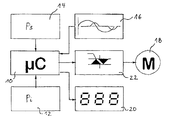
- the single figure shows a block diagram of a device according to the invention for air pressure-dependent speed control of a single-phase induction motor in ventilation devices.
- the device has a microcontroller 10, which is integrated in an internal control program or external memory module continuously processed.
- An energy supply not shown, is connected to the microcontroller 10 as well as an external clock.
- the microcontroller receives from an A / D converter, which is from one in one Not shown ventilation device arranged air pressure sensor determined values digitized, a current one at regular intervals Value.
- An actual air pressure value 12 detected by the microcontroller is replaced by a Air pressure setpoint 14 compared, which is also from the microcontroller 10th is recorded at regular intervals.
- the air pressure setpoint 14 can be set using a potentiometer, for example.
- the microcontroller 10 receives digitized from an intermediate amplifier 16 Signals of an AC voltage on which the single-phase induction motor is connected and a motor current that the single-phase induction motor 18 records. Each AC half wave is over detects a resistance, each of which has a voltage for half a wave falls off. Two inputs of the microcontroller are connected via an optocoupler accordingly alternately set to high signal or low signal, so that the AC voltage has a zero crossing just when the one input from high to low and the other input from low to high becomes, that is, when a change takes place.
- the zero crossing of the motor current can be determined in a similar way.
- the device also points for control purposes during commissioning a seven segment display 20 with which the one calculated by the control program RMS value of the motor voltage and the air pressure actual value 12 im Multiplex procedures are displayed. Commissioning of a ventilation device is additionally facilitated because the seven-segment display 20 instead of the air pressure actual value 12 indicates the air pressure setpoint 14 if the potentiometer for setting the air pressure setpoint is adjusted.
- the set air pressure setpoint 14 and the zero crossing of the AC voltage is from Control program via a PI control algorithm to zero crossing the ignition point related to the alternating voltage is determined for an ignition pulse, but only then via an optocoupler, not shown, and one Ignition amplifier on the control electrode of an electronic component 22, for example a triac, is transmitted when the microcontroller 10 detected motor current has a zero crossing or has decayed is.
- the triac switches the AC voltage to at the time of ignition Single-phase induction motor 18, which, depending on the working point, an inductive or ohmic motor current.
- the Triac 22 which falls short a certain motor current value back into the high-resistance State passes, gets after the calculated ignition timing another ignition pulse if the motor current is already at this point has subsided. Otherwise the ignition pulse is shifted until the control program a zero crossing of the motor current could be determined.
- the ignition pulse transmitted to the control electrode of the triac switches the Triac through so that the AC voltage on the single-phase induction motor 18th is present and a motor current can flow again.
- the ignition timing for the ignition pulse is specified so that the total power supplied to the single-phase induction motor 18 for increase or lowering and thus to adjust the actual air pressure value 12 to the air pressure setpoint 14 is sufficient.
- a correction of the control program determined ignition timing for the ignition pulse is during the Alignment of the actual value to the setpoint is easily possible because the Control program at fixed time intervals Values of the actual air pressure value 12 receives and calculates a new ignition timing.
- the difference between air pressure actual value 12 and air pressure setpoint 14 becomes corresponding larger or smaller, so that a new ignition timing for the ignition pulses is specified and an adjustment can take place.
- the control electrode of the triac After transmission of the ignition pulse generated by the microcontroller the control electrode of the triac is checked at certain time intervals, whether the transmitted ignition pulse is sufficient to switch the triac through was. If no motor current could be determined by the subroutine, an ignition pulse is again applied to the control electrode in the time interval transmitted until the triac switches through and a motor current from the subroutine is detected. Until the next zero crossing of the AC voltage no further ignition pulses are transmitted to the control electrode, so that despite the repetition of the ignition pulse it is ensured that the capacitive Working point of the single-phase induction motor 18 no undesirable Ignition pulses are generated.
- the ignition pulse is suppressed because an existing, slight inaccuracy in time when recognizing the zero crossing the AC voltage could lead to the ignition point for the Ignition pulse actually behind the zero crossing of the AC voltage lies and the subsequent AC half-wave thus unintentionally is switched through.
- the single-phase induction motor would accordingly take a motor current for half a wave, so that overall an unbalanced Current flow would be present.
- a microcontroller with appropriate wiring a microprocessor can be used so that the method can also be carried out is.
Landscapes
- Engineering & Computer Science (AREA)
- Power Engineering (AREA)
- Control Of Ac Motors In General (AREA)
Claims (7)
- Procédé pour réguler, en fonction d'une pression, la vitesse de rotation d'un moteur monophasé à induction (18) connecté à une tension alternative dans des dispositifs de ventilation ou similaires, une valeur effective de pression d'air (12) et une valeur de consigne de pression d'air (14) étant enregistrées et comparées entre elles par une micro-unité de commande (10), caractérisé en ce que les passages par zéro de la tension alternative et d'un courant de moteur sont enregistrés par la micro-unité de commande (10), et en ce qu'à partir de ces valeurs, au moyen d'un programme de commande visant à amener la valeur effective de pression d'air (12) au niveau de la valeur de consigne de pression d'air (14), est calculé un point d'amorçage qui influe sur la vitesse de rotation et se réfère à un passage par zéro de la tension alternative et qui est destiné à une impulsion d'amorçage transmise ensuite à un composant électronique (22) qui transmet la tension alternative au moteur monophasé à induction (18) lorsque le courant de moteur passe par zéro ou a décru.
- Procédé selon la revendication 1, caractérisé en ce que la production de l'impulsion d'amorçage est répétée jusqu'à ce qu'une conduction de courant soit constatée dans le moteur monophasé à induction (18).
- Procédé selon la revendication 1 ou 2, caractérisé en ce que, une fois l'amorçage du composant électronique (22) effectué, aucune impulsion d'amorçage n'est transmise jusqu'au prochain passage par zéro de la tension alternative.
- Procédé selon une des revendications précédentes, caractérisé en ce qu'une impulsion d'amorçage est neutralisée si le point d'amorçage défini par le programme de commande se trouve juste avant un passage par zéro de la tension alternative.
- Dispositif pour mettre en oeuvre le procédé selon la revendication 1, comprenant un moteur monophasé à induction (18), dont la vitesse de rotation peut être régulée en fonction d'une pression d'air dans un dispositif de ventilation, une micro-unité de commande (10) pour enregistrer la valeur de consigne de pression d'air (14) et la valeur effective de pression d'air (12) mesurée dans le dispositif de ventilation par un capteur de pression d'air, un circuit électrique (16) pour enregistrer et transmettre les valeurs de tension alternative et de courant de moteur à la micro-unité de commande (10), et un composant électronique (22) qui est mis en circuit pour transmettre la tension alternative à partir de la micro-unité de commande (10) à travers un coupleur optique et un amplificateur d'amorçage.
- Dispositif selon la revendication 5, caractérisé en ce que le composant électronique (22) destiné à transmettre la tension alternative est un triac.
- Dispositif selon l'une des revendications 5 ou 6, caractérisé en ce qu'il est prévu un moyen d'affichage à sept segments permettant d'afficher la valeur effective de la tension du moteur et la valeur effective de pression d'air (12) ou la valeur de consigne de pression d'air (14).
Priority Applications (3)
| Application Number | Priority Date | Filing Date | Title |
|---|---|---|---|
| DE59601224T DE59601224D1 (de) | 1996-04-26 | 1996-04-26 | Verfahren und Vorrichtung zur druckabhängigen Drehzahlsteuerung eines Einphasen-Induktionsmotors in Lüftungsvorrichtungen und dergleichen |
| AT96106603T ATE176364T1 (de) | 1996-04-26 | 1996-04-26 | Verfahren und vorrichtung zur druckabhängigen drehzahlsteuerung eines einphasen- induktionsmotors in lüftungsvorrichtungen und dergleichen |
| EP96106603A EP0803971B1 (fr) | 1996-04-26 | 1996-04-26 | Procédé et dispositif pour commander la vitesse de rotation d'un moteur monophasé à induction dans des dispositifs de ventilisation ou similaire en fonction de pression |
Applications Claiming Priority (1)
| Application Number | Priority Date | Filing Date | Title |
|---|---|---|---|
| EP96106603A EP0803971B1 (fr) | 1996-04-26 | 1996-04-26 | Procédé et dispositif pour commander la vitesse de rotation d'un moteur monophasé à induction dans des dispositifs de ventilisation ou similaire en fonction de pression |
Publications (2)
| Publication Number | Publication Date |
|---|---|
| EP0803971A1 EP0803971A1 (fr) | 1997-10-29 |
| EP0803971B1 true EP0803971B1 (fr) | 1999-01-27 |
Family
ID=8222718
Family Applications (1)
| Application Number | Title | Priority Date | Filing Date |
|---|---|---|---|
| EP96106603A Expired - Lifetime EP0803971B1 (fr) | 1996-04-26 | 1996-04-26 | Procédé et dispositif pour commander la vitesse de rotation d'un moteur monophasé à induction dans des dispositifs de ventilisation ou similaire en fonction de pression |
Country Status (3)
| Country | Link |
|---|---|
| EP (1) | EP0803971B1 (fr) |
| AT (1) | ATE176364T1 (fr) |
| DE (1) | DE59601224D1 (fr) |
Families Citing this family (2)
| Publication number | Priority date | Publication date | Assignee | Title |
|---|---|---|---|---|
| DE10317471B3 (de) * | 2003-04-16 | 2004-09-30 | Hanning Elektro-Werke Gmbh & Co. Kg | Verfahren zur Entlüftung eines Gebäudes, sowie Entlüftungsanlage für ein Gebäude |
| DE102007033491B4 (de) * | 2007-07-18 | 2019-10-17 | BSH Hausgeräte GmbH | Verfahren zum Betreiben eines Halbleiterstellers und Zündschaltung für einen schaltbaren Halbleitersteller |
Family Cites Families (6)
| Publication number | Priority date | Publication date | Assignee | Title |
|---|---|---|---|---|
| DE3419408A1 (de) * | 1984-05-24 | 1985-11-28 | AKO-Werke GmbH & Co KG, 7988 Wangen | Einrichtung zur drehzahlregelung |
| US4762463A (en) * | 1987-04-07 | 1988-08-09 | Yang Tai Her | Fan having speed indicator |
| JPS6414533A (en) * | 1987-07-06 | 1989-01-18 | Hitachi Ltd | Ventilation fan |
| US5200684A (en) * | 1988-04-18 | 1993-04-06 | Whirlpool Corporation | Electrical motor monitoring system for a domestic appliance |
| US4992709A (en) * | 1989-06-20 | 1991-02-12 | Lightolier, Inc. | Switching circuit providing adjustable capacitive series voltage dropping circuit with a fractional horsepower motor |
| US5418438A (en) * | 1993-02-26 | 1995-05-23 | General Electric Company | Draft inducer air flow control |
-
1996
- 1996-04-26 AT AT96106603T patent/ATE176364T1/de not_active IP Right Cessation
- 1996-04-26 EP EP96106603A patent/EP0803971B1/fr not_active Expired - Lifetime
- 1996-04-26 DE DE59601224T patent/DE59601224D1/de not_active Expired - Fee Related
Also Published As
| Publication number | Publication date |
|---|---|
| DE59601224D1 (de) | 1999-03-11 |
| EP0803971A1 (fr) | 1997-10-29 |
| ATE176364T1 (de) | 1999-02-15 |
Similar Documents
| Publication | Publication Date | Title |
|---|---|---|
| DE3934139C2 (de) | Elektronische Steuerschaltung für einen bürstenlosen Gleichstrommotor | |
| DE3706659C2 (fr) | ||
| EP2474089B1 (fr) | Procédé et circuiterie pour détecter la charge d'un moteur, sans capteur, et pour réguler l'intensité en fonction de la valeur de la charge dans des moteurs pas-à-pas | |
| DE69308521T2 (de) | Einphasen-Wechselstrommotor-Regelsystem | |
| DE69005883T2 (de) | Gerät zum Stoppen eines Motors und Verfahren zur Nutzung der Gegen-EMK. | |
| EP1191676B1 (fr) | Procédé de détection de la vitesse de rotation d'un moteur à courant alternatif et système de commande de moteur | |
| DE3202906A1 (de) | Verfahren und vorrichtung zur steuerung von wechselstrommotoren | |
| EP0876742B1 (fr) | Procede et circuit de commande electronique pour la regulation des caracteristiques de fonctionnement de lampes a decharge | |
| EP0859452B1 (fr) | Procédé et dispositif de contrÔle de puissance des consommateurs électriques connectés à un réseau d'alimentatin à tension alternative | |
| DE69633086T2 (de) | Geschwindigkeitsregelungsverfahren für einen elektrischen Motor | |
| EP0381789B1 (fr) | Méthode et appareil de régulation des graduateurs de courant alternatif monophasés ou prophylasés | |
| DE4031708C2 (de) | Verfahren zur Differenzdruckregelung eines von einem Einphasen-Kondensatormotor angetriebenen Pumpsystems und Schaltungsanordnung zur Durchführung des Verfahrens | |
| WO2008034670A1 (fr) | Procédé de fonctionnement d'un moteur électrique à commutation électronique | |
| EP0803971B1 (fr) | Procédé et dispositif pour commander la vitesse de rotation d'un moteur monophasé à induction dans des dispositifs de ventilisation ou similaire en fonction de pression | |
| EP1340988B1 (fr) | Méthode et appareil pour mesurer l'impedance dans un réseau d'alimentation électrique | |
| EP1675274A1 (fr) | Procédé de transmission de données sur une ligne de puissance à courant alternatif | |
| EP0458794B1 (fr) | Procede et dispositif pour commander des gradateurs de courant alternatif monophases ou polyphases | |
| DE10006648A1 (de) | Verfahren und Gerät zum Erfassen des Lastmoments und zum Bestimmen der Optimierung des Treiberstroms eines Motors | |
| DE4023954C2 (de) | Telemetrie-Empfänger mit Rauschsignalunterdrückung | |
| EP0948126B2 (fr) | Dispositif de détection de paramètre d'un moteur asynchrone | |
| EP1049243A2 (fr) | Méthode pour connecter un convertisseur avec un moteur asynchrone et convertisseur avec commande électric | |
| DE19734107A1 (de) | Dimmer | |
| DE112017007784T5 (de) | Motorantriebsanpassung | |
| EP0836269A1 (fr) | Dispositif de régulation de la vitesse d'un moteur à commutateur | |
| EP0706054B1 (fr) | Comparateur de phase |
Legal Events
| Date | Code | Title | Description |
|---|---|---|---|
| PUAI | Public reference made under article 153(3) epc to a published international application that has entered the european phase |
Free format text: ORIGINAL CODE: 0009012 |
|
| AK | Designated contracting states |
Kind code of ref document: A1 Designated state(s): AT CH DE LI |
|
| 17P | Request for examination filed |
Effective date: 19971126 |
|
| RBV | Designated contracting states (corrected) |
Designated state(s): AT CH DE LI |
|
| GRAG | Despatch of communication of intention to grant |
Free format text: ORIGINAL CODE: EPIDOS AGRA |
|
| GRAG | Despatch of communication of intention to grant |
Free format text: ORIGINAL CODE: EPIDOS AGRA |
|
| GRAH | Despatch of communication of intention to grant a patent |
Free format text: ORIGINAL CODE: EPIDOS IGRA |
|
| 17Q | First examination report despatched |
Effective date: 19980713 |
|
| GRAH | Despatch of communication of intention to grant a patent |
Free format text: ORIGINAL CODE: EPIDOS IGRA |
|
| GRAA | (expected) grant |
Free format text: ORIGINAL CODE: 0009210 |
|
| AK | Designated contracting states |
Kind code of ref document: B1 Designated state(s): AT CH DE LI |
|
| REF | Corresponds to: |
Ref document number: 176364 Country of ref document: AT Date of ref document: 19990215 Kind code of ref document: T |
|
| REG | Reference to a national code |
Ref country code: CH Ref legal event code: EP |
|
| REF | Corresponds to: |
Ref document number: 59601224 Country of ref document: DE Date of ref document: 19990311 |
|
| REG | Reference to a national code |
Ref country code: CH Ref legal event code: NV Representative=s name: PATENTANWAELTE SCHAAD, BALASS, MENZL & PARTNER AG |
|
| PLBE | No opposition filed within time limit |
Free format text: ORIGINAL CODE: 0009261 |
|
| STAA | Information on the status of an ep patent application or granted ep patent |
Free format text: STATUS: NO OPPOSITION FILED WITHIN TIME LIMIT |
|
| REG | Reference to a national code |
Ref country code: CH Ref legal event code: PFA Free format text: HANNING ELEKTRO-WERKE GMBH & CO. TRANSFER- HANNING ELEKTRO-WERKE GMBH & CO. KG |
|
| 26N | No opposition filed | ||
| PGFP | Annual fee paid to national office [announced via postgrant information from national office to epo] |
Ref country code: CH Payment date: 20040426 Year of fee payment: 9 |
|
| PG25 | Lapsed in a contracting state [announced via postgrant information from national office to epo] |
Ref country code: LI Free format text: LAPSE BECAUSE OF NON-PAYMENT OF DUE FEES Effective date: 20050430 Ref country code: CH Free format text: LAPSE BECAUSE OF NON-PAYMENT OF DUE FEES Effective date: 20050430 |
|
| REG | Reference to a national code |
Ref country code: CH Ref legal event code: PL |
|
| PGFP | Annual fee paid to national office [announced via postgrant information from national office to epo] |
Ref country code: AT Payment date: 20070423 Year of fee payment: 12 |
|
| PGFP | Annual fee paid to national office [announced via postgrant information from national office to epo] |
Ref country code: DE Payment date: 20070625 Year of fee payment: 12 |
|
| PG25 | Lapsed in a contracting state [announced via postgrant information from national office to epo] |
Ref country code: DE Free format text: LAPSE BECAUSE OF NON-PAYMENT OF DUE FEES Effective date: 20081101 |
|
| PG25 | Lapsed in a contracting state [announced via postgrant information from national office to epo] |
Ref country code: AT Free format text: LAPSE BECAUSE OF NON-PAYMENT OF DUE FEES Effective date: 20080426 |