EP0803920A2 - Rechargeable type small electric appliance - Google Patents
Rechargeable type small electric appliance Download PDFInfo
- Publication number
- EP0803920A2 EP0803920A2 EP97109643A EP97109643A EP0803920A2 EP 0803920 A2 EP0803920 A2 EP 0803920A2 EP 97109643 A EP97109643 A EP 97109643A EP 97109643 A EP97109643 A EP 97109643A EP 0803920 A2 EP0803920 A2 EP 0803920A2
- Authority
- EP
- European Patent Office
- Prior art keywords
- cover
- casing
- battery
- electric appliance
- rechargeable
- Prior art date
- Legal status (The legal status is an assumption and is not a legal conclusion. Google has not performed a legal analysis and makes no representation as to the accuracy of the status listed.)
- Granted
Links
- 238000003780 insertion Methods 0.000 claims description 3
- 230000037431 insertion Effects 0.000 claims description 3
- 239000000758 substrate Substances 0.000 claims 5
- 239000004020 conductor Substances 0.000 claims 2
- 230000010354 integration Effects 0.000 abstract 1
- 210000000078 claw Anatomy 0.000 description 13
- 230000002093 peripheral effect Effects 0.000 description 7
- 229910003307 Ni-Cd Inorganic materials 0.000 description 4
- 238000010276 construction Methods 0.000 description 4
- 230000004048 modification Effects 0.000 description 4
- 238000012986 modification Methods 0.000 description 4
- 230000000994 depressogenic effect Effects 0.000 description 3
- 238000010586 diagram Methods 0.000 description 2
- 230000005489 elastic deformation Effects 0.000 description 2
- 229910052793 cadmium Inorganic materials 0.000 description 1
- BDOSMKKIYDKNTQ-UHFFFAOYSA-N cadmium atom Chemical compound [Cd] BDOSMKKIYDKNTQ-UHFFFAOYSA-N 0.000 description 1
- OJIJEKBXJYRIBZ-UHFFFAOYSA-N cadmium nickel Chemical compound [Ni].[Cd] OJIJEKBXJYRIBZ-UHFFFAOYSA-N 0.000 description 1
- 238000003912 environmental pollution Methods 0.000 description 1
- 230000002265 prevention Effects 0.000 description 1
- 239000000126 substance Substances 0.000 description 1
Images


Classifications
-
- H—ELECTRICITY
- H05—ELECTRIC TECHNIQUES NOT OTHERWISE PROVIDED FOR
- H05K—PRINTED CIRCUITS; CASINGS OR CONSTRUCTIONAL DETAILS OF ELECTRIC APPARATUS; MANUFACTURE OF ASSEMBLAGES OF ELECTRICAL COMPONENTS
- H05K1/00—Printed circuits
- H05K1/18—Printed circuits structurally associated with non-printed electric components
-
- B—PERFORMING OPERATIONS; TRANSPORTING
- B26—HAND CUTTING TOOLS; CUTTING; SEVERING
- B26B—HAND-HELD CUTTING TOOLS NOT OTHERWISE PROVIDED FOR
- B26B19/00—Clippers or shavers operating with a plurality of cutting edges, e.g. hair clippers, dry shavers
- B26B19/28—Drive layout for hair clippers or dry shavers, e.g. providing for electromotive drive
- B26B19/286—Drive layout for hair clippers or dry shavers, e.g. providing for electromotive drive providing for two or more different electrical power sources
-
- B—PERFORMING OPERATIONS; TRANSPORTING
- B26—HAND CUTTING TOOLS; CUTTING; SEVERING
- B26B—HAND-HELD CUTTING TOOLS NOT OTHERWISE PROVIDED FOR
- B26B19/00—Clippers or shavers operating with a plurality of cutting edges, e.g. hair clippers, dry shavers
- B26B19/38—Details of, or accessories for, hair clippers, or dry shavers, e.g. housings, casings, grips, guards
- B26B19/3853—Housing or handle
-
- B—PERFORMING OPERATIONS; TRANSPORTING
- B26—HAND CUTTING TOOLS; CUTTING; SEVERING
- B26B—HAND-HELD CUTTING TOOLS NOT OTHERWISE PROVIDED FOR
- B26B19/00—Clippers or shavers operating with a plurality of cutting edges, e.g. hair clippers, dry shavers
- B26B19/38—Details of, or accessories for, hair clippers, or dry shavers, e.g. housings, casings, grips, guards
- B26B19/3873—Electric features; Charging; Computing devices
-
- H—ELECTRICITY
- H01—ELECTRIC ELEMENTS
- H01M—PROCESSES OR MEANS, e.g. BATTERIES, FOR THE DIRECT CONVERSION OF CHEMICAL ENERGY INTO ELECTRICAL ENERGY
- H01M10/00—Secondary cells; Manufacture thereof
- H01M10/42—Methods or arrangements for servicing or maintenance of secondary cells or secondary half-cells
- H01M10/46—Accumulators structurally combined with charging apparatus
-
- H—ELECTRICITY
- H01—ELECTRIC ELEMENTS
- H01M—PROCESSES OR MEANS, e.g. BATTERIES, FOR THE DIRECT CONVERSION OF CHEMICAL ENERGY INTO ELECTRICAL ENERGY
- H01M50/00—Constructional details or processes of manufacture of the non-active parts of electrochemical cells other than fuel cells, e.g. hybrid cells
- H01M50/20—Mountings; Secondary casings or frames; Racks, modules or packs; Suspension devices; Shock absorbers; Transport or carrying devices; Holders
- H01M50/204—Racks, modules or packs for multiple batteries or multiple cells
- H01M50/207—Racks, modules or packs for multiple batteries or multiple cells characterised by their shape
- H01M50/213—Racks, modules or packs for multiple batteries or multiple cells characterised by their shape adapted for cells having curved cross-section, e.g. round or elliptic
-
- H—ELECTRICITY
- H01—ELECTRIC ELEMENTS
- H01M—PROCESSES OR MEANS, e.g. BATTERIES, FOR THE DIRECT CONVERSION OF CHEMICAL ENERGY INTO ELECTRICAL ENERGY
- H01M50/00—Constructional details or processes of manufacture of the non-active parts of electrochemical cells other than fuel cells, e.g. hybrid cells
- H01M50/50—Current conducting connections for cells or batteries
-
- H—ELECTRICITY
- H05—ELECTRIC TECHNIQUES NOT OTHERWISE PROVIDED FOR
- H05K—PRINTED CIRCUITS; CASINGS OR CONSTRUCTIONAL DETAILS OF ELECTRIC APPARATUS; MANUFACTURE OF ASSEMBLAGES OF ELECTRICAL COMPONENTS
- H05K1/00—Printed circuits
- H05K1/02—Details
- H05K1/0286—Programmable, customizable or modifiable circuits
- H05K1/0293—Individual printed conductors which are adapted for modification, e.g. fusable or breakable conductors, printed switches
-
- H—ELECTRICITY
- H05—ELECTRIC TECHNIQUES NOT OTHERWISE PROVIDED FOR
- H05K—PRINTED CIRCUITS; CASINGS OR CONSTRUCTIONAL DETAILS OF ELECTRIC APPARATUS; MANUFACTURE OF ASSEMBLAGES OF ELECTRICAL COMPONENTS
- H05K1/00—Printed circuits
- H05K1/02—Details
- H05K1/11—Printed elements for providing electric connections to or between printed circuits
- H05K1/117—Pads along the edge of rigid circuit boards, e.g. for pluggable connectors
-
- H—ELECTRICITY
- H05—ELECTRIC TECHNIQUES NOT OTHERWISE PROVIDED FOR
- H05K—PRINTED CIRCUITS; CASINGS OR CONSTRUCTIONAL DETAILS OF ELECTRIC APPARATUS; MANUFACTURE OF ASSEMBLAGES OF ELECTRICAL COMPONENTS
- H05K1/00—Printed circuits
- H05K1/02—Details
- H05K1/0286—Programmable, customizable or modifiable circuits
- H05K1/0292—Programmable, customizable or modifiable circuits having a modifiable lay-out, i.e. adapted for engineering changes or repair
-
- H—ELECTRICITY
- H05—ELECTRIC TECHNIQUES NOT OTHERWISE PROVIDED FOR
- H05K—PRINTED CIRCUITS; CASINGS OR CONSTRUCTIONAL DETAILS OF ELECTRIC APPARATUS; MANUFACTURE OF ASSEMBLAGES OF ELECTRICAL COMPONENTS
- H05K2201/00—Indexing scheme relating to printed circuits covered by H05K1/00
- H05K2201/09—Shape and layout
- H05K2201/09009—Substrate related
- H05K2201/09063—Holes or slots in insulating substrate not used for electrical connections
-
- H—ELECTRICITY
- H05—ELECTRIC TECHNIQUES NOT OTHERWISE PROVIDED FOR
- H05K—PRINTED CIRCUITS; CASINGS OR CONSTRUCTIONAL DETAILS OF ELECTRIC APPARATUS; MANUFACTURE OF ASSEMBLAGES OF ELECTRICAL COMPONENTS
- H05K2201/00—Indexing scheme relating to printed circuits covered by H05K1/00
- H05K2201/09—Shape and layout
- H05K2201/09009—Substrate related
- H05K2201/09081—Tongue or tail integrated in planar structure, e.g. obtained by cutting from the planar structure
-
- H—ELECTRICITY
- H05—ELECTRIC TECHNIQUES NOT OTHERWISE PROVIDED FOR
- H05K—PRINTED CIRCUITS; CASINGS OR CONSTRUCTIONAL DETAILS OF ELECTRIC APPARATUS; MANUFACTURE OF ASSEMBLAGES OF ELECTRICAL COMPONENTS
- H05K2201/00—Indexing scheme relating to printed circuits covered by H05K1/00
- H05K2201/09—Shape and layout
- H05K2201/09009—Substrate related
- H05K2201/0909—Preformed cutting or breaking line
-
- H—ELECTRICITY
- H05—ELECTRIC TECHNIQUES NOT OTHERWISE PROVIDED FOR
- H05K—PRINTED CIRCUITS; CASINGS OR CONSTRUCTIONAL DETAILS OF ELECTRIC APPARATUS; MANUFACTURE OF ASSEMBLAGES OF ELECTRICAL COMPONENTS
- H05K2201/00—Indexing scheme relating to printed circuits covered by H05K1/00
- H05K2201/09—Shape and layout
- H05K2201/09009—Substrate related
- H05K2201/09127—PCB or component having an integral separable or breakable part
-
- H—ELECTRICITY
- H05—ELECTRIC TECHNIQUES NOT OTHERWISE PROVIDED FOR
- H05K—PRINTED CIRCUITS; CASINGS OR CONSTRUCTIONAL DETAILS OF ELECTRIC APPARATUS; MANUFACTURE OF ASSEMBLAGES OF ELECTRICAL COMPONENTS
- H05K2201/00—Indexing scheme relating to printed circuits covered by H05K1/00
- H05K2201/09—Shape and layout
- H05K2201/09209—Shape and layout details of conductors
- H05K2201/09372—Pads and lands
- H05K2201/094—Array of pads or lands differing from one another, e.g. in size, pitch or thickness; Using different connections on the pads
-
- H—ELECTRICITY
- H05—ELECTRIC TECHNIQUES NOT OTHERWISE PROVIDED FOR
- H05K—PRINTED CIRCUITS; CASINGS OR CONSTRUCTIONAL DETAILS OF ELECTRIC APPARATUS; MANUFACTURE OF ASSEMBLAGES OF ELECTRICAL COMPONENTS
- H05K2201/00—Indexing scheme relating to printed circuits covered by H05K1/00
- H05K2201/10—Details of components or other objects attached to or integrated in a printed circuit board
- H05K2201/10007—Types of components
- H05K2201/10037—Printed or non-printed battery
-
- H—ELECTRICITY
- H05—ELECTRIC TECHNIQUES NOT OTHERWISE PROVIDED FOR
- H05K—PRINTED CIRCUITS; CASINGS OR CONSTRUCTIONAL DETAILS OF ELECTRIC APPARATUS; MANUFACTURE OF ASSEMBLAGES OF ELECTRICAL COMPONENTS
- H05K2201/00—Indexing scheme relating to printed circuits covered by H05K1/00
- H05K2201/10—Details of components or other objects attached to or integrated in a printed circuit board
- H05K2201/10227—Other objects, e.g. metallic pieces
- H05K2201/10295—Metallic connector elements partly mounted in a hole of the PCB
-
- H—ELECTRICITY
- H05—ELECTRIC TECHNIQUES NOT OTHERWISE PROVIDED FOR
- H05K—PRINTED CIRCUITS; CASINGS OR CONSTRUCTIONAL DETAILS OF ELECTRIC APPARATUS; MANUFACTURE OF ASSEMBLAGES OF ELECTRICAL COMPONENTS
- H05K2201/00—Indexing scheme relating to printed circuits covered by H05K1/00
- H05K2201/10—Details of components or other objects attached to or integrated in a printed circuit board
- H05K2201/10431—Details of mounted components
- H05K2201/10606—Permanent holder for component or auxiliary printed circuits mounted on a printed circuit board [PCB]
-
- H—ELECTRICITY
- H05—ELECTRIC TECHNIQUES NOT OTHERWISE PROVIDED FOR
- H05K—PRINTED CIRCUITS; CASINGS OR CONSTRUCTIONAL DETAILS OF ELECTRIC APPARATUS; MANUFACTURE OF ASSEMBLAGES OF ELECTRICAL COMPONENTS
- H05K2201/00—Indexing scheme relating to printed circuits covered by H05K1/00
- H05K2201/10—Details of components or other objects attached to or integrated in a printed circuit board
- H05K2201/10613—Details of electrical connections of non-printed components, e.g. special leads
- H05K2201/10621—Components characterised by their electrical contacts
- H05K2201/10689—Leaded Integrated Circuit [IC] package, e.g. dual-in-line [DIL]
-
- H—ELECTRICITY
- H05—ELECTRIC TECHNIQUES NOT OTHERWISE PROVIDED FOR
- H05K—PRINTED CIRCUITS; CASINGS OR CONSTRUCTIONAL DETAILS OF ELECTRIC APPARATUS; MANUFACTURE OF ASSEMBLAGES OF ELECTRICAL COMPONENTS
- H05K2201/00—Indexing scheme relating to printed circuits covered by H05K1/00
- H05K2201/20—Details of printed circuits not provided for in H05K2201/01 - H05K2201/10
- H05K2201/2036—Permanent spacer or stand-off in a printed circuit or printed circuit assembly
-
- H—ELECTRICITY
- H05—ELECTRIC TECHNIQUES NOT OTHERWISE PROVIDED FOR
- H05K—PRINTED CIRCUITS; CASINGS OR CONSTRUCTIONAL DETAILS OF ELECTRIC APPARATUS; MANUFACTURE OF ASSEMBLAGES OF ELECTRICAL COMPONENTS
- H05K2203/00—Indexing scheme relating to apparatus or processes for manufacturing printed circuits covered by H05K3/00
- H05K2203/17—Post-manufacturing processes
- H05K2203/175—Configurations of connections suitable for easy deletion, e.g. modifiable circuits or temporary conductors for electroplating; Processes for deleting connections
-
- H—ELECTRICITY
- H05—ELECTRIC TECHNIQUES NOT OTHERWISE PROVIDED FOR
- H05K—PRINTED CIRCUITS; CASINGS OR CONSTRUCTIONAL DETAILS OF ELECTRIC APPARATUS; MANUFACTURE OF ASSEMBLAGES OF ELECTRICAL COMPONENTS
- H05K2203/00—Indexing scheme relating to apparatus or processes for manufacturing printed circuits covered by H05K3/00
- H05K2203/17—Post-manufacturing processes
- H05K2203/176—Removing, replacing or disconnecting component; Easily removable component
-
- H—ELECTRICITY
- H05—ELECTRIC TECHNIQUES NOT OTHERWISE PROVIDED FOR
- H05K—PRINTED CIRCUITS; CASINGS OR CONSTRUCTIONAL DETAILS OF ELECTRIC APPARATUS; MANUFACTURE OF ASSEMBLAGES OF ELECTRICAL COMPONENTS
- H05K3/00—Apparatus or processes for manufacturing printed circuits
- H05K3/30—Assembling printed circuits with electric components, e.g. with resistor
- H05K3/32—Assembling printed circuits with electric components, e.g. with resistor electrically connecting electric components or wires to printed circuits
- H05K3/34—Assembling printed circuits with electric components, e.g. with resistor electrically connecting electric components or wires to printed circuits by soldering
- H05K3/3447—Lead-in-hole components
-
- Y—GENERAL TAGGING OF NEW TECHNOLOGICAL DEVELOPMENTS; GENERAL TAGGING OF CROSS-SECTIONAL TECHNOLOGIES SPANNING OVER SEVERAL SECTIONS OF THE IPC; TECHNICAL SUBJECTS COVERED BY FORMER USPC CROSS-REFERENCE ART COLLECTIONS [XRACs] AND DIGESTS
- Y02—TECHNOLOGIES OR APPLICATIONS FOR MITIGATION OR ADAPTATION AGAINST CLIMATE CHANGE
- Y02E—REDUCTION OF GREENHOUSE GAS [GHG] EMISSIONS, RELATED TO ENERGY GENERATION, TRANSMISSION OR DISTRIBUTION
- Y02E60/00—Enabling technologies; Technologies with a potential or indirect contribution to GHG emissions mitigation
- Y02E60/10—Energy storage using batteries
Definitions
- the present invention generally relates to electric appliances and more particularly, to a small electric appliance incorporating a rechargeable battery, in which the rechargeable battery is removable therefrom.
- rechargeable batteries which can be used repetitively, are mainly employed in place of dry cells.
- rechargeable batteries for example, Ni-Cd (nickel-cadmium) batteries contain harmful substances such as cadmium. Therefore, from a standpoint of prevention of environmental pollution, it is not desirable to discard the Ni-Cd batteries together with the electric appliances anywhere. Thus, when the electric appliances incorporating the Ni-Cd batteries are discarded, the Ni-Cd batteries are required to be removed from the electric appliances so as to be collected for their safe disposal.
- the known electric appliances have a risk that if an operator inadvertently removes the rechargeable battery from the known electric appliances when the rechargeable battery is being charged by connecting the rechargeable battery to an external power source, the operator may receive an electric shock.
- An object of the present invention is to provide a rechargeable type small electric appliance in which a safety countermeasure is taken such that electric current is not applied to a load side of the electric appliance even if charging of the electric appliance is performed inadvertently after the rechargeable battery has been removed from the electric appliance.
- the present invention therefore provides a rechargeable type small electric appliance as set out in claim 1, claim 8 or claim 11.
- a chargeable type electric shaver being a rechargeable type small electric appliance to which the present invention may be applied is described with reference to the accompanying figures.
- Figs. 1 to 3 show a rechargeable type electric shaver K22 according to a 1st embodiment of the present invention.
- the shaving blade unit 2 is provided at the upper portion of the casing 1, while the charging plug 3 is provided at the bottom portion of the casing 1.
- the charging plug 3 has a pair of retractable plug blades 105.
- the plug blades 105 retractably project from a pair of slits 106 formed on the side face 1A of the casing 1, respectively.
- the battery outlet 13 opens at the side face 1A, the front face 1B and a rear face 1C.
- the pattern 18 corresponding to a circuit shown in Fig. 3 is formed on the wiring board 4.
- the rechargeable battery 5, the transformer 6, a switch 111, etc. are mounted on the wiring board 4. At least the rechargeable battery 5 is so provided on the wiring board 4 as to confront the battery outlet 13.
- the rechargeable battery 5 is detachably mounted on the wiring board 4.
- the lid 14 having an U-shaped cross section is detachably mounted on the battery outlet 13 so as to be opened in the direction of the arrow Q identical with the direction of projection of the plug blades 105.
- the lid 14 has a nonslip portion 110 for preventing slip of a finger and a predetermined number of engageable claws 118 capable of elastic deformation. Through utilization of elasticity, the engageable claws 118 are detachably engageable with a mouth edge of the battery outlet 13 of the casing 1.
- the engageable claws 118 are brought into engagement with the mouth edge of the battery outlet 13 such that the battery outlet 13 is kept closed by the lid 14. Meanwhile, when the lid 14 is pulled in the direction of the arrow Q by gripping the nonslip portion 110 with a hand, the engageable claws 118 are disengaged from the mouth edge of the battery outlet 13 and thus, the lid 14 is removed from the casing 1. Meanwhile, the window 84 is provided on the lid 14 so as to enable the operator to visually inspect presence of the rechargeable battery 5 from outside of the lid 14.
- the plug blades 105 are projected as shown in Fig. 1 and are inserted into a socket outlet 120 on a wall or a socket outlet provided at one end of a power source cord.
- the socket outlet 120 is disposed adjacent to the lid 14 in the direction of the arrow Q for opening the lid 14 and thus, the socket outlet 120 prevents the lid 14 from being removed from the casing 1. Therefore, the rechargeable battery 5 is not removed from the wiring board 4 inadvertently at the time of charging of the electric shaver K22, thereby resulting in safe charging of the electric shaver K22.
- the lid 14 can be removed from the casing 1, so that the rechargeable battery 5 can be removed from the wiring board 4 by snapping off the peripheral portions 4b from the wiring board 4.
- the plug blades 105 of the charging plug 3 are retractably displaced by sliding a knob of the charging plug 3 in the direction of the arrow Q and in the direction opposite to the direction of the arrow Q but may also be retractably displaced through their rotational operation.
- Figs. 4 and 5 show a rechargeable type electric shaver K23 according to a 2nd embodiment of the present invention.
- the battery outlet 13 is provided at the bottom of the casing 1.
- the peripheral portions 4b project from the wiring board 4 towards the battery outlet 13 so as to be snapped off from the wiring board 4 and the rechargeable battery 5 is mounted on the peripheral portions 4b.
- the charging pins 28 mounted on the wiring board 4 project towards the battery outlet 13.
- the lid 14 is detachably mounted on the battery outlet 13.
- the lid 14 has a plug inlet 124 for receiving a plug 123 of the power source cord 52 and the window 84 for visually inspecting presence of the rechargeable battery 5.
- the engageable claws 118 capable of elastic deformation are provided on the lid 14 and are detachably engaged with the mouth edge of the battery outlet 13 such that the battery outlet 13 is kept closed by the lid 14.
- the charging pins 28 are projected into the plug inlet 124.
- the lid 14 can be removed from the casing 1 and thus, the rechargeable battery 5 can be removed from the wiring board 4.
- Fig. 6 shows a rechargeable type electric shaver K24 according to a 3rd embodiment of the present invention.
- the electric shaver K24 is generally similar to the electric shaver K23, but differs in that in the electric shave K24, the lid 14 is provided with the charging plug 3 having the retractable plug blades.
- the lid 14 can be removed from the casing 1 such that the rechargeable battery 14 can be removed from the wiring board 4.
- Fig. 7 shows a rechargeable type electric shaver K25 according to a 4th embodiment of the present invention.
- the electric shaver K25 is fundamentally the same as the electric shaver K23.
- the charging pins 28 are provided on the casing 1.
- the charging pins 28 are provided in the plug inlet 124 of the lid 14 such that one end of each of the charging pins 28 is inserted into each of pin holes 131 of the wiring board 4 when the lid 14 is mounted on the battery outlet 13.
- Figs. 8a, 8b, and 8c show a rechargeable type electric shaver K26 according to a 5th embodiment of the present invention.
- the battery outlet 13 is formed at one side face of the casing 1 and the plug inlet 124 is formed at the bottom face of the casing 1.
- the lid 14 is detachably mounted on the battery outlet 13.
- a lid locking means is provided between the lid 14 and the plug inlet 124. When the plug 123 of the power source cord 52 is inserted into the plug inlet 124, the lid locking means locks the lid 14 so as to prevent the lid 14 from being removed from the casing 1. Meanwhile, when the plug 123 has been drawn from the plug inlet 124, the lid locking means allows the lid 14 to be removed from the casing 1.
- the lid locking means includes a guide groove 125 formed, between the battery outlet 13 and the plug inlet 124, on the casing 1 and a first lock piece 126 having an L-shaped cross section.
- the first lock piece 126 is vertically movably incorporated in the guide groove 125.
- One end 126a of the first lock piece 126 is projected into the plug inlet 124.
- the other end 126b of the first lock means 126 is projected into the battery outlet 13 so as be brought into engagement with a recess 127 of the lid 14.
- the charging preventing means includes a guide groove 128 formed, between the battery outlet 13 and the plug inlet 124, on the casing 1 and a second lock piece 129 having an L-shaped cross section.
- the second lock piece 129 is horizontally slidably incorporated in the guide groove 128 through a spring 130 such that one end 129a of the second lock piece 129 closes or opens, upon horizontal slide of the second lock piece 129, an upper end opening of the guide groove 125 confronting the battery outlet 13.
- Figs. 9a , 9b and 9c show a rechargeable type electric shaver K27 according to a 6th embodiment of the present invention.
- the electric shaver K27 is a modification of the electric shaver K26.
- the first lock piece 126 is incorporated between the battery outlet 13 and the plug inlet 124 of the casing 1 in the same manner as the electric shaver K26.
- the electric shaver K27 is different, in construction of the charging preventing means, from the electric shaver K26.
- the second lock piece 129 has a substantially U-shaped cross section and is horizontally slidably incorporated, through the spring 130, in the guide groove 128 formed between the battery outlet 13 and the plug inlet 124 of the casing 1. Furthermore, the ends 129a and 129b of the second lock piece 129 are arranged to retractably project into the battery outlet 13 and the plug inlet 124, respectively.
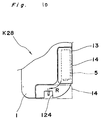
- Fig.10 shows a rechargeable type electric shaver K28 according to a 7th embodiment of the present invention.
- the battery outlet 13 is formed at the side face of the casing 1
- the plug inlet 124 is formed at the bottom face of the casing 1.
- the lid 14 cannot be returned to the original position in the direction opposite to the direction of the arrow R. Therefore, when the battery outlet 13 is opened and the plug inlet 124 is closed by the lid 14 by sliding the lid 14 towards the plug inlet 124, the rechargeable battery 5 can be removed from the wiring board 4 but such an undesirable phenomenon does not take place that the operator receives an electric shock through inadvertent charging of the electric shaver K28. It is needless to say that the slits 106 for the plug blades 105 of the charging plug 3 in the electric shaver K22 may also be closed by the lid 14 in place of the plug inlet 124.
- the rechargeable battery 5 is directly mounted on the wiring board 4 but may also be gripped between ribs projecting from the inner face of the casing 1 in a known manner.
- the rechargeable battery 5 can be easily taken out of the battery outlet 13 by opening the lid 14 and removing the rechargeable battery 5 from the wiring board 4 without unreasonably destroying the casing 1 at random. Furthermore, since the lid 14 cannot be removed from the battery outlet 13 at the time of charging of the electric appliance, such an accident can be prevented that the operator receives an electric shock by taking the rechargeable battery 5 out of the casing 1 while the electric appliance is being connected to the external power source, thereby resulting in safe removal of the electric appliance.
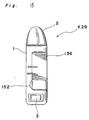
- Figs. 11 to 15 show a rechargeable type electric shaver K29 according to a 8th embodiment of the present invention.
- the electric shaver K29 includes the shaving blade unit 2 provided at the upper portion of the casing 1 and the charging plug 3 provided at the bottom portion of the casing 1.
- the battery outlet 13 opens at the side face and the front or rear face of the casing 1.
- the lid 14 is formed by a switch operating button 136 itself having an L-shaped cross section.
- the lid 14 is vertically slidably mounted on the battery outlet 13 so as to be displaced between an ON position (Fig. 13) for turning on a switch 141 and an OFF position (Figs. 12 and 14 ) for turning off the switch 141.
- a pattern corresponding to a circuit shown in Fig. 15, the rechargeable battery 5, the transformer 6, the switch 141, etc. are mounted on the wiring board 4. At least the rechargeable battery 5 and the switch 141 are so mounted on the wiring board 4 as to confront the battery outlet 13.
- An actuator 148 of the switch 141 is gripped between a pair of lips 147 formed on the inner face of the lid 14 such that the lips 147 turns on and off the actuator 148 when the lid 14 has been slid to the ON and OFF positions, respectively.
- a lid control means for controlling removal of the lid 14 is provided between the lid 14 and the casing 1.
- the lid control means functions to prevent removal of the lid 14 at the ON position but allow removal of the lid 14 at the OFF position.
- at least one pair of the engageable claws 118 are provided on the inner face of the lid 14.
- a pair of wall pieces 150 engageable with the engageable claws 118, respectively are formed in the battery outlet 13.
- the engageable claws 118 are held in engagement with the wall pieces 150 so as to allow the lid 14 to slide vertically between the ON position and the OFF position.
- the engageable claws 118 can be disengaged from the wall pieces 150.
- a cutout 152 for removing the lid 14 is provided at a lower portion of the battery outlet 13 as shown in Figs. 12 and 14 .
- a coin 153 or the like is inserted into the cutout 152 and then, the lid 14 is pried in the direction of the arrow T by the coin 153, the engageable claws 118 are disengaged from the wall pieces 150 such that the lid 14 is removed from the casing 1.
- the lid 14 cannot be pried by the coin 153 as shown in Fig. 13 even if the coin 153 is inserted into the cutout 152, the lid 14 cannot be removed from the casing 1.
- the lid 14 In order to take the rechargeable battery 5 out of the electric appliance K29, the lid 14 is slid to the OFF position as shown in Figs. 12 and 14 . Subsequently, after the switch 141 has been turned off, the coin 153 is inserted into the cutout 152 and then, the lid 14 is pried by the coin 153 such that the lid 14 is removed from the casing 1 as described above. Thus, by snapping off the peripheral portions 4b from the wiring board 4 along the snap line 33, the rechargeable battery 5 can be taken out of the battery outlet 13. Since the switch 141 is turned off at this time, the peripheral portions 4b can be snapped off from the wiring board 4 safely without such a risk as generation of sparks.
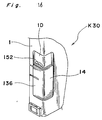
- Fig. 16 shows a rechargeable type electric shaver K30 according to a 9th embodiment of the present invention.
- the electric shaver K30 is a modification of the electric shaver K29 in connection with position of the cutout 152.
- the casing 1 has a wall face 1D in sliding contact with the inner face of the lid 14 and the cutout 152 is formed at a portion of the wall face 1D.
- the cutout 152 is completely covered by the lid 14 when the lid 14 is at the ON position. Meanwhile, when the lid 14 has been slid to the OFF position, the cutout 152 is exposed by the lid 14 such that the lid 14 can be pried by the coin 153 inserted into the cutout 152. Since other constructions of the electric shaver K30 are similar to those of the electric shaver K29, description thereof is abbreviated for the sake of brevity.
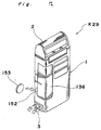
- Fig. 17 shows a rechargeable battery K31 according to a 10th embodiment of the present invention.
- the electric shaver K31 is different, in actuation mode of the switch 141 and construction of the lid 14, from the electric shaver K29.
- the switch operating button 136 is of push type and the lid 14 is formed by a holder plate 156 for holding the switch operating button 136 together with the switch 141.
- the lid control means provided between the lid 14 and the casing 1 includes a pair of the engageable claws 118 projecting from a box of the switch 141 and a retainer hole 155 formed on each of a pair of support pieces 154 projecting in the battery outlet 13 of the casing 1.
- the engageable claws 118 are, respectively, brought into engagement with the retainer holes 155 such that the battery outlet 13 is kept closed by the lid 14.
- the rechargeable battery 5 can be efficiently taken out of the battery outlet 13 by opening the lid 14 and removing the rechargeable battery 5 from the wiring board 4 without unreasonably destroying the casing 1 at random. Furthermore, since the lid 14 cannot be removed from the casing 1 before the switch 141 is turned off, the rechargeable battery 5 can be taken out of the casing 1 safely without generation of sparks even when the rechargeable battery 5 whose electric power has not yet been consumed completely is taken out of the casing 1.
Landscapes
- Engineering & Computer Science (AREA)
- Microelectronics & Electronic Packaging (AREA)
- Chemical & Material Sciences (AREA)
- Chemical Kinetics & Catalysis (AREA)
- Electrochemistry (AREA)
- General Chemical & Material Sciences (AREA)
- Life Sciences & Earth Sciences (AREA)
- Forests & Forestry (AREA)
- Mechanical Engineering (AREA)
- Manufacturing & Machinery (AREA)
- Secondary Cells (AREA)
- Battery Mounting, Suspending (AREA)
- Charge And Discharge Circuits For Batteries Or The Like (AREA)
Abstract
Description
- The present invention generally relates to electric appliances and more particularly, to a small electric appliance incorporating a rechargeable battery, in which the rechargeable battery is removable therefrom.
- Of recent years, in small electric appliances such as an electric shaver, etc., rechargeable batteries, which can be used repetitively, are mainly employed in place of dry cells. However, rechargeable batteries, for example, Ni-Cd (nickel-cadmium) batteries contain harmful substances such as cadmium. Therefore, from a standpoint of prevention of environmental pollution, it is not desirable to discard the Ni-Cd batteries together with the electric appliances anywhere. Thus, when the electric appliances incorporating the Ni-Cd batteries are discarded, the Ni-Cd batteries are required to be removed from the electric appliances so as to be collected for their safe disposal.
- The known electric appliances have a risk that if an operator inadvertently removes the rechargeable battery from the known electric appliances when the rechargeable battery is being charged by connecting the rechargeable battery to an external power source, the operator may receive an electric shock.
- Furthermore, in the known electric appliances, if the rechargeable battery is removed from the known electric appliances by cutting the lead wires when not only electric power of the rechargeable battery has not yet vanished but a power source switch of the known electric appliances is in an ON state, there is such a danger as generation of sparks from cut portions of the lead wires.
- An object of the present invention is to provide a rechargeable type small electric appliance in which a safety countermeasure is taken such that electric current is not applied to a load side of the electric appliance even if charging of the electric appliance is performed inadvertently after the rechargeable battery has been removed from the electric appliance.
- The present invention therefore provides a rechargeable type small electric appliance as set out in
claim 1,claim 8 or claim 11. - Embodiments of the present invention will now be described by way of example with reference to the accompanying drawings, in which:
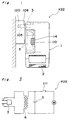
- Fig. 1 is a side elevational view showing a chargeable state of a rechargeable type small electric appliance according to a 1st embodiment of the present invention;
- Fig. 2 is a perspective view showing a state in which a lid has been removed from the electric appliance of Fig. 1;
- Fig. 3 is a circuit diagram of the electric appliance of Fig. 1;
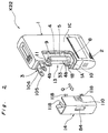
- Fig. 4 is a front elevational view of a rechargeable type small electric appliance according to a 2nd embodiment of the present invention;
- Fig. 5 is a perspective view showing a state in which a lid has been removed from the electric appliance of Fig. 4;
- Figs. 6 and 7 are views similar to Fig. 57, particularly showing 3rd and 4th embodiments of the present invention, respectively;
- Figs. 8a and 8b are fragmentary front elevational views showing a nonchargeable state and a chargeable state of a rechargeable type small electric appliance according to a 5th embodiment of the present invention, respectively;
- Fig. 8c is a fragmentary front elevational view showing a state in which a lid has been removed from the electric appliance of Fig. 8a;
- Figs. 9a, 9b and 9c are views similar to Figs. 8a, 8b and 8c, respectively, particularly showing a 6th embodiment of the present invention;
- Fig. 10 is a fragmentary front elevational view of a rechargeable type small electric appliance according to a 7th embodiment of the present invention;
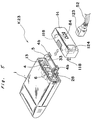
- Fig. 11 is a fragmentary perspective view showing a state in which a lid has been removed from a rechargeable type small electric appliance according to a 8th embodiment of the present invention;
- Fig. 12 is a perspective view of the electric appliance of Fig. 11;
- Fig. 13 is a side elevational view of the electric appliance of Fig. 11;
- Fig. 14 is a partially sectional top plan view of the electric appliance of Fig. 11;
- Fig. 15 is a circuit diagram of the electric appliance of Fig. 11;
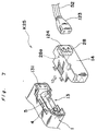
- Fig. 16 is a fragmentary perspective view of a rechargeable type small electric appliance according to a 9th embodiment of the present invention; and
- Fig. 17 is a perspective view showing a state in which a lid has been removed from a rechargeable type small electric appliance according to a 10th embodiment of the present invention.
- Before the description of the present invention proceeds, it is to be noted that like parts are designated by like reference numerals throughout several views of the accompanying drawings.
- A chargeable type electric shaver being a rechargeable type small electric appliance to which the present invention may be applied is described with reference to the accompanying figures.
- Figs. 1 to 3 show a rechargeable type electric shaver K22 according to a 1st embodiment of the present invention. The
shaving blade unit 2 is provided at the upper portion of thecasing 1, while thecharging plug 3 is provided at the bottom portion of thecasing 1. Thecharging plug 3 has a pair ofretractable plug blades 105. Theplug blades 105 retractably project from a pair ofslits 106 formed on theside face 1A of thecasing 1, respectively. In the vicinity of theslits 106, thebattery outlet 13 opens at theside face 1A, thefront face 1B and a rear face 1C. Thepattern 18 corresponding to a circuit shown in Fig. 3 is formed on thewiring board 4. Furthermore, therechargeable battery 5, thetransformer 6, a switch 111, etc. are mounted on thewiring board 4. At least therechargeable battery 5 is so provided on thewiring board 4 as to confront thebattery outlet 13. - The
rechargeable battery 5 is detachably mounted on thewiring board 4. For example, theperipheral portions 4b of the joints between thenegative terminal 8 and thelead piece 10 and between thepositive terminal 9 and thelead piece 11 are snapped off from thewiring board 4 along thesnap line 33. Thelid 14 having an U-shaped cross section is detachably mounted on thebattery outlet 13 so as to be opened in the direction of the arrow Q identical with the direction of projection of theplug blades 105. Thelid 14 has anonslip portion 110 for preventing slip of a finger and a predetermined number ofengageable claws 118 capable of elastic deformation. Through utilization of elasticity, theengageable claws 118 are detachably engageable with a mouth edge of thebattery outlet 13 of thecasing 1. Theengageable claws 118 are brought into engagement with the mouth edge of thebattery outlet 13 such that thebattery outlet 13 is kept closed by thelid 14. Meanwhile, when thelid 14 is pulled in the direction of the arrow Q by gripping thenonslip portion 110 with a hand, theengageable claws 118 are disengaged from the mouth edge of thebattery outlet 13 and thus, thelid 14 is removed from thecasing 1. Meanwhile, thewindow 84 is provided on thelid 14 so as to enable the operator to visually inspect presence of therechargeable battery 5 from outside of thelid 14. - When the electric shaver K22 is charged, the
plug blades 105 are projected as shown in Fig. 1 and are inserted into asocket outlet 120 on a wall or a socket outlet provided at one end of a power source cord. In this charging state, thesocket outlet 120 is disposed adjacent to thelid 14 in the direction of the arrow Q for opening thelid 14 and thus, thesocket outlet 120 prevents thelid 14 from being removed from thecasing 1. Therefore, therechargeable battery 5 is not removed from thewiring board 4 inadvertently at the time of charging of the electric shaver K22, thereby resulting in safe charging of the electric shaver K22. On the contrary, when the electric shaver K22 is not being charged, thelid 14 can be removed from thecasing 1, so that therechargeable battery 5 can be removed from thewiring board 4 by snapping off theperipheral portions 4b from thewiring board 4. - The
plug blades 105 of thecharging plug 3 are retractably displaced by sliding a knob of thecharging plug 3 in the direction of the arrow Q and in the direction opposite to the direction of the arrow Q but may also be retractably displaced through their rotational operation. - Figs. 4 and 5 show a rechargeable type electric shaver K23 according to a 2nd embodiment of the present invention. In the electric shaver K23, the
battery outlet 13 is provided at the bottom of thecasing 1. Theperipheral portions 4b project from thewiring board 4 towards thebattery outlet 13 so as to be snapped off from thewiring board 4 and therechargeable battery 5 is mounted on theperipheral portions 4b. Meanwhile, thecharging pins 28 mounted on thewiring board 4 project towards thebattery outlet 13. Thelid 14 is detachably mounted on thebattery outlet 13. Thelid 14 has aplug inlet 124 for receiving aplug 123 of thepower source cord 52 and thewindow 84 for visually inspecting presence of therechargeable battery 5. Furthermore, theengageable claws 118 capable of elastic deformation are provided on thelid 14 and are detachably engaged with the mouth edge of thebattery outlet 13 such that thebattery outlet 13 is kept closed by thelid 14. When thebattery outlet 13 is being closed by thelid 14, thecharging pins 28 are projected into theplug inlet 124. - By the above described arrangement of the electric shaver K23, when the
plug 123 of thepower source cord 52 is inserted into theplug inlet 124, thecharging pins 28 are fitted into theplug 123 and thus, theplug 123 prevents thelid 14 from being removed from thecasing 1. Hence, at this time, therechargeable battery 5 cannot be removed from thewiring board 4, so that it is not possible for the operator to receive an electric shock. - On the other hand, when the
plug 123 has been drawn from theplug inlet 124, thelid 14 can be removed from thecasing 1 and thus, therechargeable battery 5 can be removed from thewiring board 4. - Fig. 6 shows a rechargeable type electric shaver K24 according to a 3rd embodiment of the present invention. The electric shaver K24 is generally similar to the electric shaver K23, but differs in that in the electric shave K24, the
lid 14 is provided with the chargingplug 3 having the retractable plug blades. - By this arrangement of the electric shaver K24, since the charging
plug 3 is inserted into thesocket outlet 120 at the time of charging of the electric shaver K24 in the same manner as the electric shaver K22, thelid 14 cannot be removed from thecasing 1 and thus, the rechargeable battery is not removed from thewiring board 4 inadvertently. - On the contrary, when the electric shaver K24 is not being charged, the
lid 14 can be removed from thecasing 1 such that therechargeable battery 14 can be removed from thewiring board 4. - Fig. 7 shows a rechargeable type electric shaver K25 according to a 4th embodiment of the present invention. The electric shaver K25 is fundamentally the same as the electric shaver K23. In the electric shaver K23, the charging pins 28 are provided on the
casing 1. On the other hand, in the electric shaver K25, the charging pins 28 are provided in theplug inlet 124 of thelid 14 such that one end of each of the charging pins 28 is inserted into each of pin holes 131 of thewiring board 4 when thelid 14 is mounted on thebattery outlet 13. - Figs. 8a, 8b, and 8c show a rechargeable type electric shaver K26 according to a 5th embodiment of the present invention. In the electric shaver K26, the
battery outlet 13 is formed at one side face of thecasing 1 and theplug inlet 124 is formed at the bottom face of thecasing 1. Thelid 14 is detachably mounted on thebattery outlet 13. A lid locking means is provided between thelid 14 and theplug inlet 124. When theplug 123 of thepower source cord 52 is inserted into theplug inlet 124, the lid locking means locks thelid 14 so as to prevent thelid 14 from being removed from thecasing 1. Meanwhile, when theplug 123 has been drawn from theplug inlet 124, the lid locking means allows thelid 14 to be removed from thecasing 1. - The lid locking means includes a
guide groove 125 formed, between thebattery outlet 13 and theplug inlet 124, on thecasing 1 and afirst lock piece 126 having an L-shaped cross section. Thefirst lock piece 126 is vertically movably incorporated in theguide groove 125. Oneend 126a of thefirst lock piece 126 is projected into theplug inlet 124. Meanwhile, as shown in Fig. 8b , only when the first lock means 126 has been lifted, theother end 126b of the first lock means 126 is projected into thebattery outlet 13 so as be brought into engagement with arecess 127 of thelid 14. - Furthermore, there is provided a charging preventing means for preventing the
plug 123 from being inserted into theplug inlet 124 when thelid 14 has been removed from thecasing 1. The charging preventing means includes aguide groove 128 formed, between thebattery outlet 13 and theplug inlet 124, on thecasing 1 and asecond lock piece 129 having an L-shaped cross section. Thesecond lock piece 129 is horizontally slidably incorporated in theguide groove 128 through aspring 130 such that oneend 129a of thesecond lock piece 129 closes or opens, upon horizontal slide of thesecond lock piece 129, an upper end opening of theguide groove 125 confronting thebattery outlet 13. - Therefore, as shown in Fig. 8a , when the
plug 123 of thepower source cord 52 is not being inserted into theplug inlet 124, namely when the electric shaver K26 is not being charged, thefirst lock piece 126 descends in theguide groove 125 by its own weight or by a downward urging force of a spring and thesecond lock piece 129 is depressed into theguide groove 128 against an urging force of thespring 130 by thelid 14. Thus, at this time, thelid 14 can be removed from thebattery outlet 13. - However, when the
plug 123 of thepower source cord 52 has been inserted into theplug inlet 124 as shown in Fig. 8b , thefirst lock piece 126 is lifted by theplug 123 so as to bring theother end 126b of thefirst lock piece 126 into engagement with therecess 127 of thelid 14. Hence, thelid 14 cannot be removed from thebattery outlet 13. - When the
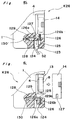
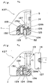
lid 14 has been removed from thebattery outlet 13 in the state of Fig. 8a in order to take therechargeable battery 5 out of thecasing 1, thesecond lock piece 129 is projected into thebattery outlet 13 by the urging force of thespring 130 as shown in Fig. 8c so as to close theguide groove 125 such that ascent of thefirst lock piece 126 is prevented. Therefore, at this time, even if the operator tries to insert theplug 123 of thepower source cord 52 into theplug inlet 124, theend 126a of thefirst lock piece 126 prevents insertion of theplug 123 into theplug inlet 124. Consequently, since charging of the electric shaver K26 cannot be performed, such an erroneous operation can be prevented that the electric shaver K26 is charged at the time of removal of therechargeable battery 5 from thebattery outlet 13, thereby resulting in safe charging of the electric shaver K26. - Figs. 9a , 9b and 9c show a rechargeable type electric shaver K27 according to a 6th embodiment of the present invention. The electric shaver K27 is a modification of the electric shaver K26. In the electric shaver K27, the
first lock piece 126 is incorporated between thebattery outlet 13 and theplug inlet 124 of thecasing 1 in the same manner as the electric shaver K26. However, the electric shaver K27 is different, in construction of the charging preventing means, from the electric shaver K26. Namely, in the electric shaver K27, thesecond lock piece 129 has a substantially U-shaped cross section and is horizontally slidably incorporated, through thespring 130, in theguide groove 128 formed between thebattery outlet 13 and theplug inlet 124 of thecasing 1. Furthermore, theends second lock piece 129 are arranged to retractably project into thebattery outlet 13 and theplug inlet 124, respectively. - Thus, when the
plug 123 of thepower source cord 52 is not being inserted into theplug inlet 124 as shown in Fig. 9a, namely when the electric shaver K27 is not being charged, thefirst lock piece 126 descends in theguide groove 125 and thesecond lock piece 129 is depressed into theguide groove 128 against the urging force of thespring 130 by thelid 14. Hence, at this time, thelid 14 can be removed from thebattery outlet 13. - However, when the
plug 123 of thepower source cord 52 has, been inserted into theplug inlet 124 as shown in Fig. 9b , thefirst lock piece 126 is lifted by theplug 123 so as to bring theend 126b of thefirst lock piece 126 into engagement with therecess 127. Therefore, thelid 14 cannot be removed from thebattery outlet 13. - When the
lid 14 has been removed from thebattery outlet 13 in the state of Fig. 9a in order to take therechargeable battery 5 out of thecasing 1, theends second lock piece 129 are, respectively, projected into thebattery outlet 13 and theplug inlet 124 by the urging force of thespring 130 as shown in Fig. 9c such that theplug inlet 124 is closed by theend 129b. Hence, at this time, theplug 123 of thepower source cord 52 cannot be inserted into theplug inlet 124 such that the electric shaver K27 cannot be charged. - Fig.10 shows a rechargeable type electric shaver K28 according to a 7th embodiment of the present invention. In the electric shaver K28, the
battery outlet 13 is formed at the side face of thecasing 1, while theplug inlet 124 is formed at the bottom face of thecasing 1. When thelid 14 is slidably moved on the outer peripheral surface of thecasing 1 perpendicularly in the direction of the arrow R from a state in which thelid 14 closes thebattery outlet 13, thebattery outlet 13 is opened and at the same time, theplug inlet 124 is closed by thelid 14. It is so arranged that once thelid 14 has been slid in the direction of the arrow R as described above, thelid 14 cannot be returned to the original position in the direction opposite to the direction of the arrow R. Therefore, when thebattery outlet 13 is opened and theplug inlet 124 is closed by thelid 14 by sliding thelid 14 towards theplug inlet 124, therechargeable battery 5 can be removed from thewiring board 4 but such an undesirable phenomenon does not take place that the operator receives an electric shock through inadvertent charging of the electric shaver K28. It is needless to say that theslits 106 for theplug blades 105 of the chargingplug 3 in the electric shaver K22 may also be closed by thelid 14 in place of theplug inlet 124. - In the electric shavers K22 to K28, the
rechargeable battery 5 is directly mounted on thewiring board 4 but may also be gripped between ribs projecting from the inner face of thecasing 1 in a known manner. - In the rechargeable type small electric appliance according to the 1st to 7th embodiments of the present invention, since the
battery outlet 13 to be closed by thelid 14 is provided on thecasing 1, therechargeable battery 5 can be easily taken out of thebattery outlet 13 by opening thelid 14 and removing therechargeable battery 5 from thewiring board 4 without unreasonably destroying thecasing 1 at random. Furthermore, since thelid 14 cannot be removed from thebattery outlet 13 at the time of charging of the electric appliance, such an accident can be prevented that the operator receives an electric shock by taking therechargeable battery 5 out of thecasing 1 while the electric appliance is being connected to the external power source, thereby resulting in safe removal of the electric appliance. - Figs. 11 to 15 show a rechargeable type electric shaver K29 according to a 8th embodiment of the present invention. In Figs. 11 and 12, the electric shaver K29 includes the
shaving blade unit 2 provided at the upper portion of thecasing 1 and the chargingplug 3 provided at the bottom portion of thecasing 1. Thebattery outlet 13 opens at the side face and the front or rear face of thecasing 1. Thelid 14 is formed by aswitch operating button 136 itself having an L-shaped cross section. Thelid 14 is vertically slidably mounted on thebattery outlet 13 so as to be displaced between an ON position (Fig. 13) for turning on aswitch 141 and an OFF position (Figs. 12 and 14 ) for turning off theswitch 141. - A pattern corresponding to a circuit shown in Fig. 15, the
rechargeable battery 5, thetransformer 6, theswitch 141, etc. are mounted on thewiring board 4. At least therechargeable battery 5 and theswitch 141 are so mounted on thewiring board 4 as to confront thebattery outlet 13. Anactuator 148 of theswitch 141 is gripped between a pair oflips 147 formed on the inner face of thelid 14 such that thelips 147 turns on and off theactuator 148 when thelid 14 has been slid to the ON and OFF positions, respectively. - Meanwhile, a lid control means for controlling removal of the
lid 14 is provided between thelid 14 and thecasing 1. The lid control means functions to prevent removal of thelid 14 at the ON position but allow removal of thelid 14 at the OFF position. Namely, as shown in Figs. 11 and 14, at least one pair of theengageable claws 118 are provided on the inner face of thelid 14. Meanwhile, a pair ofwall pieces 150 engageable with theengageable claws 118, respectively are formed in thebattery outlet 13. Theengageable claws 118 are held in engagement with thewall pieces 150 so as to allow thelid 14 to slide vertically between the ON position and the OFF position. At the OFF position of thelid 14, theengageable claws 118 can be disengaged from thewall pieces 150. To this end, acutout 152 for removing thelid 14 is provided at a lower portion of thebattery outlet 13 as shown in Figs. 12 and 14 . As shown in Fig. 14, when acoin 153 or the like is inserted into thecutout 152 and then, thelid 14 is pried in the direction of the arrow T by thecoin 153, theengageable claws 118 are disengaged from thewall pieces 150 such that thelid 14 is removed from thecasing 1. On the other hand, at the ON position of thelid 14, since thelid 14 cannot be pried by thecoin 153 as shown in Fig. 13 even if thecoin 153 is inserted into thecutout 152, thelid 14 cannot be removed from thecasing 1. - In order to take the
rechargeable battery 5 out of the electric appliance K29, thelid 14 is slid to the OFF position as shown in Figs. 12 and 14 . Subsequently, after theswitch 141 has been turned off, thecoin 153 is inserted into thecutout 152 and then, thelid 14 is pried by thecoin 153 such that thelid 14 is removed from thecasing 1 as described above. Thus, by snapping off theperipheral portions 4b from thewiring board 4 along thesnap line 33, therechargeable battery 5 can be taken out of thebattery outlet 13. Since theswitch 141 is turned off at this time, theperipheral portions 4b can be snapped off from thewiring board 4 safely without such a risk as generation of sparks. - Fig. 16 shows a rechargeable type electric shaver K30 according to a 9th embodiment of the present invention. The electric shaver K30 is a modification of the electric shaver K29 in connection with position of the
cutout 152. In the electric shaver K30, thecasing 1 has awall face 1D in sliding contact with the inner face of thelid 14 and thecutout 152 is formed at a portion of thewall face 1D. Thecutout 152 is completely covered by thelid 14 when thelid 14 is at the ON position. Meanwhile, when thelid 14 has been slid to the OFF position, thecutout 152 is exposed by thelid 14 such that thelid 14 can be pried by thecoin 153 inserted into thecutout 152. Since other constructions of the electric shaver K30 are similar to those of the electric shaver K29, description thereof is abbreviated for the sake of brevity. - Finally, Fig. 17 shows a rechargeable battery K31 according to a 10th embodiment of the present invention. The electric shaver K31 is different, in actuation mode of the
switch 141 and construction of thelid 14, from the electric shaver K29. Namely, in the electric shaver K31, theswitch operating button 136 is of push type and thelid 14 is formed by aholder plate 156 for holding theswitch operating button 136 together with theswitch 141. The lid control means provided between thelid 14 and thecasing 1 includes a pair of theengageable claws 118 projecting from a box of theswitch 141 and aretainer hole 155 formed on each of a pair ofsupport pieces 154 projecting in thebattery outlet 13 of thecasing 1. Theengageable claws 118 are, respectively, brought into engagement with the retainer holes 155 such that thebattery outlet 13 is kept closed by thelid 14. - In an OFF state of the
switch 141, in which theswitch operating button 136 projects outwardly from thelid 14, theengageable claws 118 are disengaged from the retainer holes 155 by forcibly pulling thelid 14 with the use of theswitch operating button 6 as a knob, so that thelid 14 can be removed from thebattery outlet 13. However, in an ON state of theswitch 141, in which theswitch operating button 136 is substantially depressed into thelid 14, theswitch operating button 136 cannot be used as a knob so as to disable removal of thelid 14. Other constructions of the electric shaver K31 are similar to those of the electric shaver K29. - In the rechargeable type small electric appliance according to the 8th to 10th embodiments of the present invention, since the
battery outlet 13 to be closed by thelid 14 is provided on thecasing 1, therechargeable battery 5 can be efficiently taken out of thebattery outlet 13 by opening thelid 14 and removing therechargeable battery 5 from thewiring board 4 without unreasonably destroying thecasing 1 at random. Furthermore, since thelid 14 cannot be removed from thecasing 1 before theswitch 141 is turned off, therechargeable battery 5 can be taken out of thecasing 1 safely without generation of sparks even when therechargeable battery 5 whose electric power has not yet been consumed completely is taken out of thecasing 1. Meanwhile, since theswitch 141 cannot be turned on after thelid 14 has been removed from thecasing 1, such a risk is not incurred that theswitch 141 is in the ON, state when therechargeable battery 5 is taken out of thecasing 1, thereby resulting in safe removal of therechargeable battery 5. - Although the present invention has been fully described by way of example with reference to the accompanying drawings, it is to be noted here that various changes and modifications will be apparent to those skilled in the art. Therefore, unless otherwise such changes and modifications depart from the scope of the present invention, they should be construed as being included therein.
Claims (14)
- A rechargeable type small electric appliance (K23-K25) comprising:a rechargeable battery (5) which is fixed to a substrate (4) having a charging circuit (6);a casing (1) for accommodating said substrate (4);a cover (14) for opening and closing a portion of said casing (1), which is detachably mounted on said casing (1);a connector (124) which is connectable to an external power source (123) for charging said rechargeable battery (5) and is connected to said charging circuit (6) of said substrate (4); anda charging preventing means (126, 129, 130) which, when said cover (14) has been removed from said casing (1), not only exposes said substrate (4) but makes said connector (124) and said substrate (4) separable from each other so as to prevent operation of said charging circuit (6).
- A rechargeable type small electric appliance (K25) as claimed in claim 1, wherein said charging preventing means includes said connector (124) provided on said cover (14) and a connecting member (28) provided between said connector (124) and said charging circuit (6) such that said connecting member (28) is brought into and out of electrical contact with said charging circuit (6) upon closing and opening of said cover (14), respectively.
- A rechargeable type small electric appliance (K23) as claimed in claim 1, wherein said charging preventing means includes a conductor (28) provided, for said connector (124), on said casing (1),said conductor (28) being projected outwardly through said cover (14) so as to be connected to said external power source (123).
- A rechargeable type small electric appliance (K26) as claimed in claim 1, wherein said charging preventing means includes a lock piece (126) provided on said connector (124),said lock piece (126) preventing, upon opening of said cover (14), connection between said connector (124) and said external power source (123).
- A rechargeable type small electric appliance (K27) as claimed in claim 4, wherein said connector (124) is formed by a socket (124) provided at a portion of an outer surface of said casing (1) and said charging preventing means (129) prevents insertion of a plug (123) into said socket (124) upon opening of said cover (14).
- A rechargeable type small electric appliance (K28) as claimed in claim 4, wherein said connector (124) is a charging plug (3) and said casing (1) is formed, at a portion of its outer surface, with an opening (106) for retractably receiving said charging plug (3) such that said charging preventing means prevents, upon opening of said cover (14), said charging plug (3) from being projected from said opening (106).
- A rechargeable type small electric appliance (K28) as claimed in claim 4, wherein said cover (14) is slid only between a first position in which said battery outlet (13) is closed by said cover (14) and a second position in which said battery outlet (13) is opened by said cover (14),said cover (14), when disposed at the second position covering said connector (124).
- A rechargeable type small electric appliance (K26) comprising:a rechargeable battery (5);a casing (1) which is formed, at a portion of its outer surface, with a battery outlet (13) for receiving said rechargeable battery (5);said rechargeable battery (5) being detachably accommodated in said casing (1) so as to confront said battery outlet (13);a cover (14) for covering said rechargeable battery (5), which is detachably mounted on said battery outlet (13);a connector (124) which is connectable to an external power source (123) for charging said rechargeable battery (5); anda locking means (126, 129, 130) for locking said cover (14) in response to connection of said connector (124) to said external power source (123).
- A rechargeable type small electric appliance (K26) as claimed in claim 8, wherein said connector (124) is formed by a socket (124) and said locking means (126, 129, 130) is engaged with said cover (14) in response to insertion of a charging plug (123) into said plug inlet (124).
- A rechargeable type small electric appliance (K26) as claimed in claim 8, wherein said connector (124) is formed by a retractably projecting charging plug (3) and said locking means (126, 129, 130) is brought into engagement with said cover (14) in response to projection of said charging plug (3).
- A rechargeable type small electric appliance (K29, K30) comprising:a casing (1) which is formed with a battery outlet (13);a rechargeable battery (5) acting as a power source for said rechargeable type small electric appliance (K29, K30), which is detachably accommodated in said casing (1) through said battery outlet (13);a cover (14) for covering said battery outlet (13), which provides a switch operating button (136) for opening and closing a switch (141) of said rechargeable battery (5); anda cover control means (118, 150) for controlling removal of said cover (14) from said battery outlet (13), which is provided between said cover (14) and said casing (1);said lid control means (118, 150) preventing removal of said cover (14) from said battery outlet (13) in an ON state of said switch operating button (136) and enabling removal of said cover (14) from said battery outlet (13) in an OFF state of said switch operating button (136).
- A rechargeable type small electric appliance (K31) according to claim 11 wherein the switch operating button (136) is provided on said cover (14).
- A rechargeable type small electric appliance (K29, K30) according to claim 11 wherein said cover (14) acts as the switch operating button (136).
- A rechargeable type small electric appliance (K31) comprising:a casing (1) which is formed with a battery outlet (13);a rechargeable battery (5) acting as a power source from said rechargeable type small electric appliance (K31), which is detachably accommodated in said casing (1) through said battery outlet (13);a cover (14) for covering said battery outlet (13), which is detachably mounted on said battery outlet (13), anda circuit (136, 141) for supplying electric power from said rechargeable battery (5) to said rechargeable type small electric appliance (K31);
wherein a portion (136, 141) of said circuit is provided on said cover (14).
Priority Applications (8)
| Application Number | Priority Date | Filing Date | Title |
|---|---|---|---|
| US07/446,762 US4977042A (en) | 1989-12-06 | 1989-12-06 | Rechargeable type small electric appliance |
| EP89313015A EP0432331B1 (en) | 1989-12-06 | 1989-12-13 | Rechargeable type small electric appliance |
| ES89313015T ES2075065T3 (en) | 1989-12-06 | 1989-12-13 | SMALL RECHARGEABLE ELECTRIC DEVICE. |
| EP94101526A EP0606104B1 (en) | 1989-12-06 | 1989-12-13 | Rechargeable type small electric appliance |
| DE68922906T DE68922906T2 (en) | 1989-12-06 | 1989-12-13 | Small rechargeable electrical device. |
| EP97109643A EP0803920B9 (en) | 1989-12-06 | 1989-12-13 | Rechargeable type small electric appliance |
| ES94101526T ES2145069T3 (en) | 1989-12-06 | 1989-12-13 | SMALL RECHARGEABLE ELECTRIC DEVICE. |
| DE68929505T DE68929505T2 (en) | 1989-12-06 | 1989-12-13 | Small rechargeable electrical device |
Applications Claiming Priority (3)
| Application Number | Priority Date | Filing Date | Title |
|---|---|---|---|
| US07/446,762 US4977042A (en) | 1989-12-06 | 1989-12-06 | Rechargeable type small electric appliance |
| EP89313015A EP0432331B1 (en) | 1989-12-06 | 1989-12-13 | Rechargeable type small electric appliance |
| EP97109643A EP0803920B9 (en) | 1989-12-06 | 1989-12-13 | Rechargeable type small electric appliance |
Related Parent Applications (4)
| Application Number | Title | Priority Date | Filing Date |
|---|---|---|---|
| EP94101526.5 Division | 1989-12-13 | ||
| EP89313015.3 Division | 1989-12-13 | ||
| EP94101526A Division-Into EP0606104B1 (en) | 1989-12-06 | 1989-12-13 | Rechargeable type small electric appliance |
| EP94101526A Division EP0606104B1 (en) | 1989-12-06 | 1989-12-13 | Rechargeable type small electric appliance |
Publications (4)
| Publication Number | Publication Date |
|---|---|
| EP0803920A2 true EP0803920A2 (en) | 1997-10-29 |
| EP0803920A3 EP0803920A3 (en) | 1998-04-01 |
| EP0803920B1 EP0803920B1 (en) | 2003-12-10 |
| EP0803920B9 EP0803920B9 (en) | 2004-09-29 |
Family
ID=26145532
Family Applications (3)
| Application Number | Title | Priority Date | Filing Date |
|---|---|---|---|
| EP89313015A Expired - Lifetime EP0432331B1 (en) | 1989-12-06 | 1989-12-13 | Rechargeable type small electric appliance |
| EP97109643A Expired - Lifetime EP0803920B9 (en) | 1989-12-06 | 1989-12-13 | Rechargeable type small electric appliance |
| EP94101526A Expired - Lifetime EP0606104B1 (en) | 1989-12-06 | 1989-12-13 | Rechargeable type small electric appliance |
Family Applications Before (1)
| Application Number | Title | Priority Date | Filing Date |
|---|---|---|---|
| EP89313015A Expired - Lifetime EP0432331B1 (en) | 1989-12-06 | 1989-12-13 | Rechargeable type small electric appliance |
Family Applications After (1)
| Application Number | Title | Priority Date | Filing Date |
|---|---|---|---|
| EP94101526A Expired - Lifetime EP0606104B1 (en) | 1989-12-06 | 1989-12-13 | Rechargeable type small electric appliance |
Country Status (4)
| Country | Link |
|---|---|
| US (1) | US4977042A (en) |
| EP (3) | EP0432331B1 (en) |
| DE (2) | DE68922906T2 (en) |
| ES (2) | ES2145069T3 (en) |
Cited By (1)
| Publication number | Priority date | Publication date | Assignee | Title |
|---|---|---|---|---|
| GB2358744A (en) * | 2000-01-28 | 2001-08-01 | Motorola Inc | Battery cover with electrical connector associated with a latch |
Families Citing this family (27)
| Publication number | Priority date | Publication date | Assignee | Title |
|---|---|---|---|---|
| US4977042A (en) * | 1989-12-06 | 1990-12-11 | Kyushu Hitachi Maxell, Ltd. | Rechargeable type small electric appliance |
| US5038093A (en) * | 1990-09-27 | 1991-08-06 | Gates Energy Products, Inc. | Rechargeable cell terminal configuration and charging device |
| DE4104884A1 (en) * | 1991-02-18 | 1992-08-20 | Braun Ag | ELECTRICAL DEVICE |
| JP3165195B2 (en) * | 1991-09-13 | 2001-05-14 | 松下電工株式会社 | Rechargeable electrical equipment |
| AT399616B (en) * | 1993-04-01 | 1995-06-26 | Koninkl Philips Electronics Nv | DEVICE WITH AT LEAST ONE BATTERY ATTACHED TO A FIXED BOARD |
| JP2582113Y2 (en) * | 1993-07-19 | 1998-09-30 | 三洋電機株式会社 | Battery holding structure |
| GB9422029D0 (en) * | 1994-10-31 | 1994-12-21 | Walton Recorders Limited | An audio recording device |
| JP2713245B2 (en) * | 1995-06-16 | 1998-02-16 | 日本電気株式会社 | Electronics |
| US5648712A (en) * | 1995-08-29 | 1997-07-15 | Asian Micro Sources, Inc. | Universally interchangeable and modular power supply with integrated battery charger |
| DE19739581C1 (en) * | 1997-09-10 | 1998-11-12 | Braun Ag | Electric device esp electric toothbrush |
| WO1999028981A1 (en) * | 1997-11-27 | 1999-06-10 | Koninklijke Philips Electronics N.V. | Product having a rechargeable battery which is held in a mechanically stable manner and is easy to remove |
| US6763594B2 (en) * | 2001-05-04 | 2004-07-20 | Snap-On Incorporated | Cordless alignment system having conveniently interchangeable batteries |
| JP4079017B2 (en) * | 2003-03-18 | 2008-04-23 | 松下電器産業株式会社 | Remote control transmitter |
| US7763375B2 (en) * | 2006-05-24 | 2010-07-27 | Eveready Battery Company, Inc. | Current interrupt device for batteries |
| US20080254343A1 (en) * | 2007-04-16 | 2008-10-16 | Eveready Battery Company, Inc. | Electrochemical cell with thermal current interrupting switch |
| US7833651B2 (en) * | 2007-07-16 | 2010-11-16 | Itt Manufacturing Enterprises, Inc. | Battery holder |
| US20110022032A1 (en) * | 2007-10-05 | 2011-01-27 | Tyco Healthcare Group Lp | Battery ejection design for a surgical device |
| FR2941032B1 (en) * | 2009-01-12 | 2011-02-11 | Zedel | DEVICE FOR SUPPLYING A BATTERY ELECTRIC LAMP BY BATTERY POWER OR A BATTERY, AND LAMP COMPRISING SUCH A DEVICE |
| JP5636784B2 (en) * | 2010-05-13 | 2014-12-10 | 株式会社デンソーウェーブ | Mobile device |
| DE102010022530A1 (en) * | 2010-06-02 | 2011-12-08 | Siemens Aktiengesellschaft | Field device for process instrumentation |
| CN102331515A (en) * | 2010-07-12 | 2012-01-25 | 哈尔滨智明科技有限公司 | Four electrode magnetic battery clamping device |
| CN102331516A (en) * | 2010-07-12 | 2012-01-25 | 哈尔滨智明科技有限公司 | Double-electrode magnetic battery fixture |
| US9537122B2 (en) * | 2012-10-24 | 2017-01-03 | Htc Corporation | Fixing sheet and electronic apparatus |
| US20160211556A1 (en) * | 2015-01-20 | 2016-07-21 | Itron, France | Separable endpoints and methods of using the same |
| DE102016122577A1 (en) * | 2016-11-23 | 2018-05-24 | Endress+Hauser SE+Co. KG | Printed circuit board and method for producing the printed circuit board |
| DE102021129025A1 (en) | 2021-11-08 | 2023-05-11 | Wahl Gmbh | Hair clipper, charger and accumulator |
| CN115425367B (en) * | 2022-09-29 | 2024-08-20 | 浙江美森电器有限公司 | Battery structure convenient to disassemble |
Citations (11)
| Publication number | Priority date | Publication date | Assignee | Title |
|---|---|---|---|---|
| CH484530A (en) * | 1969-01-16 | 1970-01-15 | Schumann Horst | Electrical device for mains operation |
| US3881961A (en) * | 1973-08-02 | 1975-05-06 | Motorola Inc | Battery housing |
| DE2811637A1 (en) * | 1977-10-25 | 1979-04-26 | Piko Sonneberg Veb K | Battery space cover lock with switch for battery driven toys - has common operating knob for lock and switch with three positions |
| JPS5767290A (en) * | 1980-10-15 | 1982-04-23 | Matsushita Electric Works Ltd | Charging device |
| FR2517126A1 (en) * | 1981-11-20 | 1983-05-27 | Matsushita Electric Ind Co Ltd | RECHARGEABLE ELECTRICAL APPLIANCE |
| JPH01100999A (en) * | 1987-10-14 | 1989-04-19 | Matsushita Electric Ind Co Ltd | Radio communication equipment |
| JPH0210650A (en) * | 1988-06-29 | 1990-01-16 | Kyushu Hitachi Maxell Ltd | Chargeable small electric equipment |
| JPH0210651A (en) * | 1988-06-29 | 1990-01-16 | Kyushu Hitachi Maxell Ltd | Chargeable small electric equipment |
| FR2634966A1 (en) * | 1988-07-26 | 1990-02-02 | Dieu Andre | Universal battery-carrying magazine for the electrical supply of a portable electrical appliance |
| DE3900908A1 (en) * | 1989-01-13 | 1990-07-26 | Mellert Fa Hermann | Accumulator-powered electrical apparatus (electrical appliance powered by a rechargeable battery) |
| US4977042A (en) * | 1989-12-06 | 1990-12-11 | Kyushu Hitachi Maxell, Ltd. | Rechargeable type small electric appliance |
Family Cites Families (20)
| Publication number | Priority date | Publication date | Assignee | Title |
|---|---|---|---|---|
| US3181974A (en) * | 1962-05-16 | 1965-05-04 | Barb Inc | Releasable battery clip |
| FR1340640A (en) * | 1962-12-06 | 1963-10-18 | Philco Corp | Construction form of printed circuit boards |
| US3445297A (en) * | 1967-06-05 | 1969-05-20 | Ingraham & Co | Battery ejector for portable appliances |
| DE2335063B1 (en) * | 1973-07-10 | 1975-01-16 | Siemens Ag | Connection element intended for connecting components with carrier plates |
| US4086523A (en) * | 1977-01-17 | 1978-04-25 | Izumi Products Company | Rechargeable battery |
| DE7831842U1 (en) * | 1978-10-26 | 1979-03-08 | Braun Ag, 6000 Frankfurt | Pocket calculator with a chamber for holding batteries |
| US4247603A (en) * | 1979-01-17 | 1981-01-27 | General Electric Company | Plug-in rechargeable battery and socket therefor |
| JPS58155676A (en) * | 1982-03-10 | 1983-09-16 | Matsushita Electric Works Ltd | Charging type electric implement |
| US4414298A (en) * | 1982-07-09 | 1983-11-08 | Heath Company | Printed circuit board mount for batteries and the like |
| HU187615B (en) * | 1984-02-29 | 1986-01-28 | Mallasz,Otto,Hu | Charging device for regenerative recharging of dry cells |
| JPS6122578A (en) * | 1984-07-10 | 1986-01-31 | Matsushita Electric Works Ltd | Charging type electric appliance |
| DE8503703U1 (en) * | 1985-02-11 | 1985-05-15 | Siemens Ag, 1000 Berlin Und 8000 Muenchen | Battery holder for flat modules |
| JPS61216272A (en) * | 1985-08-14 | 1986-09-25 | Matsushita Electric Works Ltd | Mounting structure of storage battery |
| JPS62216158A (en) * | 1986-03-17 | 1987-09-22 | Canon Inc | Electronic apparatus |
| JP2696339B2 (en) * | 1988-06-15 | 1998-01-14 | 九州日立マクセル株式会社 | Rechargeable small electric equipment |
| JP2696340B2 (en) * | 1988-06-15 | 1998-01-14 | 九州日立マクセル株式会社 | Rechargeable small electric equipment |
| JP2782204B2 (en) * | 1988-09-17 | 1998-07-30 | 九州日立マクセル株式会社 | Rechargeable small electric equipment |
| JPH02100650A (en) * | 1988-10-07 | 1990-04-12 | Toyotama Koryo Kk | Food and drink containing citrus limonoid |
| JPH0258826U (en) * | 1988-10-18 | 1990-04-27 | ||
| DE8913669U1 (en) * | 1989-11-20 | 1990-02-01 | Hagenuk Telecom GmbH i.K., 24118 Kiel | Power supply unit, especially for telecommunications equipment |
-
1989
- 1989-12-06 US US07/446,762 patent/US4977042A/en not_active Expired - Lifetime
- 1989-12-13 ES ES94101526T patent/ES2145069T3/en not_active Expired - Lifetime
- 1989-12-13 EP EP89313015A patent/EP0432331B1/en not_active Expired - Lifetime
- 1989-12-13 ES ES89313015T patent/ES2075065T3/en not_active Expired - Lifetime
- 1989-12-13 DE DE68922906T patent/DE68922906T2/en not_active Expired - Lifetime
- 1989-12-13 EP EP97109643A patent/EP0803920B9/en not_active Expired - Lifetime
- 1989-12-13 DE DE68929505T patent/DE68929505T2/en not_active Expired - Fee Related
- 1989-12-13 EP EP94101526A patent/EP0606104B1/en not_active Expired - Lifetime
Patent Citations (11)
| Publication number | Priority date | Publication date | Assignee | Title |
|---|---|---|---|---|
| CH484530A (en) * | 1969-01-16 | 1970-01-15 | Schumann Horst | Electrical device for mains operation |
| US3881961A (en) * | 1973-08-02 | 1975-05-06 | Motorola Inc | Battery housing |
| DE2811637A1 (en) * | 1977-10-25 | 1979-04-26 | Piko Sonneberg Veb K | Battery space cover lock with switch for battery driven toys - has common operating knob for lock and switch with three positions |
| JPS5767290A (en) * | 1980-10-15 | 1982-04-23 | Matsushita Electric Works Ltd | Charging device |
| FR2517126A1 (en) * | 1981-11-20 | 1983-05-27 | Matsushita Electric Ind Co Ltd | RECHARGEABLE ELECTRICAL APPLIANCE |
| JPH01100999A (en) * | 1987-10-14 | 1989-04-19 | Matsushita Electric Ind Co Ltd | Radio communication equipment |
| JPH0210650A (en) * | 1988-06-29 | 1990-01-16 | Kyushu Hitachi Maxell Ltd | Chargeable small electric equipment |
| JPH0210651A (en) * | 1988-06-29 | 1990-01-16 | Kyushu Hitachi Maxell Ltd | Chargeable small electric equipment |
| FR2634966A1 (en) * | 1988-07-26 | 1990-02-02 | Dieu Andre | Universal battery-carrying magazine for the electrical supply of a portable electrical appliance |
| DE3900908A1 (en) * | 1989-01-13 | 1990-07-26 | Mellert Fa Hermann | Accumulator-powered electrical apparatus (electrical appliance powered by a rechargeable battery) |
| US4977042A (en) * | 1989-12-06 | 1990-12-11 | Kyushu Hitachi Maxell, Ltd. | Rechargeable type small electric appliance |
Non-Patent Citations (2)
| Title |
|---|
| PATENT ABSTRACTS OF JAPAN vol. 006, no. 144 (E-122), 3 August 1982 & JP 57 067290 A (MATSUSHITA ELECTRIC WORKS LTD), 23 April 1982, * |
| PATENT ABSTRACTS OF JAPAN vol. 013, no. 343 (E-796), 2 August 1989 & JP 01 100999 A (MATSUSHITA ELECTRIC IND CO LTD), 19 April 1989, * |
Cited By (2)
| Publication number | Priority date | Publication date | Assignee | Title |
|---|---|---|---|---|
| GB2358744A (en) * | 2000-01-28 | 2001-08-01 | Motorola Inc | Battery cover with electrical connector associated with a latch |
| GB2358744B (en) * | 2000-01-28 | 2002-03-27 | Motorola Inc | Battery cover with an electrical connector associated with a latch |
Also Published As
| Publication number | Publication date |
|---|---|
| EP0606104B1 (en) | 2000-04-05 |
| EP0432331B1 (en) | 1995-05-31 |
| DE68929505D1 (en) | 2004-01-22 |
| EP0803920B9 (en) | 2004-09-29 |
| EP0606104A3 (en) | 1995-05-17 |
| ES2145069T3 (en) | 2000-07-01 |
| US4977042A (en) | 1990-12-11 |
| DE68929505T2 (en) | 2004-09-30 |
| DE68922906D1 (en) | 1995-07-06 |
| EP0432331A3 (en) | 1992-04-29 |
| ES2075065T3 (en) | 1995-10-01 |
| EP0803920A3 (en) | 1998-04-01 |
| EP0432331A2 (en) | 1991-06-19 |
| EP0803920B1 (en) | 2003-12-10 |
| DE68922906T2 (en) | 1995-10-12 |
| EP0606104A2 (en) | 1994-07-13 |
Similar Documents
| Publication | Publication Date | Title |
|---|---|---|
| EP0803920A2 (en) | Rechargeable type small electric appliance | |
| US4191917A (en) | Battery pack rechargeable in recessed or flush-type receptacles | |
| JP6067341B2 (en) | Charger | |
| US6294286B1 (en) | Quick change battery retainer | |
| US6294285B1 (en) | Quick change battery system | |
| JP2696343B2 (en) | Rechargeable small electric equipment | |
| JP2952389B2 (en) | Rechargeable small electric equipment | |
| JP2903063B2 (en) | Rechargeable small electric equipment | |
| JP2831001B2 (en) | Rechargeable small electric equipment | |
| JPH07326391A (en) | Charging type small electrical equipment | |
| JPH08138641A (en) | Detachable electric power source system | |
| JPH07312232A (en) | Charging type small-sized electric equipment | |
| JP2696339B2 (en) | Rechargeable small electric equipment | |
| JPH04284349A (en) | Electric appliance | |
| JPH07320705A (en) | Charge type small electric equipment | |
| JPH0850884A (en) | Rechargeable small type electric appliance | |
| JP3256491B2 (en) | Rechargeable small electric equipment | |
| DE68929191T2 (en) | Small rechargeable electrical device | |
| JP2787311B2 (en) | Rechargeable electrical equipment | |
| JP2741135B2 (en) | Rechargeable small electric equipment | |
| JP2741186B2 (en) | Rechargeable small electric equipment | |
| JP2003017023A (en) | Battery pack | |
| JPH0850889A (en) | Rechargeable small type electric appliance | |
| JP2741183B2 (en) | Rechargeable small electric equipment | |
| KR20010046591A (en) | Connector for an automobile |
Legal Events
| Date | Code | Title | Description |
|---|---|---|---|
| PUAI | Public reference made under article 153(3) epc to a published international application that has entered the european phase |
Free format text: ORIGINAL CODE: 0009012 |
|
| AC | Divisional application: reference to earlier application |
Ref document number: 606104 Country of ref document: EP |
|
| AK | Designated contracting states |
Kind code of ref document: A2 Designated state(s): DE ES FR GB IT NL SE |
|
| PUAL | Search report despatched |
Free format text: ORIGINAL CODE: 0009013 |
|
| AK | Designated contracting states |
Kind code of ref document: A3 Designated state(s): DE ES FR GB IT NL SE |
|
| 17P | Request for examination filed |
Effective date: 19980612 |
|
| 17Q | First examination report despatched |
Effective date: 19991029 |
|
| GRAH | Despatch of communication of intention to grant a patent |
Free format text: ORIGINAL CODE: EPIDOS IGRA |
|
| GRAS | Grant fee paid |
Free format text: ORIGINAL CODE: EPIDOSNIGR3 |
|
| GRAA | (expected) grant |
Free format text: ORIGINAL CODE: 0009210 |
|
| RIN1 | Information on inventor provided before grant (corrected) |
Inventor name: SAKATI, EIJI Inventor name: KUROKI, TOSHIO Inventor name: CHIYAJO, MASANOBU |
|
| AC | Divisional application: reference to earlier application |
Ref document number: 0432331 Country of ref document: EP Kind code of ref document: P Ref document number: 0606104 Country of ref document: EP Kind code of ref document: P |
|
| AK | Designated contracting states |
Kind code of ref document: B1 Designated state(s): DE ES FR GB IT NL SE |
|
| REG | Reference to a national code |
Ref country code: GB Ref legal event code: FG4D |
|
| PGFP | Annual fee paid to national office [announced via postgrant information from national office to epo] |
Ref country code: FR Payment date: 20031223 Year of fee payment: 15 |
|
| PGFP | Annual fee paid to national office [announced via postgrant information from national office to epo] |
Ref country code: DE Payment date: 20031229 Year of fee payment: 15 |
|
| PGFP | Annual fee paid to national office [announced via postgrant information from national office to epo] |
Ref country code: NL Payment date: 20031231 Year of fee payment: 15 |
|
| REF | Corresponds to: |
Ref document number: 68929505 Country of ref document: DE Date of ref document: 20040122 Kind code of ref document: P |
|
| PGFP | Annual fee paid to national office [announced via postgrant information from national office to epo] |
Ref country code: GB Payment date: 20040227 Year of fee payment: 15 |
|
| PG25 | Lapsed in a contracting state [announced via postgrant information from national office to epo] |
Ref country code: SE Free format text: LAPSE BECAUSE OF FAILURE TO SUBMIT A TRANSLATION OF THE DESCRIPTION OR TO PAY THE FEE WITHIN THE PRESCRIBED TIME-LIMIT Effective date: 20040310 |
|
| PG25 | Lapsed in a contracting state [announced via postgrant information from national office to epo] |
Ref country code: ES Free format text: LAPSE BECAUSE OF FAILURE TO SUBMIT A TRANSLATION OF THE DESCRIPTION OR TO PAY THE FEE WITHIN THE PRESCRIBED TIME-LIMIT Effective date: 20040321 |
|
| RIN2 | Information on inventor provided after grant (corrected) |
Inventor name: SAKATA, EIJI Inventor name: KUROKI, TOSHIO Inventor name: CHIYAJO, MASANOBU |
|
| ET | Fr: translation filed | ||
| PLBE | No opposition filed within time limit |
Free format text: ORIGINAL CODE: 0009261 |
|
| STAA | Information on the status of an ep patent application or granted ep patent |
Free format text: STATUS: NO OPPOSITION FILED WITHIN TIME LIMIT |
|
| 26N | No opposition filed |
Effective date: 20040913 |
|
| PG25 | Lapsed in a contracting state [announced via postgrant information from national office to epo] |
Ref country code: GB Free format text: LAPSE BECAUSE OF NON-PAYMENT OF DUE FEES Effective date: 20041213 |
|
| PG25 | Lapsed in a contracting state [announced via postgrant information from national office to epo] |
Ref country code: NL Free format text: LAPSE BECAUSE OF NON-PAYMENT OF DUE FEES Effective date: 20050701 Ref country code: DE Free format text: LAPSE BECAUSE OF NON-PAYMENT OF DUE FEES Effective date: 20050701 |
|
| GBPC | Gb: european patent ceased through non-payment of renewal fee |
Effective date: 20041213 |
|
| PG25 | Lapsed in a contracting state [announced via postgrant information from national office to epo] |
Ref country code: FR Free format text: LAPSE BECAUSE OF NON-PAYMENT OF DUE FEES Effective date: 20050831 |
|
| NLV4 | Nl: lapsed or anulled due to non-payment of the annual fee |
Effective date: 20050701 |
|
| REG | Reference to a national code |
Ref country code: FR Ref legal event code: ST |
|
| PG25 | Lapsed in a contracting state [announced via postgrant information from national office to epo] |
Ref country code: IT Free format text: LAPSE BECAUSE OF NON-PAYMENT OF DUE FEES;WARNING: LAPSES OF ITALIAN PATENTS WITH EFFECTIVE DATE BEFORE 2007 MAY HAVE OCCURRED AT ANY TIME BEFORE 2007. THE CORRECT EFFECTIVE DATE MAY BE DIFFERENT FROM THE ONE RECORDED. Effective date: 20051213 |