EP0803898A2 - Discharge lamp electrode - Google Patents
Discharge lamp electrode Download PDFInfo
- Publication number
- EP0803898A2 EP0803898A2 EP97106015A EP97106015A EP0803898A2 EP 0803898 A2 EP0803898 A2 EP 0803898A2 EP 97106015 A EP97106015 A EP 97106015A EP 97106015 A EP97106015 A EP 97106015A EP 0803898 A2 EP0803898 A2 EP 0803898A2
- Authority
- EP
- European Patent Office
- Prior art keywords
- barium
- electrode
- electrode according
- electron emitter
- cup
- Prior art date
- Legal status (The legal status is an assumption and is not a legal conclusion. Google has not performed a legal analysis and makes no representation as to the accuracy of the status listed.)
- Withdrawn
Links
- DQBAOWPVHRWLJC-UHFFFAOYSA-N barium(2+);dioxido(oxo)zirconium Chemical compound [Ba+2].[O-][Zr]([O-])=O DQBAOWPVHRWLJC-UHFFFAOYSA-N 0.000 claims abstract description 23
- DSAJWYNOEDNPEQ-UHFFFAOYSA-N barium atom Chemical compound [Ba] DSAJWYNOEDNPEQ-UHFFFAOYSA-N 0.000 claims abstract description 22
- 229910052788 barium Inorganic materials 0.000 claims abstract description 21
- 150000001553 barium compounds Chemical class 0.000 claims abstract description 10
- 229910002113 barium titanate Inorganic materials 0.000 claims abstract description 8
- JRPBQTZRNDNNOP-UHFFFAOYSA-N barium titanate Chemical compound [Ba+2].[Ba+2].[O-][Ti]([O-])([O-])[O-] JRPBQTZRNDNNOP-UHFFFAOYSA-N 0.000 claims abstract description 8
- XMHIUKTWLZUKEX-UHFFFAOYSA-N hexacosanoic acid Chemical compound CCCCCCCCCCCCCCCCCCCCCCCCCC(O)=O XMHIUKTWLZUKEX-UHFFFAOYSA-N 0.000 claims abstract description 8
- XEEYBQQBJWHFJM-UHFFFAOYSA-N Iron Chemical compound [Fe] XEEYBQQBJWHFJM-UHFFFAOYSA-N 0.000 claims description 17
- PXHVJJICTQNCMI-UHFFFAOYSA-N Nickel Chemical compound [Ni] PXHVJJICTQNCMI-UHFFFAOYSA-N 0.000 claims description 14
- 239000010955 niobium Substances 0.000 claims description 14
- 229910052758 niobium Inorganic materials 0.000 claims description 13
- GUCVJGMIXFAOAE-UHFFFAOYSA-N niobium atom Chemical compound [Nb] GUCVJGMIXFAOAE-UHFFFAOYSA-N 0.000 claims description 12
- 229910052715 tantalum Inorganic materials 0.000 claims description 12
- GUVRBAGPIYLISA-UHFFFAOYSA-N tantalum atom Chemical compound [Ta] GUVRBAGPIYLISA-UHFFFAOYSA-N 0.000 claims description 11
- ZOKXTWBITQBERF-UHFFFAOYSA-N Molybdenum Chemical compound [Mo] ZOKXTWBITQBERF-UHFFFAOYSA-N 0.000 claims description 8
- 229910052742 iron Inorganic materials 0.000 claims description 8
- 229910052750 molybdenum Inorganic materials 0.000 claims description 8
- 239000011733 molybdenum Substances 0.000 claims description 8
- 229910052751 metal Inorganic materials 0.000 claims description 7
- 239000002184 metal Substances 0.000 claims description 7
- 229910052759 nickel Inorganic materials 0.000 claims description 7
- 229910052721 tungsten Inorganic materials 0.000 claims description 7
- 238000004804 winding Methods 0.000 claims description 7
- ODINCKMPIJJUCX-UHFFFAOYSA-N Calcium oxide Chemical compound [Ca]=O ODINCKMPIJJUCX-UHFFFAOYSA-N 0.000 claims description 6
- QCWXUUIWCKQGHC-UHFFFAOYSA-N Zirconium Chemical compound [Zr] QCWXUUIWCKQGHC-UHFFFAOYSA-N 0.000 claims description 6
- WFKWXMTUELFFGS-UHFFFAOYSA-N tungsten Chemical compound [W] WFKWXMTUELFFGS-UHFFFAOYSA-N 0.000 claims description 6
- 239000010937 tungsten Substances 0.000 claims description 6
- 229910052726 zirconium Inorganic materials 0.000 claims description 6
- MCMNRKCIXSYSNV-UHFFFAOYSA-N ZrO2 Inorganic materials O=[Zr]=O MCMNRKCIXSYSNV-UHFFFAOYSA-N 0.000 claims description 5
- 229910052735 hafnium Inorganic materials 0.000 claims description 5
- VBJZVLUMGGDVMO-UHFFFAOYSA-N hafnium atom Chemical compound [Hf] VBJZVLUMGGDVMO-UHFFFAOYSA-N 0.000 claims description 5
- RVTZCBVAJQQJTK-UHFFFAOYSA-N oxygen(2-);zirconium(4+) Chemical compound [O-2].[O-2].[Zr+4] RVTZCBVAJQQJTK-UHFFFAOYSA-N 0.000 claims description 5
- 239000010936 titanium Substances 0.000 claims description 4
- FFQALBCXGPYQGT-UHFFFAOYSA-N 2,4-difluoro-5-(trifluoromethyl)aniline Chemical compound NC1=CC(C(F)(F)F)=C(F)C=C1F FFQALBCXGPYQGT-UHFFFAOYSA-N 0.000 claims description 3
- DJOYTAUERRJRAT-UHFFFAOYSA-N 2-(n-methyl-4-nitroanilino)acetonitrile Chemical compound N#CCN(C)C1=CC=C([N+]([O-])=O)C=C1 DJOYTAUERRJRAT-UHFFFAOYSA-N 0.000 claims description 3
- RTAQQCXQSZGOHL-UHFFFAOYSA-N Titanium Chemical compound [Ti] RTAQQCXQSZGOHL-UHFFFAOYSA-N 0.000 claims description 3
- 150000002739 metals Chemical class 0.000 claims description 3
- 229910052719 titanium Inorganic materials 0.000 claims description 3
- VYZAMTAEIAYCRO-UHFFFAOYSA-N Chromium Chemical compound [Cr] VYZAMTAEIAYCRO-UHFFFAOYSA-N 0.000 claims description 2
- 229910052804 chromium Inorganic materials 0.000 claims description 2
- 239000011651 chromium Substances 0.000 claims description 2
- 229910052720 vanadium Inorganic materials 0.000 claims description 2
- LEONUFNNVUYDNQ-UHFFFAOYSA-N vanadium atom Chemical compound [V] LEONUFNNVUYDNQ-UHFFFAOYSA-N 0.000 claims description 2
- 229910021523 barium zirconate Inorganic materials 0.000 abstract description 17
- 239000000203 mixture Substances 0.000 description 8
- 239000000654 additive Substances 0.000 description 6
- QVQLCTNNEUAWMS-UHFFFAOYSA-N barium oxide Inorganic materials [Ba]=O QVQLCTNNEUAWMS-UHFFFAOYSA-N 0.000 description 5
- 239000000292 calcium oxide Substances 0.000 description 4
- BRPQOXSCLDDYGP-UHFFFAOYSA-N calcium oxide Chemical compound [O-2].[Ca+2] BRPQOXSCLDDYGP-UHFFFAOYSA-N 0.000 description 3
- 239000003638 chemical reducing agent Substances 0.000 description 3
- 150000002978 peroxides Chemical class 0.000 description 3
- 239000000843 powder Substances 0.000 description 3
- CIOAGBVUUVVLOB-UHFFFAOYSA-N strontium atom Chemical compound [Sr] CIOAGBVUUVVLOB-UHFFFAOYSA-N 0.000 description 3
- VTYYLEPIZMXCLO-UHFFFAOYSA-L Calcium carbonate Chemical compound [Ca+2].[O-]C([O-])=O VTYYLEPIZMXCLO-UHFFFAOYSA-L 0.000 description 2
- CURLTUGMZLYLDI-UHFFFAOYSA-N Carbon dioxide Chemical compound O=C=O CURLTUGMZLYLDI-UHFFFAOYSA-N 0.000 description 2
- BVKZGUZCCUSVTD-UHFFFAOYSA-L Carbonate Chemical compound [O-]C([O-])=O BVKZGUZCCUSVTD-UHFFFAOYSA-L 0.000 description 2
- 229910052784 alkaline earth metal Inorganic materials 0.000 description 2
- 150000001342 alkaline earth metals Chemical class 0.000 description 2
- 239000000470 constituent Substances 0.000 description 2
- 238000001704 evaporation Methods 0.000 description 2
- 239000007789 gas Substances 0.000 description 2
- 238000004519 manufacturing process Methods 0.000 description 2
- 238000002844 melting Methods 0.000 description 2
- 238000000034 method Methods 0.000 description 2
- 229910052712 strontium Inorganic materials 0.000 description 2
- 239000000126 substance Substances 0.000 description 2
- OYPRJOBELJOOCE-UHFFFAOYSA-N Calcium Chemical compound [Ca] OYPRJOBELJOOCE-UHFFFAOYSA-N 0.000 description 1
- 229910052684 Cerium Inorganic materials 0.000 description 1
- 229910052691 Erbium Inorganic materials 0.000 description 1
- 229910052688 Gadolinium Inorganic materials 0.000 description 1
- 229910052689 Holmium Inorganic materials 0.000 description 1
- 229910052779 Neodymium Inorganic materials 0.000 description 1
- 229910052777 Praseodymium Inorganic materials 0.000 description 1
- 229910052772 Samarium Inorganic materials 0.000 description 1
- 229910052771 Terbium Inorganic materials 0.000 description 1
- ATJFFYVFTNAWJD-UHFFFAOYSA-N Tin Chemical compound [Sn] ATJFFYVFTNAWJD-UHFFFAOYSA-N 0.000 description 1
- 229910052769 Ytterbium Inorganic materials 0.000 description 1
- 230000003213 activating effect Effects 0.000 description 1
- 229910052787 antimony Inorganic materials 0.000 description 1
- AYJRCSIUFZENHW-DEQYMQKBSA-L barium(2+);oxomethanediolate Chemical compound [Ba+2].[O-][14C]([O-])=O AYJRCSIUFZENHW-DEQYMQKBSA-L 0.000 description 1
- 229910052791 calcium Inorganic materials 0.000 description 1
- 239000011575 calcium Substances 0.000 description 1
- 229910000019 calcium carbonate Inorganic materials 0.000 description 1
- 239000001569 carbon dioxide Substances 0.000 description 1
- 229910002092 carbon dioxide Inorganic materials 0.000 description 1
- 230000008020 evaporation Effects 0.000 description 1
- BDAGIHXWWSANSR-NJFSPNSNSA-N hydroxyformaldehyde Chemical compound O[14CH]=O BDAGIHXWWSANSR-NJFSPNSNSA-N 0.000 description 1
- 239000011261 inert gas Substances 0.000 description 1
- 230000002401 inhibitory effect Effects 0.000 description 1
- 238000011835 investigation Methods 0.000 description 1
- 229910052746 lanthanum Inorganic materials 0.000 description 1
- FZLIPJUXYLNCLC-UHFFFAOYSA-N lanthanum atom Chemical compound [La] FZLIPJUXYLNCLC-UHFFFAOYSA-N 0.000 description 1
- 239000000463 material Substances 0.000 description 1
- 230000008018 melting Effects 0.000 description 1
- 229910052573 porcelain Inorganic materials 0.000 description 1
- 229910052706 scandium Inorganic materials 0.000 description 1
- 238000004544 sputter deposition Methods 0.000 description 1
- 229910000018 strontium carbonate Inorganic materials 0.000 description 1
- IATRAKWUXMZMIY-UHFFFAOYSA-N strontium oxide Inorganic materials [O-2].[Sr+2] IATRAKWUXMZMIY-UHFFFAOYSA-N 0.000 description 1
- 229910052718 tin Inorganic materials 0.000 description 1
- 229910052727 yttrium Inorganic materials 0.000 description 1
- 229910052845 zircon Inorganic materials 0.000 description 1
- GFQYVLUOOAAOGM-UHFFFAOYSA-N zirconium(iv) silicate Chemical compound [Zr+4].[O-][Si]([O-])([O-])[O-] GFQYVLUOOAAOGM-UHFFFAOYSA-N 0.000 description 1
Images
Classifications
-
- H—ELECTRICITY
- H01—ELECTRIC ELEMENTS
- H01J—ELECTRIC DISCHARGE TUBES OR DISCHARGE LAMPS
- H01J61/00—Gas-discharge or vapour-discharge lamps
- H01J61/02—Details
- H01J61/04—Electrodes; Screens; Shields
- H01J61/06—Main electrodes
- H01J61/067—Main electrodes for low-pressure discharge lamps
- H01J61/0675—Main electrodes for low-pressure discharge lamps characterised by the material of the electrode
- H01J61/0677—Main electrodes for low-pressure discharge lamps characterised by the material of the electrode characterised by the electron emissive material
Definitions
- the invention relates to an electrode for discharge lamps according to the preamble of patent claim 1.
- Such an electrode used in low-pressure discharge lamps is, for example, on pages 137 to 139 of the book Die Oxydkathode ", Volume 2 by G. Hermann and S. Wagener, Johann Ambrosius Verlag, Leipzig, 2nd edition (1950).
- This electrode has a rod-shaped, double or triple-coiled electrode coil made of tungsten, which is equipped with an electron emitter
- the standard electron emitter consists of a mixed oxide containing barium, strontium and calcium oxide, which is usually used when activating the electrodes inserted in the lamp from an emitter paste with 45 mol percent barium carbonate, 45 mol percent strontium carbonate and with 10 mol percent calcium carbonate by chemical means
- the disadvantage of this electrode is that the emitter paste has to be converted from carbonate to oxide because the carbon dioxide produced in this process has to be removed.
- this electrode when used in cold-starting, that is, without, this electrode has Electrode preheating igniting low discharge lamps have a short lifespan. Furthermore, due to its geometry and dimensions, this electrode coil is only of limited suitability for use in T1 and T2 fluorescent lamps.
- Swiss patent CH 449 117 discloses a sintered electrode for gas discharge lamps, the electron emitter of which is produced from a mixture of metal powder with oxides or peroxides of the alkaline earth metals. This mixture preferably contains two parts of oxides or peroxides of the alkaline earth metals and one part of metal powder. It is pressed into the electrode body under high pressure, approx. 1000-2000 kg / cm 2 , and then sintered.
- This patent explicitly mentions barium oxide as the oxide and / or peroxide, and zirconium, tantalum and tungsten are listed as the metal powder. The manufacturing process of this electrode is comparatively complex and the electrode does not show sufficient cold start strength.
- European patent application EP 0 253 316 discloses cold-startable electrodes for low-pressure discharge lamps, which essentially consist of a semiconducting porcelain.
- the main component of these electrodes contains one or more oxides of the elements titanium, barium, strontium, calcium, lanthanum and tin. They also have one or more additives from the group Y, Dy, Hf, Ce, Pr, Nd, Sm, Gd, Ho, Er, Tb, Sb, Nb, W, Yb, Sc and Ta.
- the production of these electrodes is too expensive.
- these electrodes are only suitable for low-pressure discharge lamps with comparatively low operating currents of up to approx. 50 mA, but not for operating currents of more than 100 mA as they occur in conventional fluorescent lamps.
- the electrode according to the invention is provided with an electron emitter which contains a barium compound from the group barium zirconate, barium hafnate, barium titanate and barium cerate as the main constituent and also has metallic additives, preferably from the group zirconium, hafnium, iron, nickel, niobium and tantalum. These barium compounds are characterized by their high chemical stability compared to barium oxide.
- the electrode according to the invention is activated, there is no violent gas evolution as in the case of the carbonate pastes mentioned above, since the barium zirconate or barium hafnate or barium titanate or barium cerate does not decompose during this process.
- Barium zirconate BaZrO 3 has proven to be particularly advantageous.
- the metallic additives in the emitter act as reducing agents. They produce excess free metallic barium in barium zirconate or barium hafnate or barium titanate or barium cerate, which gives the emitter semiconducting properties and a low electron work function.
- the reaction proceeds according to the following scheme: 2 BaZrO 3rd + 1 Me ⁇ 2 ZrO 2nd + MeO 2nd + 2 Ba
- the excess metallic barium reduces the electron work function of the emitter from approx. 3 eV - corresponding to the value for barium zirconate - to a value of approx. 2 eV.
- the proportion of barium zirconate in the emitter is advantageously 10 mol percent to 99 mol percent while the proportion of metallic additives is between 1 mol percent and 90 mol percent.
- Barium zirconate fractions between 40 mole percent and 90 mole percent as well as fractions of the metallic components in the amount of 20 mole percent to 50 mole percent have proven particularly good.
- the reaction rate of the reduction taking place in the above-mentioned reaction scheme can also be positively influenced by adding oxides to the emitter.
- oxides in some preferred embodiments of the electrode according to the invention, zirconium dioxide and / or calcium oxide are advantageously added to the emitter in order to reduce the reaction rate.
- the proportion of these oxides in the electron emitter can advantageously be up to 50 mole percent.
- calcium zirconate was advantageously added to the emitter to further reduce the electron work function.
- the barium zirconate was partially replaced by strontium zirconate.
- the metallic reducing agents also give rise to free excess metallic strontium which, according to an analogous reaction scheme, similar to that described above for barium zirconate, produces the electron work function of the emitter lowers and gives the emitter semiconducting properties.
- the grain size of the emitter constituents also has an influence on the above-described reaction in which the excess metallic barium is formed. It is advantageously between 1 ⁇ m and 20 ⁇ m.
- the electrode according to the invention is advantageously designed as a cold-startable cup electrode, which has a cup-like vessel with a power supply attached to it.
- the electrode according to the invention can also be used in T1 and T2 fluorescent lamps whose tubular discharge vessel has a diameter of only about 1/8 inch or 2/8 inch, ie, 3.2 mm or 6.4 mm, and therefore no assembly with the rod coils normally used is permitted.
- the electrode according to the invention is particularly well suited for use in compact fluorescent lamps, which are now commercially available as an energy-saving replacement for the general-purpose incandescent lamp.
- the electrodes according to the invention have a high switching stability.
- the emitter is attached to the inner wall of the cup-like vessel or, in a particularly preferred exemplary embodiment, fills the spaces between a helix which is arranged in the interior of the cup-like vessel.
- the winding axis of this coil advantageously runs parallel to the cup axis, so that the windings of the coil with a clamp fit against the inside wall of the cup. This minimizes possible blackening of the lamp bulb due to sputtering and evaporating emitter material.
- the cup-like vessel of the electrode according to the invention advantageously consists of a high-melting metal from the group of niobium, tantalum, molybdenum, iron and nickel.
- the electrode coil arranged in the cup is advantageously made from tantalum, molybdenum or niobium.
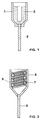
- FIG. 1 shows the structure of the electrode according to the invention in accordance with exemplary embodiments 1 to 4.
- These electrodes are a cup electrode for a T2 fluorescent lamp.
- These electrodes have a cup-like vessel 1 made of niobium, in the bottom of which a power supply 2 is attached.
- the cup-like vessel 1 is formed from a sheet which is squeezed over the power supply 2.
- the outer diameter of the cup-like vessel 1 is approximately 2 mm, its height is approximately 3.5 mm and its wall thickness is approximately 0.3 mm.
- the electron emitter 3 is arranged on the inner wall of the cup-like vessel 1.
- the electron emitter 3 consists of 40 mole percent barium zirconate BaZrO 3 , which is mixed with 30 mole percent zirconium Zr, 25 mole percent zirconium dioxide ZrO 2 and 5 mole percent calcium oxide CaO.
- the electron emitter 3 consists of 40 mol percent barium zirconate BaZrO 3 , that with 20 mol percent calcium zirconate CaZrO 3 , 20 mole percent zirconium Zr and 20 mole percent zirconium dioxide ZrO 2 is mixed.
- the electrode according to the third exemplary embodiment has an electron emitter with 50 mol percent barium zirconate BaZrO 3 , to which 30 mol percent iron Fe and 20 mol percent niobium Nb are mixed.
- the electron emitter of the electrode according to the invention consists of 90 mol percent barium zirconate BaZrO 3 , which is mixed with 10 mol percent hafnium Hf.
- the electrode of the fifth exemplary embodiment consists of 48 mol percent barium zirconate BaZrO 3 , to which 17 mol percent strontium zirconate SrZrO 3 and 35 mol percent titanium Ti are added.
- the experimentally determined electron work functions for the emitter compositions according to the exemplary embodiments 1 to 5 are listed for different temperature types.
- the table also contains corresponding comparison values for the standard emitter cited as prior art.
- FIG. 2 shows the structure of the electrodes in accordance with exemplary embodiments 6 to 10.
- These electrodes are also cold startable cup electrodes for a T2 fluorescent lamp.
- These electrodes have a cup-like vessel 4 made of niobium, in the bottom of which a power supply 5 is fastened.
- the cup-like vessel 4 is formed from an approximately 0.3 mm thick sheet which is squeezed over the power supply 5.
- the outer diameter of the cup-like vessel 4 is approximately 2 mm and its height is approximately 3.5 mm.
- a double helix 6 made of tantalum is arranged in the cup-like vessel 4. The winding axis this helix 6 runs coaxially to the cup axis.
- the windings of the helix 6 are in an inhibitory manner on the inner wall of the cup-like vessel 4.
- the electron emitter 7 is arranged on the filament 6 and fills the spaces between the windings of the filament 6 and the spaces between the filament 6 and the inner wall of the cup-like vessel 4.
- the emitter compositions of the exemplary embodiments 6 to 10 correspond to the emitter compositions of the exemplary embodiments 1 to 5 match.
- the electrodes of the exemplary embodiments 1 and 6 and 2 and 7 etc. therefore differ only in their structure, but not in the electron emitter.
- barium zirconate BaZrO 3 with a grain size of approximately 1.2 ⁇ m was used for the electron emitter.
- the metallic and oxidic additives were ground to a grain size of approx. 5 ⁇ m.
- the electrodes according to the invention were annealed before use in lamps under an inert gas atmosphere.
- the cup-like vessel 1, 4 can also consist of molybdenum, tantalum, nickel or iron and the coil 6 can consist of molybdenum, tungsten or niobium.
- the coil 6 can consist of molybdenum, tungsten or niobium.
- zirconium, hafnium, niobium and iron, nickel, tantalum, chromium, molybdenum, tungsten and vanadium are also suitable as metallic additives to the electron emitter.
- barium compounds Bariumhafnat (BaHfO 3), barium titanate (BaTiO 3) can be and barium cerate (BaCeO 3) was used instead of barium zirconate (BaZrO 3).
Landscapes
- Discharge Lamp (AREA)
- Luminescent Compositions (AREA)
Abstract
Description
Die Erfindung betrifft eine Elektrode für Entladungslampen gemäß dem Oberbegriff des Patentanspruchs 1.The invention relates to an electrode for discharge lamps according to the preamble of
Eine derartige, in Niederdruckentladungslampen verwendete Elektrode ist beispielsweise auf den Seiten 137 bis 139 des Buches ![]()
![]()
Die schweizer Patentschrift CH 449 117 offenbart eine gesinterte Elektrode für Gasentladungslampen, deren Elektronenemitter aus einer Mischung von Metallpulver mit Oxiden oder Peroxiden der Erdalkalimetalle hergestellt wird. Diese Mischung enthält vorzugsweise zwei Teile Oxide oder Peroxide der Erdalkalimetalle und ein Teil Metallpulver. Sie wird unter hohem Druck, ca. 1000-2000 kg/cm2, in den Elektrodenkörper eingepreßt und anschließend gesintert. Als Oxid und/oder Peroxid wird in dieser Patentschrift explizit Bariumoxid genannt und als Metallpulver werden Zirkon, Tantal und Wolfram aufgeführt. Der Herstellungsprozeß dieser Elektrode ist vergleichsweise aufwendig und die Elektrode zeigt keine ausreichende Kaltstartfestigkeit.Swiss patent CH 449 117 discloses a sintered electrode for gas discharge lamps, the electron emitter of which is produced from a mixture of metal powder with oxides or peroxides of the alkaline earth metals. This mixture preferably contains two parts of oxides or peroxides of the alkaline earth metals and one part of metal powder. It is pressed into the electrode body under high pressure, approx. 1000-2000 kg / cm 2 , and then sintered. This patent explicitly mentions barium oxide as the oxide and / or peroxide, and zirconium, tantalum and tungsten are listed as the metal powder. The manufacturing process of this electrode is comparatively complex and the electrode does not show sufficient cold start strength.
Aus der europäischen Offenlegungsschrift EP 0 253 316 sind kaltstartfähige Elektroden für Niederdruckentladungslampen bekannt, die im wesentlichen aus einem halbleitenden Porzellan bestehen. Diese Elektroden enthalten als Hauptbestandteil ein oder mehrere Oxide der Elemente Titan, Barium, Strontium, Kalzium, Lanthan und Zinn. Außerdem weisen sie ein oder mehrere Zusätze aus der Gruppe Y, Dy, Hf, Ce, Pr, Nd, Sm, Gd, Ho, Er, Tb, Sb, Nb, W, Yb, Sc und Ta auf. Die Herstellung dieser Elektroden ist zu kostenaufwendig. Außerdem eignen sich diese Elektroden nur für Niederdruckentladungslampen mit vergleichsweise geringen Betriebsströmen von bis zu ca. 50 mA, aber nicht für Betriebsströme von mehr als 100 mA wie sie in konventionellen Leuchtstofflampen auftreten.European patent application EP 0 253 316 discloses cold-startable electrodes for low-pressure discharge lamps, which essentially consist of a semiconducting porcelain. The main component of these electrodes contains one or more oxides of the elements titanium, barium, strontium, calcium, lanthanum and tin. They also have one or more additives from the group Y, Dy, Hf, Ce, Pr, Nd, Sm, Gd, Ho, Er, Tb, Sb, Nb, W, Yb, Sc and Ta. The production of these electrodes is too expensive. In addition, these electrodes are only suitable for low-pressure discharge lamps with comparatively low operating currents of up to approx. 50 mA, but not for operating currents of more than 100 mA as they occur in conventional fluorescent lamps.
Es ist die Aufgabe der Erfindung, eine Elektrode für Entladungslampen bereitzustellen, die eine verbesserte Schaltfestigkeit und eine verbesserte Kaltstartfähigkeit besitzt.It is the object of the invention to provide an electrode for discharge lamps which has an improved switching stability and an improved cold start capability.
Diese Aufgabe wird erfindungsgemäß durch die kennzeichnenden Merkmale des Patentanspruchs 1 gelöst. Besonders vorteilhafte Ausführungen der Erfindung sind in den Unteransprüchen beschrieben.This object is achieved by the characterizing features of
Die erfindungsgemäße Elektrode ist mit einen Elektronenemitter versehen, der als Hauptbestandteil eine Bariumverbindung aus der Gruppe Bariumzirkonat, Bariumhafnat, Bariumtitanat und Bariumcerat enthält und außerdem metallische Zusätze, vorzugsweise aus der Gruppe Zirkon, Hafnium, Eisen, Nickel, Niob und Tantal aufweist. Diese Bariumverbindungen zeichnen sich durch ihre im Vergleich zu Bariumoxid hohe chemische Stabilität aus. Außerdem entsteht beim Aktivieren der erfindungsgemäßen Elektrode keine heftige Gasentwicklung wie bei den obengenannten Karbonatemitterpasten, da sich das Bariumzirkonat bzw. Bariumhafnat bzw. Bariumtitanat bzw. Bariumcerat während dieses Prozesses nicht zersetzt. Als besonders vorteilhaft hat sich Bariumzirkonat BaZrO3 erwiesen. Es besitzt einen hohen Schmelzpunkt (ca. 2700°C) und ist insbesondere an Luft chemisch stabil und nicht hygroskopisch. Die metallischen Zusätze im Emitter wirken als Reduktionsmittel. Sie erzeugen im Bariumzirkonat bzw. Bariumhafnat bzw. Bariumtitanat bzw. Bariumcerat überschüssiges freies metallisches Barium, das dem Emitter halbleitende Eigenschaften und eine niedrige Elektronen-Austrittsarbeit gibt. Im Bariumzirkonat läuft die Reaktion dabei gemäß des nachstehenden Schemas ab: ![]()
![]()
Die Abkürzung Me im obigen Reaktionsschema steht für Zirkon oder Hafnium. Für die ebenfalls als Reduktionsmittel tauglichen Metalle Eisen, Nickel, Tantal und Niob und für die anderen Bariumverbindungen des erfindungsgemäßen Emitters lassen sich analoge Reaktionsgleichungen aufstellen.The abbreviation Me in the above reaction scheme stands for zircon or hafnium. For the metals iron, nickel, tantalum and niobium, which are also suitable as reducing agents, and for the other barium compounds of the invention Emitters can be used to set up analogous reaction equations.
Durch das überschüssige metallische Barium wird die Elektronen-Austrittsarbeit des Emitters von ca. 3 eV ― dem Wert für Bariumzirkonat entsprechend ― auf einen Wert von ca. 2 eV gesenkt. Der Anteil des Bariumzirkonates im Emitter beträgt dabei vorteilhafterweise 10 Molprozent bis 99 Molprozent während der Anteil der metallischen Zusätze zwischen 1 Molprozent und 90 Molprozent liegt. Besonders gut haben sich Bariumzirkonatanteile zwischen 40 Molprozent und 90 Molprozent sowie Anteile der metallischen Bestandteile in Höhe von 20 Molprozent bis 50 Molprozent bewährt. Bei diesen Zusammensetzungen des Emitters ist gewährleistet, daß die obengenannte Reaktion langsam genug abläuft, um ein vorzeitiges Erschöpfen des überschüssigen Bariums durch Abdampfen von der Elektrode zu verhindern. Die Reaktionsgeschwindigkeit der im obengenannten Reaktionsschema ablaufenden Reduktion läßt sich auch durch die Zugabe von Oxiden zum Emitter positiv beeinflussen. Bei einigen bevorzugten Ausführungsbeispielen der erfindungsgemäßen Elektrode werden dem Emitter zur Verringerung der Reaktionsgeschwindigkeit vorteilhafterweise Zirkondioxid und/oder Kalziumoxid zugesetzt. Der Anteil dieser Oxide am Elektronenemitter kann dabei vorteilhafterweise bis zu 50 Molprozent betragen. Bei einem bevorzugten Ausführungsbeispiel wurde dem Emitter zur weiteren Senkung der Elektronen-Austrittsarbeit vorteilhafterweise Kalziumzirkonat beigemischt.The excess metallic barium reduces the electron work function of the emitter from approx. 3 eV - corresponding to the value for barium zirconate - to a value of approx. 2 eV. The proportion of barium zirconate in the emitter is advantageously 10 mol percent to 99 mol percent while the proportion of metallic additives is between 1 mol percent and 90 mol percent. Barium zirconate fractions between 40 mole percent and 90 mole percent as well as fractions of the metallic components in the amount of 20 mole percent to 50 mole percent have proven particularly good. These compositions of the emitter ensure that the above reaction proceeds slowly enough to prevent the excess barium from being prematurely exhausted by evaporation from the electrode. The reaction rate of the reduction taking place in the above-mentioned reaction scheme can also be positively influenced by adding oxides to the emitter. In some preferred embodiments of the electrode according to the invention, zirconium dioxide and / or calcium oxide are advantageously added to the emitter in order to reduce the reaction rate. The proportion of these oxides in the electron emitter can advantageously be up to 50 mole percent. In a preferred embodiment, calcium zirconate was advantageously added to the emitter to further reduce the electron work function.
Bei einem der Ausführungsbeispiele wurde das Bariumzirkonat teilweise durch Strontiumzirkonat ersetzt. In diesem Fall entsteht neben dem freien überschüssigen Barium durch die metallischen Reduktionsmittel auch freies überschüssiges metallisches Strontium, das nach einem analogen Reaktionsschema, ähnlich wie oben für Bariumzirkonat beschrieben, die Elektronen-Austrittsarbeit des Emitters senkt und dem Emitter halbleitende Eigenschaften verleiht. Die Korngröße der Emitterbestandteile hat ebenfalls Einfluß auf die im Emitter ablaufende oben erläuterte Reaktion, bei der das überschüssige metallische Barium gebildet wird. Sie liegt vorteilhafterweise zwischen 1 µm und 20 µm.In one of the exemplary embodiments, the barium zirconate was partially replaced by strontium zirconate. In this case, in addition to the free excess barium, the metallic reducing agents also give rise to free excess metallic strontium which, according to an analogous reaction scheme, similar to that described above for barium zirconate, produces the electron work function of the emitter lowers and gives the emitter semiconducting properties. The grain size of the emitter constituents also has an influence on the above-described reaction in which the excess metallic barium is formed. It is advantageously between 1 µm and 20 µm.
Die erfindungsgemäße Elektrode ist vorteilhafterweise als kaltstartfähige Becherelektrode, die ein becherartiges Gefaß mit einer daran befestigten Stromzuführung aufweist, ausgebildet. Dadurch kann die erfindungsgemäße Elektrode auch in T1- und T2-Leuchtstofflampen eingesetzt werden, deren rohrförmiges Entladungsgefäß nur einen Durchmesser von ca. 1/8 Zoll bzw. 2/8 Zoll, d. h., 3,2 mm bzw. 6,4 mm besitzt und daher keine Bestückung mit den üblicherweise verwendeten Stabwendeln erlaubt. Besonders gut eignet sich die erfindungsgemäße Elektrode auch zum Einsatz in kompakten Leuchtstofflampen, die mittlerweile als energiesparender Ersatz für die Allgebrauchsglühlampe im Handel erhältlich sind. Die erfindungsgemäßen Elektroden weisen eine hohe Schaltfestigkeit auf. Untersuchungen haben gezeigt, daß die erfindungsgemäßen Elektroden mehr als 300.000 Kaltstarts überstehen, bei denen die Lampe nach jeweils 30 Sekunden ein- und wieder ausgeschaltet wurde. Bei den erfindungsgemäßen Becherelektroden ist der Emitter auf der Innenwand des becherartigen Gefäßes angebracht oder füllt bei einem besonders bevorzugten Ausführungsbeispiel die Zwischenräume einer Wendel, die im Inneren des becherartigen Gefäßes angeordnet ist. Die Wickelachse dieser Wendel verläuft dabei vorteilhafterweise parallel zur Becherachse, so daß die Wicklungen der Wendel mit Klemmsitz an der Becherinnenwand anliegen. Dadurch wird eine mögliche Schwärzung des Lampenkolbens durch absputterndes und verdampfendes Emittermaterial minimiert. Das becherartige Gefäß der erfindungsgemäßen Elektrode besteht vorteilhafterweise aus einem hochschmelzenden Metall aus der Gruppe Niob, Tantal, Molybdän, Eisen und Nickel. Die im Becher angeordnete Elektrodenwendel wird vorteilhafterweise aus Tantal, Molybdän oder Niob gefertigt.The electrode according to the invention is advantageously designed as a cold-startable cup electrode, which has a cup-like vessel with a power supply attached to it. As a result, the electrode according to the invention can also be used in T1 and T2 fluorescent lamps whose tubular discharge vessel has a diameter of only about 1/8 inch or 2/8 inch, ie, 3.2 mm or 6.4 mm, and therefore no assembly with the rod coils normally used is permitted. The electrode according to the invention is particularly well suited for use in compact fluorescent lamps, which are now commercially available as an energy-saving replacement for the general-purpose incandescent lamp. The electrodes according to the invention have a high switching stability. Investigations have shown that the electrodes according to the invention survive more than 300,000 cold starts, in which the lamp was switched on and off again after every 30 seconds. In the case of the cup electrodes according to the invention, the emitter is attached to the inner wall of the cup-like vessel or, in a particularly preferred exemplary embodiment, fills the spaces between a helix which is arranged in the interior of the cup-like vessel. The winding axis of this coil advantageously runs parallel to the cup axis, so that the windings of the coil with a clamp fit against the inside wall of the cup. This minimizes possible blackening of the lamp bulb due to sputtering and evaporating emitter material. The cup-like vessel of the electrode according to the invention advantageously consists of a high-melting metal from the group of niobium, tantalum, molybdenum, iron and nickel. The electrode coil arranged in the cup is advantageously made from tantalum, molybdenum or niobium.
Nachstehend wird die Erfindung anhand mehrerer Ausführungsbeispiele näher erläutert. Es zeigen:
Figur 1- Die Gestalt der erfindungsgemäßen Elektrode gemäß der
Ausführungsbeispiele 1 bis 4 Figur 2- Die Gestalt der erfindungsgemäßen Elektrode gemäß der
Ausführungsbeispiele 5 bis 8
- Figure 1
- The shape of the electrode according to the invention according to working examples 1 to 4
- Figure 2
- The shape of the electrode according to the invention according to working examples 5 to 8
Figur 1 zeigt den Aufbau der erfindungsgemäßen Elektrode entsprechend den Ausführungsbeispielen 1 bis 4. Bei diesen Elektroden handelt es sich um eine Becherelektrode für eine T2-Leuchtstofflampe. Diese Elektroden besitzen ein becherartiges, aus Niob bestehendes Gefäß 1, in dessen Boden eine Stromzuführung 2 befestigt ist. Das becherartige Gefäß 1 wird aus einem Blech geformt, das über der Stromzuführung 2 zugequetscht wird. Der Außendurchmesser des becherartigen Gefäßes 1 beträgt ca. 2 mm, seine Höhe mißt ungefähr 3,5 mm und seine Wandstärke beträgt ca. 0,3 mm. Der Elektronenemitter 3 ist an der Innenwand des becherartigen Gefäßes 1 angeordnet.FIG. 1 shows the structure of the electrode according to the invention in accordance with
Beim ersten Ausführungsbeispiel besteht der Elektronenemitter 3 aus 40 Molprozent Bariumzirkonat BaZrO3, das mit 30 Molprozent Zirkon Zr, 25 Molprozent Zirkondioxid ZrO2 und 5 Molprozent Kalziumoxid CaO vermischt ist.
Gemäß des zweiten Ausführungsbeispiels besteht der Elektronenemitter 3 aus 40 Molprozent Bariumzirkonat BaZrO3, das mit 20 Molprozent Kalziumzirkonat CaZrO3, 20 Molprozent Zirkon Zr und 20 Molprozent Zirkondioxid ZrO2 vermischt ist.In the first embodiment, the
According to the second exemplary embodiment, the
Die Elektrode gemäß des dritten Ausführungsbeispiels besitzt einen Elektronenemitter mit 50 Molprozent Bariumzirkonat BaZrO3, dem 30 Molprozent Eisen Fe und 20 Molprozent Niob Nb beigemischt sind.The electrode according to the third exemplary embodiment has an electron emitter with 50 mol percent barium zirconate BaZrO 3 , to which 30 mol percent iron Fe and 20 mol percent niobium Nb are mixed.
Beim vierten Ausführungsbeispiel besteht der Elektronenemitter der erfindungsgemäßen Elektrode aus 90 Molprozent Bariumzirkonat BaZrO3, das mit 10 Molprozent Hafnium Hf vermengt ist.In the fourth exemplary embodiment, the electron emitter of the electrode according to the invention consists of 90 mol percent barium zirconate BaZrO 3 , which is mixed with 10 mol percent hafnium Hf.
Die Elektrode des fünften Ausführungsbeispiels besteht aus 48 Molprozent Bariumzirkonat BaZrO3, dem 17 Molprozent Strontiumzirkonat SrZrO3 und 35 Molprozent Titan Ti hinzugefügt sind.The electrode of the fifth exemplary embodiment consists of 48 mol percent barium zirconate BaZrO 3 , to which 17 mol percent strontium zirconate SrZrO 3 and 35 mol percent titanium Ti are added.
In der Tabelle sind die experimentell ermittelten Elektronen-Austrittsarbeiten für die Emitterkompositionen gemäß der Ausführungsbeispiele 1 bis 5 für verschiedene Tempearturen aufgelistet. Außerdem enthält die Tabelle entsprechende Vergleichswerte für den als Stand der Technik zitierten Standardemitter.In the table, the experimentally determined electron work functions for the emitter compositions according to the
In Figur 2 ist der Aufbau der Elektroden gemäß der Ausführungsbeispiele 6 bis 10 dargestellt. Bei diesen Elektroden handelt es sich ebenfalls um kaltstartfähige Becherelektroden für eine T2-Leuchtstofflampe. Diese Elektroden weisen ein becherartiges, aus Niob bestehendes Gefäß 4 auf, in dessen Boden eine Stromzuführung 5 befestigt ist. Das becherartige Gefäß 4 ist aus einem ca. 0,3 mm dicken Blech geformt, das über der Stromzuführung 5 zugequetscht ist. Der Außendurchmesser des becherartigen Gefäßes 4 beträgt ca. 2 mm und seine Höhe mißt ungefähr 3,5 mm. Im becherartigen Gefäß 4 ist eine zweifach gewendelte Wendel 6 aus Tantal angeordnet. Die Wickelachse dieser Wendel 6 verläuft koaxial zur Becherachse. Außerdem liegen die Wicklungen der Wendel 6 Hemmend an der Innenwand des becherartigen Gefäßes 4 an. Der Elektronenemitter 7 ist auf der Wendel 6 angeordnet und füllt die Zwischenräume zwischen den Wicklungen der Wendel 6 sowie die Zwischenräume zwischen der Wendel 6 und der Innenwand des becherartigen Gefäßes 4. Die Emitterzusammensetzungen der Ausführungsbeispiele 6 bis 10 stimmen mit den Emitterzusammensetzungen der Ausführungsbeispiele 1 bis 5 überein. Die Elektroden der Ausführungsbeispiele 1 und 6 sowie 2 und 7 usw. unterscheiden sich also nur im Aufbau, nicht aber im Elektronenemitter.FIG. 2 shows the structure of the electrodes in accordance with
Bei allen Ausführungsbeispielen wurde für den Elektronenemitter Bariumzirkonat BaZrO3 mit einer Korngröße von ca. 1,2 µm verwendet. Die metallischen und oxidischen Zusätze wurden auf eine Korngröße von ca. 5 µm gemahlen. Zur Aktivierung des Emitters wurden die erfindungsgemäßen Elektroden vor dem Einsatz in Lampen unter Inertgasatmosphäre geglüht.In all of the exemplary embodiments, barium zirconate BaZrO 3 with a grain size of approximately 1.2 μm was used for the electron emitter. The metallic and oxidic additives were ground to a grain size of approx. 5 µm. To activate the emitter, the electrodes according to the invention were annealed before use in lamps under an inert gas atmosphere.
Die Erfindung beschrankt sich nicht auf die oben näher erläuterten Ausführungsbeispiele. Beispielsweise können bei den oben erläuterten Ausführungsbeispielen das becherartige Gefäß 1, 4 auch aus Molybdän, Tantal, Nickel oder Eisen und die Wendel 6 aus Molybdän, Wolfram oder Niob bestehen. Als metallische Zusätze zum Elektronenemitter eignen sich neben Zirkon, Hafnium, Niob und Eisen auch Nickel, Tantal, Chrom, Molybdän, Wolfram und Vanadium. Ferner können anstelle von Bariumzirkonat (BaZrO3) auch die Bariumverbindungen Bariumhafnat (BaHfO3), Bariumtitanat (BaTiO3) und Bariumcerat (BaCeO3) verwendet werden.
Claims (18)
Applications Claiming Priority (2)
| Application Number | Priority Date | Filing Date | Title |
|---|---|---|---|
| DE19616408 | 1996-04-24 | ||
| DE19616408A DE19616408A1 (en) | 1996-04-24 | 1996-04-24 | Electrode for discharge lamps |
Publications (2)
| Publication Number | Publication Date |
|---|---|
| EP0803898A2 true EP0803898A2 (en) | 1997-10-29 |
| EP0803898A3 EP0803898A3 (en) | 1997-12-29 |
Family
ID=7792333
Family Applications (1)
| Application Number | Title | Priority Date | Filing Date |
|---|---|---|---|
| EP97106015A Withdrawn EP0803898A3 (en) | 1996-04-24 | 1997-04-11 | Discharge lamp electrode |
Country Status (9)
| Country | Link |
|---|---|
| US (1) | US5880558A (en) |
| EP (1) | EP0803898A3 (en) |
| JP (1) | JPH1050252A (en) |
| KR (1) | KR970071987A (en) |
| CN (1) | CN1170954A (en) |
| CA (1) | CA2203330A1 (en) |
| DE (1) | DE19616408A1 (en) |
| HU (1) | HU218818B (en) |
| TW (1) | TW320733B (en) |
Families Citing this family (11)
| Publication number | Priority date | Publication date | Assignee | Title |
|---|---|---|---|---|
| EP1037244A3 (en) * | 1999-03-12 | 2003-01-08 | TDK Corporation | Electron-emitting material and preparing process |
| EP1285458A1 (en) | 2000-05-12 | 2003-02-26 | Koninklijke Philips Electronics N.V. | High-pressure electric discharge lamp |
| JP2002289139A (en) * | 2001-03-28 | 2002-10-04 | Matsushita Electric Ind Co Ltd | Cold cathode discharge lamp |
| DE10122392A1 (en) * | 2001-05-09 | 2002-11-14 | Philips Corp Intellectual Pty | Gas discharge lamp |
| US6603249B2 (en) * | 2001-09-24 | 2003-08-05 | Osram Sylvania Inc. | Fluorescent lamp with reduced sputtering |
| DE10242241A1 (en) * | 2002-09-12 | 2004-03-25 | Philips Intellectual Property & Standards Gmbh | Low pressure discharge lamp comprises a gas discharge vessel containing a noble gas filling, electrodes and devices for producing and maintaining a low pressure gas discharge, and an electron emitter substance |
| CN1306554C (en) * | 2004-04-20 | 2007-03-21 | 陈宗烈 | Hot-cathode fluorescent lamp without filament |
| US7633226B2 (en) * | 2005-11-30 | 2009-12-15 | General Electric Company | Electrode materials for electric lamps and methods of manufacture thereof |
| US8253331B2 (en) * | 2010-04-28 | 2012-08-28 | General Electric Company | Mercury dosing method for fluorescent lamps |
| CN104091740A (en) * | 2014-01-24 | 2014-10-08 | 朱惠冲 | High-strength rare earth molybdenum tube cold cathode and manufacturing process thereof |
| CN109686515B (en) * | 2018-12-30 | 2021-02-12 | 苏州团芯终端有限公司 | High-reliability PTC thermistor |
Citations (8)
| Publication number | Priority date | Publication date | Assignee | Title |
|---|---|---|---|---|
| US2687489A (en) * | 1952-06-26 | 1954-08-24 | Hanovia Chemical & Mfg Co | Electrode |
| CH449117A (en) * | 1964-07-08 | 1967-12-31 | Elin Union Ag | Process for the manufacture of sintered electrodes |
| US3558964A (en) * | 1968-10-21 | 1971-01-26 | Gen Electric | High current thermionic hollow cathode lamp |
| US4081713A (en) * | 1976-01-28 | 1978-03-28 | Hitachi, Ltd. | Directly heated oxide cathode |
| US4210840A (en) * | 1978-12-12 | 1980-07-01 | Westinghouse Electric Corp. | HID Lamp emission material |
| US5278474A (en) * | 1989-01-12 | 1994-01-11 | Tokyo Densoku Kabushiki Kaisha | Discharge tube |
| US5304893A (en) * | 1990-07-19 | 1994-04-19 | Tokyo Densoku Kabushiki Kaisha | Discharge tube having cup shape glow discharge electrode |
| EP0738423B1 (en) * | 1994-11-08 | 1999-01-13 | Koninklijke Philips Electronics N.V. | Low-pressure discharge lamp |
Family Cites Families (10)
| Publication number | Priority date | Publication date | Assignee | Title |
|---|---|---|---|---|
| US4105908A (en) * | 1976-04-30 | 1978-08-08 | General Electric Company | Metal halide lamp having open tungsten coil electrodes |
| KR900008794B1 (en) * | 1986-06-11 | 1990-11-29 | 티 디 케이 가부시끼가이샤 | Discharge lamp unit |
| KR920001844B1 (en) * | 1986-07-15 | 1992-03-05 | 티디 케이 가부시기가이샤 | Cold Cathode Discharge Light Device |
| JP2628314B2 (en) * | 1987-09-18 | 1997-07-09 | ティーディーケイ株式会社 | Cold cathode discharge lamp device |
| JP2881479B2 (en) * | 1990-06-08 | 1999-04-12 | ティーディーケイ株式会社 | Discharge electrode |
| JPH04272109A (en) * | 1991-02-27 | 1992-09-28 | Toshiba Corp | Electrode material for cold cathode fluorescent lamp and electrode constituted of the above |
| JPH0684579A (en) * | 1991-12-26 | 1994-03-25 | American Teleph & Telegr Co <Att> | Protective device of gas tube |
| FR2701597B1 (en) * | 1993-02-16 | 1995-05-19 | Jacques Villain | Cold cathode for gas discharge tube with a layer of alkaline earth compound on a metal support. |
| JPH07142027A (en) * | 1993-11-17 | 1995-06-02 | Noritake Co Ltd | Discharge tube |
| US5627430A (en) * | 1994-06-29 | 1997-05-06 | Ushiodenki Kabushiki Kaisha | Discharge lamp having a cathode with a sintered tip insert |
-
1996
- 1996-04-24 DE DE19616408A patent/DE19616408A1/en not_active Withdrawn
-
1997
- 1997-03-12 KR KR1019970008180A patent/KR970071987A/en not_active Withdrawn
- 1997-04-11 EP EP97106015A patent/EP0803898A3/en not_active Withdrawn
- 1997-04-16 TW TW086104916A patent/TW320733B/zh active
- 1997-04-21 JP JP9117555A patent/JPH1050252A/en active Pending
- 1997-04-22 CA CA002203330A patent/CA2203330A1/en not_active Abandoned
- 1997-04-23 US US08/847,547 patent/US5880558A/en not_active Expired - Lifetime
- 1997-04-23 HU HU9700799A patent/HU218818B/en not_active IP Right Cessation
- 1997-04-24 CN CN97110597A patent/CN1170954A/en active Pending
Patent Citations (8)
| Publication number | Priority date | Publication date | Assignee | Title |
|---|---|---|---|---|
| US2687489A (en) * | 1952-06-26 | 1954-08-24 | Hanovia Chemical & Mfg Co | Electrode |
| CH449117A (en) * | 1964-07-08 | 1967-12-31 | Elin Union Ag | Process for the manufacture of sintered electrodes |
| US3558964A (en) * | 1968-10-21 | 1971-01-26 | Gen Electric | High current thermionic hollow cathode lamp |
| US4081713A (en) * | 1976-01-28 | 1978-03-28 | Hitachi, Ltd. | Directly heated oxide cathode |
| US4210840A (en) * | 1978-12-12 | 1980-07-01 | Westinghouse Electric Corp. | HID Lamp emission material |
| US5278474A (en) * | 1989-01-12 | 1994-01-11 | Tokyo Densoku Kabushiki Kaisha | Discharge tube |
| US5304893A (en) * | 1990-07-19 | 1994-04-19 | Tokyo Densoku Kabushiki Kaisha | Discharge tube having cup shape glow discharge electrode |
| EP0738423B1 (en) * | 1994-11-08 | 1999-01-13 | Koninklijke Philips Electronics N.V. | Low-pressure discharge lamp |
Also Published As
| Publication number | Publication date |
|---|---|
| EP0803898A3 (en) | 1997-12-29 |
| HUP9700799A3 (en) | 1999-10-28 |
| HU9700799D0 (en) | 1997-06-30 |
| US5880558A (en) | 1999-03-09 |
| KR970071987A (en) | 1997-11-07 |
| TW320733B (en) | 1997-11-21 |
| DE19616408A1 (en) | 1997-10-30 |
| JPH1050252A (en) | 1998-02-20 |
| HU218818B (en) | 2000-12-28 |
| HUP9700799A2 (en) | 1998-04-28 |
| CA2203330A1 (en) | 1997-10-24 |
| CN1170954A (en) | 1998-01-21 |
Similar Documents
| Publication | Publication Date | Title |
|---|---|---|
| EP0652586B1 (en) | Metal-halide discharge lamp with a ceramic discharge tube and method of making the same | |
| DE10291427B4 (en) | Metal halide lamp for a motor vehicle headlight | |
| DE2753039C2 (en) | Electrode for a discharge lamp | |
| DE2626700A1 (en) | HIGH PRESSURE GAS DISCHARGE LAMP AND METHOD OF MANUFACTURING IT | |
| DE2161173B2 (en) | Oxide electrode for high-power electric gas discharge lamps | |
| DE69731374T2 (en) | LOW PRESSURE DISCHARGE LAMP | |
| EP0803898A2 (en) | Discharge lamp electrode | |
| DE69700155T2 (en) | Translucent polycrystalline alumina and manufacturing process | |
| DE1911985C3 (en) | High pressure arc discharge lamp | |
| DE2951741A1 (en) | ELECTRODE FOR A DISCHARGE LAMP | |
| DE3050460C2 (en) | Electric flash lamp | |
| DE69921901T2 (en) | Cermet and ceramic discharge lamp | |
| EP1032022B1 (en) | Metal halide lamp with ceramic discharge vessel | |
| DE19913867A1 (en) | Pulse generating capacitor used as a starter for a high pressure vapor discharge lamp | |
| EP1104933A2 (en) | Gas discharge lamp with an oxide emitter electrode | |
| DE69915966T2 (en) | Low-pressure mercury vapor discharge lamp | |
| DE944621C (en) | Activation material for electrodes of electrical discharge vessels | |
| DE2845283C2 (en) | ||
| DE2849606C3 (en) | Base metal plate material for directly heated oxide cathodes | |
| DE2714539A1 (en) | ELECTRODES OF A HIGH PRESSURE MERCURY VAPOR DISCHARGE LAMP | |
| EP0592915B1 (en) | Low-pressure discharge lamp and process for producing a low-pressure discharge lamp | |
| DE10044451C1 (en) | Electrode and capacitor with the electrode | |
| EP0759633B1 (en) | High pressure discharge lamp | |
| DE69911538T2 (en) | LOW PRESSURE MERCURY VAPOR DISCHARGE LAMP | |
| DE2935447C2 (en) | Directly heated sintered electrode |
Legal Events
| Date | Code | Title | Description |
|---|---|---|---|
| PUAI | Public reference made under article 153(3) epc to a published international application that has entered the european phase |
Free format text: ORIGINAL CODE: 0009012 |
|
| AK | Designated contracting states |
Kind code of ref document: A2 Designated state(s): BE DE ES FR GB IT NL SE |
|
| PUAL | Search report despatched |
Free format text: ORIGINAL CODE: 0009013 |
|
| AK | Designated contracting states |
Kind code of ref document: A3 Designated state(s): BE DE ES FR GB IT NL SE |
|
| 17P | Request for examination filed |
Effective date: 19980121 |
|
| 17Q | First examination report despatched |
Effective date: 19990909 |
|
| STAA | Information on the status of an ep patent application or granted ep patent |
Free format text: STATUS: THE APPLICATION IS DEEMED TO BE WITHDRAWN |
|
| 18D | Application deemed to be withdrawn |
Effective date: 20010620 |