EP0803884B1 - Capacitor and its manufacturing method - Google Patents
Capacitor and its manufacturing method Download PDFInfo
- Publication number
- EP0803884B1 EP0803884B1 EP96306619A EP96306619A EP0803884B1 EP 0803884 B1 EP0803884 B1 EP 0803884B1 EP 96306619 A EP96306619 A EP 96306619A EP 96306619 A EP96306619 A EP 96306619A EP 0803884 B1 EP0803884 B1 EP 0803884B1
- Authority
- EP
- European Patent Office
- Prior art keywords
- sheet
- foil sheet
- rolling
- sheets
- positive
- Prior art date
- Legal status (The legal status is an assumption and is not a legal conclusion. Google has not performed a legal analysis and makes no representation as to the accuracy of the status listed.)
- Expired - Lifetime
Links
- 238000004519 manufacturing process Methods 0.000 title claims description 6
- 239000003990 capacitor Substances 0.000 title description 2
- 239000011888 foil Substances 0.000 claims description 123
- 238000005096 rolling process Methods 0.000 claims description 81
- 238000000034 method Methods 0.000 claims description 12
- 230000001105 regulatory effect Effects 0.000 claims description 9
- 238000003825 pressing Methods 0.000 claims description 4
- 230000005540 biological transmission Effects 0.000 description 7
- XAGFODPZIPBFFR-UHFFFAOYSA-N aluminium Chemical compound [Al] XAGFODPZIPBFFR-UHFFFAOYSA-N 0.000 description 5
- 229910052782 aluminium Inorganic materials 0.000 description 5
- 238000003860 storage Methods 0.000 description 4
- 238000007789 sealing Methods 0.000 description 3
- 230000007547 defect Effects 0.000 description 2
- 229920003002 synthetic resin Polymers 0.000 description 2
- 239000000057 synthetic resin Substances 0.000 description 2
- 238000004873 anchoring Methods 0.000 description 1
- 239000002131 composite material Substances 0.000 description 1
- 238000007796 conventional method Methods 0.000 description 1
- 239000012530 fluid Substances 0.000 description 1
Images


Classifications
-
- H—ELECTRICITY
- H01—ELECTRIC ELEMENTS
- H01G—CAPACITORS; CAPACITORS, RECTIFIERS, DETECTORS, SWITCHING DEVICES, LIGHT-SENSITIVE OR TEMPERATURE-SENSITIVE DEVICES OF THE ELECTROLYTIC TYPE
- H01G4/00—Fixed capacitors; Processes of their manufacture
- H01G4/32—Wound capacitors
-
- H—ELECTRICITY
- H01—ELECTRIC ELEMENTS
- H01G—CAPACITORS; CAPACITORS, RECTIFIERS, DETECTORS, SWITCHING DEVICES, LIGHT-SENSITIVE OR TEMPERATURE-SENSITIVE DEVICES OF THE ELECTROLYTIC TYPE
- H01G11/00—Hybrid capacitors, i.e. capacitors having different positive and negative electrodes; Electric double-layer [EDL] capacitors; Processes for the manufacture thereof or of parts thereof
- H01G11/22—Electrodes
- H01G11/26—Electrodes characterised by their structure, e.g. multi-layered, porosity or surface features
-
- H—ELECTRICITY
- H01—ELECTRIC ELEMENTS
- H01G—CAPACITORS; CAPACITORS, RECTIFIERS, DETECTORS, SWITCHING DEVICES, LIGHT-SENSITIVE OR TEMPERATURE-SENSITIVE DEVICES OF THE ELECTROLYTIC TYPE
- H01G11/00—Hybrid capacitors, i.e. capacitors having different positive and negative electrodes; Electric double-layer [EDL] capacitors; Processes for the manufacture thereof or of parts thereof
- H01G11/78—Cases; Housings; Encapsulations; Mountings
- H01G11/82—Fixing or assembling a capacitive element in a housing, e.g. mounting electrodes, current collectors or terminals in containers or encapsulations
-
- H—ELECTRICITY
- H01—ELECTRIC ELEMENTS
- H01G—CAPACITORS; CAPACITORS, RECTIFIERS, DETECTORS, SWITCHING DEVICES, LIGHT-SENSITIVE OR TEMPERATURE-SENSITIVE DEVICES OF THE ELECTROLYTIC TYPE
- H01G13/00—Apparatus specially adapted for manufacturing capacitors; Processes specially adapted for manufacturing capacitors not provided for in groups H01G4/00 - H01G11/00
- H01G13/02—Machines for winding capacitors
-
- H—ELECTRICITY
- H01—ELECTRIC ELEMENTS
- H01G—CAPACITORS; CAPACITORS, RECTIFIERS, DETECTORS, SWITCHING DEVICES, LIGHT-SENSITIVE OR TEMPERATURE-SENSITIVE DEVICES OF THE ELECTROLYTIC TYPE
- H01G9/00—Electrolytic capacitors, rectifiers, detectors, switching devices, light-sensitive or temperature-sensitive devices; Processes of their manufacture
- H01G9/004—Details
- H01G9/04—Electrodes or formation of dielectric layers thereon
- H01G9/06—Mounting in containers
-
- H—ELECTRICITY
- H01—ELECTRIC ELEMENTS
- H01G—CAPACITORS; CAPACITORS, RECTIFIERS, DETECTORS, SWITCHING DEVICES, LIGHT-SENSITIVE OR TEMPERATURE-SENSITIVE DEVICES OF THE ELECTROLYTIC TYPE
- H01G9/00—Electrolytic capacitors, rectifiers, detectors, switching devices, light-sensitive or temperature-sensitive devices; Processes of their manufacture
- H01G9/15—Solid electrolytic capacitors
- H01G9/151—Solid electrolytic capacitors with wound foil electrodes
-
- H—ELECTRICITY
- H01—ELECTRIC ELEMENTS
- H01G—CAPACITORS; CAPACITORS, RECTIFIERS, DETECTORS, SWITCHING DEVICES, LIGHT-SENSITIVE OR TEMPERATURE-SENSITIVE DEVICES OF THE ELECTROLYTIC TYPE
- H01G9/00—Electrolytic capacitors, rectifiers, detectors, switching devices, light-sensitive or temperature-sensitive devices; Processes of their manufacture
- H01G9/004—Details
- H01G9/04—Electrodes or formation of dielectric layers thereon
- H01G9/048—Electrodes or formation of dielectric layers thereon characterised by their structure
- H01G9/055—Etched foil electrodes
-
- Y—GENERAL TAGGING OF NEW TECHNOLOGICAL DEVELOPMENTS; GENERAL TAGGING OF CROSS-SECTIONAL TECHNOLOGIES SPANNING OVER SEVERAL SECTIONS OF THE IPC; TECHNICAL SUBJECTS COVERED BY FORMER USPC CROSS-REFERENCE ART COLLECTIONS [XRACs] AND DIGESTS
- Y02—TECHNOLOGIES OR APPLICATIONS FOR MITIGATION OR ADAPTATION AGAINST CLIMATE CHANGE
- Y02E—REDUCTION OF GREENHOUSE GAS [GHG] EMISSIONS, RELATED TO ENERGY GENERATION, TRANSMISSION OR DISTRIBUTION
- Y02E60/00—Enabling technologies; Technologies with a potential or indirect contribution to GHG emissions mitigation
- Y02E60/13—Energy storage using capacitors
-
- Y—GENERAL TAGGING OF NEW TECHNOLOGICAL DEVELOPMENTS; GENERAL TAGGING OF CROSS-SECTIONAL TECHNOLOGIES SPANNING OVER SEVERAL SECTIONS OF THE IPC; TECHNICAL SUBJECTS COVERED BY FORMER USPC CROSS-REFERENCE ART COLLECTIONS [XRACs] AND DIGESTS
- Y02—TECHNOLOGIES OR APPLICATIONS FOR MITIGATION OR ADAPTATION AGAINST CLIMATE CHANGE
- Y02T—CLIMATE CHANGE MITIGATION TECHNOLOGIES RELATED TO TRANSPORTATION
- Y02T10/00—Road transport of goods or passengers
- Y02T10/60—Other road transportation technologies with climate change mitigation effect
- Y02T10/70—Energy storage systems for electromobility, e.g. batteries
-
- Y—GENERAL TAGGING OF NEW TECHNOLOGICAL DEVELOPMENTS; GENERAL TAGGING OF CROSS-SECTIONAL TECHNOLOGIES SPANNING OVER SEVERAL SECTIONS OF THE IPC; TECHNICAL SUBJECTS COVERED BY FORMER USPC CROSS-REFERENCE ART COLLECTIONS [XRACs] AND DIGESTS
- Y10—TECHNICAL SUBJECTS COVERED BY FORMER USPC
- Y10T—TECHNICAL SUBJECTS COVERED BY FORMER US CLASSIFICATION
- Y10T29/00—Metal working
- Y10T29/43—Electric condenser making
- Y10T29/435—Solid dielectric type
Definitions
- the present invention relates to method and device for producing a condenser, according, respectively, to claims 1 and 2, and more particularly relates to rolling up into a roll a positive foil sheet, a negative foil sheet and an isolating sheet which are placed one on another in combination with a plurality of lead terminals and another plurality of lead terminals attached to the positive foil sheet and the negative foil sheet respectively with a predetermined space provided therebetween while a rotational drive roller is pressed against the circumferentially outer surface of the roll to eliminate the tensions which may be applied to the combined sheets as the sheets are rolled up thereby to arrange the each plurality of lead terminals in alignment in respective radial directions of the roll.
- the present invention will enable condensers of extremely large capacity to be produced at a reduced cost as a secondary battery which may be employed, for example, for electric vehicles.
- the above-mentioned isolating sheets are such that they are placed between the positive foil sheet and the negative foil sheet to isolate the one from the other, and may be paper, a synthetic resin film, etc., in case of a film condenser, and an electrolytic paper in the case of an electrolytic condenser.
- film condensers and electrolytic condensers have been produced by rolling up into a condenser element a positive foil sheet, a negative foil sheet and an isolating sheet which are placed one on another in combination while a lead terminal is attached to the positive foil sheet and the negative foil sheet respectively.
- the condenser element is inserted into an aluminum housing having a bottom.
- the condenser produced in this manner may have an electric capacity between the positive foil sheet and the negative foil sheet. With the two lead terminals protruding out of the aluminum housing, the condenser is connected to an electric circuit.
- a condenser 1 of a large capacity is often produced with a plurality of negative lead terminals 2 and another plurality of positive lead elements 3 attached to the negative foil sheet 5 and the positive foil sheet 4 respectively so as to reduce the surge impedance and increase the property of the condenser.
- the conventional method for producing the condenser is to anchor to a sheet rolling up shaft (not shown) one end of the positive foil sheet 4, the negative foil sheet 5 and the isolating sheet 6 which are placed one on another in combination, and to rotate the sheet rolling up shaft to roll up the combined sheets as supplied from a sheet supplying source (not shown).
- the sheet rolling up method the combined sheets are subjected to the fluctuating tensions caused from the sheet rolling up movement. Especially the precededly rolled up sheets are more intensely tightened as the sheets are incrementally rolled up. Actually it has been difficult to roll up the combined sheets with an even degree of tension all through the radial direction of the roll.
- the condenser rolled up with uneven degrees of tension will come to have the negative lead terminals 2 and the positive lead terminals 3 circumferentially shifted from each other respectively. Such circumferentially shifted lead terminals have caused inconvenience when the condenser is connected to an electric circuit.
- DE 1 298 186 discloses a method for producing a condenser by rolling un electrode foil sheets and an isolating sheet there between, each of the electrode foil sheets having a lead terminal attached thereto said method comprising the steps of: a) rolling up electrode foil sheets and said isolating foil sheet by rotating a sheet rolling shaft; b) and rotating a drive roller and pressing said roller against the outer surface of the roll of combined said electrode and isolating sheets carried by said sheet rolling up shaft and said drive roller takes part in rolling up said sheets in cooperation with said sheet rolling up shaft.
- GB 853 846 refers the attachment of a plurality of terminals in a roll capacitor element further disclosing that during the rolling process, the lead terminals to one electrode are aligned along one radial direction of said roll.
- a method for producing a condenser according to claim 1 by rolling up a positive foil sheet, a negative foil sheet and an isolating sheet which are placed one on another in combination, each of the positive foil sheet and the negative foil sheet having a lead terminal attached thereto, said method comprising the steps of:
- a device for producing a condenser according to claim 2 by rolling up a positive foil sheet, a negative foil sheet and an isolating sheet which are placed one on another in combination, each of the positive foil sheet and the negative foil sheet having a plurality of lead terminals attached thereto said device comprising:
- a condenser producing device 20 is provided with a lead terminal attaching section (though it is not shown), a sheet rolling up section 21 and an auxiliary rolling up section 22.
- a condenser 10 produced by the condenser producing device 20 is substantially composed of a positive foil sheet 11, a negative foil sheet 12, an isolating sheet 13, positive lead terminals 14 and negative lead terminals 15 as shown in Figs.1 through 3.
- the condenser 10 is composed of a condenser element 16 made up of the positive foil sheet 11 having a plurality of positive lead terminals 14 fixedly attached thereto, the negative foil sheet 12 having a plurality of negative lead terminals 15 fixedly attached thereto and the isolating sheet 13 placed between the positive foil sheet 11 and the negative foil sheet 12, the sheets 11, 12, 13 being integrally rolled up while the plurality of positive lead elements 14 are positioned at circumferentially the same phase and arranged in alignment in one radial direction of the condenser and the plurality of negative lead elements 15 are placed at circumferencially the same phase in alignment in another radial direction of the condenser.
- the isolating sheet 13 is placed between the positive and negative foil sheets 11 and 12 to isolate the one from the other.
- the isolating sheet 13 may be paper, a synthetic resin film, etc. in the case of a film condenser and may be electrolytic paper in the case of an electrolytic condenser.
- the plurality of positive and negative lead terminals 14,15 are bent at the bases thereof to be brought into contact with each other in each group.
- the condenser element 16 is subsequently inserted into an aluminum housing 19 having a bottom and is covered with a sealing member 18 which is inserted into the open end of the housing 19 while the contacted positive and negative lead terminals 14,15 extend out of the aluminum housing 19 through holes 18a of the sealing member 18 respectively.
- the housing 19 is then processed to have the open end constricted into a neck 19a.
- the aluminum housing 19 is sealed with the sealing member 18.
- the lead terminal attaching section (though this is not shown) is provided to fixedly attach the positive and negative lead terminals 14,15 to the respective positive and negative foil sheets 11,12 with a predetermined space provided therebetween.
- This section is composed of a subsection for automatically supplying the positive and negative lead terminals 14,15 and another subsection for automatically fixing the supplied positive and negative lead terminals 14,15 to the respective positive and negative foil sheets 11,12.
- This section is so structured as to process the positive and negative lead terminals 14,15 to make spot facings thereon respectively and fixedly attach the lead terminals 14,15 to the positive and negative foil sheets 11,12 respectively with a predetermined space provided therebetween as the sheets 11,12 come to the section guided by guide rollers 23 respectively from the rolled sheet supplies.
- the sheet rolling up section 21 is provided to integrally roll up the positive foil sheet 11, the negative foil sheet 12 and the isolating sheet 13, and includes a rolling up shaft 25 which is rotatable and axially movable on a swingable arm (not shown) which is mounted on a base frame 24.
- the rolling up shaft 25 has a groove 25a axially formed thereon for anchoring thereto the positive and negative foil sheets 11,12 and the isolating sheet 13 which are placed one on another in combination.
- the rolling up shaft 25 is rotated by an electric motor 28 having a rotational shaft 29 and mounted on the base frame 24 and the rotation transmission means including a pulley 30 secured to the rotational shaft 29, another pulley 26 secured to the rolling up shaft 25 and an endless transmission belt 31 extended around the two pulleys 26,30.
- the electric motor 28 is a servomotor driven at a rotation speed and with its number of rotations regulated by a control section (not shown).
- the electric motor 28 is set to rotate at a rotation speed to be reduced as the diameter of the rolled condenser element 16 becomes larger so that the positive and negative foil sheets 11,12 and the isolating sheet 13 are rolled up at a constant speed. Further the electric motor 28 is set to rotate until the motor comes to a predetermined total number of rotations.
- the auxiliary rolling up section 22 is so structured as to give a rotational pressure to the circumferentially outer surface of the positive and negative foil sheets 11,12 and the isolating sheet 13 which are placed one on another so as to roll up these sheets in cooperation with the sheet rolling up shaft 25.
- the auxiliary rolling up section 22 includes a movable base 34 having a dovetail groove 33 secured thereto which is in slidable engagement with a guide member 32 fixedly mounted on the base frame 24, so that the movable base 34 may be vertically slidable.
- the movable base 34 has a rubber roller 36 rotationally driven at the lower end thereof on a shaft 35.
- the rubber roller 36 is rotated by an electric motor 39 having a rotational shaft 40 and arranged on the base frame 24 and transmission means including a pulley 38 secured to the shaft 35, another pulley 41 secured to the rotational shaft 40 and an endless transmission belt 42 extended around the pulleys 38,41.
- the electric motor 39 is a servomotor, which is so called a torque motor, driven with a constant rotation torque regulated by a control section (not shown).
- the electric motor 39 is employed to roll up with a constant torque the positive and negative foil sheets 11,12 and the isolating sheet 13 while these sheets 11,12,13 are transported at a constant speed with the rubber drive roller 36 being pressed against the circumferentially outer surface 17 of the sheets.
- the movable base 34 is fixedly connected to a piston rod 44 of a pneumatic cylinder which is mounted on the base frame 24.
- the pneumatic cylinder 43 is driven by a compressed air supplied to fluid pressure supply openings 43a,43b thereof, thereby to axially move the movable base 34 together with the rubber drive roller 36 in the direction where the rubber drive roller 36 will be pressed against the circumferentially outer surface 17 of the sheets 11,12,13 and in the opposite direction where the rubber drive roller 36 is away therefrom.
- a tension roller 45 is provided to pressingly contact the endless transmission belt 42 so as to give a tension thereto.
- the tension may be adjusted with positional adjustment of a holder 48 holding the tension roller 45 by manipulating fixing screws 46.
- the condenser production method includes the steps of placing a positive foil sheet 11, a negative foil sheet 12 and an isolating sheet 13 one on another in combination, the positive foil sheet 11 having positive lead terminals attached thereto and the negative foil sheet 12 having negative lead terminals attached thereto, and rolling up the positive and negative foil sheets 11,12 and the isolating sheet 13.
- the method includes: (I) fixedly attaching a plurality of positive lead terminals 14 to the positive foil sheet 11 with a predetermined space provided therebetween and a plurality of negative lead terminals 15 to the negative foil sheet 15 with a predetermined space provided therebetween; (II) rotating the sheet rolling up shaft 25 to roll up the so combined positive and negative foil sheets 11,12 and isolating sheet 13 while one end of the sheets 11, 12, 13 is anchored to the sheet rolling up shaft 25, and (III) in the meantime,pressing a drive roller 36 as it is rotated against the circumferentially outer surface 17 of the positive and negative foil sheets 11,12,13 while these sheets are rolled up, so that the roller 36 will cooperate with the sheet rolling up shaft 25 to prevent the rolled sheets from being unevenly tightened and to position the plurality of positive lead terminals 14 in one group at circumferentially the same phase and arranging the same in alignment in one radial direction of the roll, and to position the plurality of negative lead terminals 15 in the other group at circumferentially the same phase and
- the roller 36 may be pressed against the circumferentially outer surface of the rolled sheets 11,12,13 after the first positive and negative lead terminals 14,15 in the respective groups have been rolled up.
- the embodiment of the invention is structured as mentioned above, and the operation is as follows: with reference to Fig. 11 showing a section 49, for convenience sake, for supplying only the positive foil sheet 11, the rolled positive foil sheet 11 is set onto a roll shaft 50 of the sheet supplying section 49 and is unrolled to the sheet rolling up shaft 25 while the positive foil sheet 11 is guided by the plurality of guide rollers 23,and the end of the sheet 11 is anchored to the groove 25a of the sheet rolling up shaft 25 of the sheet rolling up section 21, so that the anchored sheet may be rolled up as the sheet rolling up shaft 25 is rotated.
- the negative foil sheet 12 and the isolating sheet 13 are separately set to the respective sheet supplying sections 49 and unrolled to the sheet rolling up shaft 25 of the sheet rolling up section 21.
- a first isolating sheet 13 is located at the uppermost position. Below the isolating sheet 13, the positive foil sheet 11 is located. Below the positive foil sheet 11, a second isolating sheet 13 is located. Below the second isolating sheet 13, the negative foil sheet 12 is located. Below the negative foil sheet 12, a third isolating sheet 13 is located.
- the servomotor 28 is driven at a regulated rotation speed in the direction as indicated by the arrow A.
- the rotation is transmitted to the sheet rolling up shaft 25 through the pulley 30, the endless transmission belt 31 and the pulley 26.
- the sheet rolling up shaft 25 is rotated at a regulated constant speed in the direction as indicated by the arrow B, and integrally rolls up the positive foil sheet 11, the negative foil sheet 12 and the isolating sheets 13 which are anchored to the rolling up shaft 25.
- the lead terminal attaching section (not shown) is operated to process a first positive lead terminal 14 to make a spot facing thereon and fixedly attach the terminal 14 to the positive foil sheet 11 and then similarly process a first negative lead terminal 15 to make a spot facing thereon and fixedly attach the terminal 15 to the negative foil sheet 12.
- the electric motor 28 is driven in the direction as indicated by the arrow A thereby to rotate the rolling up shaft 25 in the direction as indicated by the arrow B.
- the rolling up shaft 25 is rotated at a constant speed and rolls up the positive and negative foil sheets 11,12 and the isolating sheets 13 as these sheets are supplied from the sheet supplying section 49.
- compressed air is supplied to the pneumatic cylinder 43.
- the pneumatic cylinder 43 is then operated to extend the piston rod 44 thereby to move down the movable base 34 in the direction as indicated by the arrow F until the drive roller 36 is pressed against the circumferentially outer surface 17 of the sheets 11,12,13 as these sheets are rolled up.
- the drive motor (torque motor) 39 is regulated to rotate with a constant torque and at a constant speed in the direction as indicated by the arrow D.
- the rotation is transmitted to the drive motor 36 through the pulley 41, the endless transmission belt 42, the pulley 38 and the shaft 35, and the drive motor 36 is rotated in the direction as indicated by the arrow E at a constant speed and with a constant torque while the circumferential surface thereof is pressed against the condenser element 16.
- the drive roller 36 pressed against the circumferential surface 17 of the condenser element 16 will cooperate with the sheet rolling up shaft 25 to roll up the positive and negative foil sheets 11,12 and the isolating sheets 13 around the sheet rolling up shaft 25 in the direction as indicated by the arrow B.
- the lead attaching section is operated to process the next positive lead terminal 14 to make a spot facing thereon and fixedly attach the processed lead terminal 14 to the positive foil sheet 11, and then the lead attaching section is operated to process the next negative lead terminal 15 to make a spot facing thereon and fixedly attach the processed lead 15 to the negative foil sheet 12.
- the positive and negative foil sheets 11,12 and the isolating sheets 13 supplied from the sheet supplying section 49 are subjected to fluctuating tensions caused by the periodical operation movements of a sheet supplying arm 51.
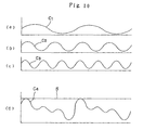
- the periodical tension indicated by the curve C1 as shown in Fig.10(a) is applied to the positive foil sheet 11.
- the periodical tension indicated by the curve C2 as shown in Fig.10(b) is applied to the positive foil sheet 12.
- the periodical tension indicated by the curve C3 as shown in Fig.10(c) is applied to the isolating sheets 13.
- the rolling up shaft 25 is subjected to the periodical tension indicated by the complicated curve C4 which is composed of the aforementioned three curves C1,C2,C3 as shown in Fig.10 (d). Therefore if the rolling up shaft 25 is simply rotated to roll up the positive and negative foil sheets 11,12 and the isolating sheets 13, the mentioned composite tension is applied to the sheets 11,12,13 while these sheets are rolled up and tightens the roll. Further as the roll is variably tightened in accordance with the fluctuation of the tension as indicated by the curve C4, the positive and negative foil sheets 11,12 and the isolating sheets 13 will not be rolled up with an even degree of tension all through the rolling up process. As a result, the positive lead terminals 14 and the negative lead terminals 15 are circumferentially shifted from the respectively predetermined circumferential phases as the sheets are rolled up.
- the positive and negative foil sheets 11,12 and the isolating sheets 13 are rolled up by cooperation of the rolling up shaft 25 and the drive roller 36 which is rotated with the rolling up shaft 25 with a constant torque and at a constant rotation speed. Therefore the tension, which may otherwise be applied to the precededly rolled sheets 11,12,13, is eliminated at the sheet rolling up place, and the sheets 11,12,13 are continued to be rolled up with a constant tension S as shown in Fig.10(d). The sheets 11,12,13 are therefore free of the tension which may cause the roll to be unevenly tightened,and may be rolled up with an even and constant tension.
- the three positive lead terminals 14 and the three negative lead terminals 15 maybe positioned at circumferentially the same phases respectively of the roll.
- a condenser of extremely large capacity and of light weight may be easily made up.
- a condenser of a diameter more than 50mm ⁇ and of a length more than 150mm and a bigger condenser may be easily made up.
- a condenser of very light weight and of large capacity may be obtained as a secondary battery,for example, for an electric motor vehicle.
- the auxiliary rolling up section 22 is arranged above the sheet rolling up shaft 25.
- the auxiliary rolling up section 22 may be arranged below the rolling up shaft 25 and simultaneously the drive roller 36 may be arranged below the condenser element 16 so that the drive motor may be pressed against the condenser element 16 from below or obliquely from below.
- rolling up shaft 25 and the drive roller 36 are driven by way of the endless belts respectively in this embodiment. But these may be directly connected to respective electric motors.
Landscapes
- Engineering & Computer Science (AREA)
- Power Engineering (AREA)
- Microelectronics & Electronic Packaging (AREA)
- Manufacturing & Machinery (AREA)
- Fixed Capacitors And Capacitor Manufacturing Machines (AREA)
Description
- The present invention relates to method and device for producing a condenser, according, respectively, to claims 1 and 2, and more particularly relates to rolling up into a roll a positive foil sheet, a negative foil sheet and an isolating sheet which are placed one on another in combination with a plurality of lead terminals and another plurality of lead terminals attached to the positive foil sheet and the negative foil sheet respectively with a predetermined space provided therebetween while a rotational drive roller is pressed against the circumferentially outer surface of the roll to eliminate the tensions which may be applied to the combined sheets as the sheets are rolled up thereby to arrange the each plurality of lead terminals in alignment in respective radial directions of the roll. Thus the present invention will enable condensers of extremely large capacity to be produced at a reduced cost as a secondary battery which may be employed, for example, for electric vehicles. The above-mentioned isolating sheets are such that they are placed between the positive foil sheet and the negative foil sheet to isolate the one from the other, and may be paper, a synthetic resin film, etc., in case of a film condenser, and an electrolytic paper in the case of an electrolytic condenser.
- So far, film condensers and electrolytic condensers have been produced by rolling up into a condenser element a positive foil sheet, a negative foil sheet and an isolating sheet which are placed one on another in combination while a lead terminal is attached to the positive foil sheet and the negative foil sheet respectively. The condenser element is inserted into an aluminum housing having a bottom. The condenser produced in this manner may have an electric capacity between the positive foil sheet and the negative foil sheet. With the two lead terminals protruding out of the aluminum housing, the condenser is connected to an electric circuit.
- In FIG.12, a
condenser 1 of a large capacity is often produced with a plurality of negative lead terminals 2 and another plurality ofpositive lead elements 3 attached to thenegative foil sheet 5 and thepositive foil sheet 4 respectively so as to reduce the surge impedance and increase the property of the condenser. The conventional method for producing the condenser is to anchor to a sheet rolling up shaft (not shown) one end of thepositive foil sheet 4, thenegative foil sheet 5 and theisolating sheet 6 which are placed one on another in combination, and to rotate the sheet rolling up shaft to roll up the combined sheets as supplied from a sheet supplying source (not shown). However according to the sheet rolling up method, the combined sheets are subjected to the fluctuating tensions caused from the sheet rolling up movement. Especially the precededly rolled up sheets are more intensely tightened as the sheets are incrementally rolled up. Actually it has been difficult to roll up the combined sheets with an even degree of tension all through the radial direction of the roll. - The condenser rolled up with uneven degrees of tension will come to have the negative lead terminals 2 and the
positive lead terminals 3 circumferentially shifted from each other respectively. Such circumferentially shifted lead terminals have caused inconvenience when the condenser is connected to an electric circuit. - On the other hand, in place of vehicles driven by gasoline engines and/or diesel engines which are now at issue over pollution due to car exhausts, electric motor vehicles have come to be developed. However, defects of an electric motor vehicle are as follows: (I) the storage battery is very heavy, (II) the running distance is short per charging, (III) charging requires a long time, (IV) the cost is expensive, and so on. In order to eliminate such defects, various storage batteries have been proposed and have contributed, although slightly, to the practical use of electric motor vehicles. Under the present circumstances a wide use of electric vehicles is a far way to realization, and the future perspective remains obscure. This is because a storage battery has not been developed, which is of light weight and may be repeatedly charged and discharged, and furthermore is of a large capacity but can be charged in a short time and produced at a reduced cost.
DE 1 298 186 discloses a method for producing a condenser by rolling un electrode foil sheets and an isolating sheet there between, each of the electrode foil sheets having a lead terminal attached thereto said method comprising the steps of: a) rolling up electrode foil sheets and said isolating foil sheet by rotating a sheet rolling shaft; b) and rotating a drive roller and pressing said roller against the outer surface of the roll of combined said electrode and isolating sheets carried by said sheet rolling up shaft and said drive roller takes part in rolling up said sheets in cooperation with said sheet rolling up shaft. GB 853 846 refers the attachment of a plurality of terminals in a roll capacitor element further disclosing that during the rolling process, the lead terminals to one electrode are aligned along one radial direction of said roll. - According to the present invention, there is provided a method for producing a condenser according to
claim 1 by rolling up a positive foil sheet, a negative foil sheet and an isolating sheet which are placed one on another in combination, each of the positive foil sheet and the negative foil sheet having a lead terminal attached thereto, said method comprising the steps of: - a) attaching a plurality of lead terminals to said positive foil sheet and said negative foil sheet respectively with a predetermined space provided therebetween;
- b) rotating a sheet rolling up shaft at a regulated constant speed to roll up said positive foil sheet; said negative foil sheet and said isolating sheet therearound;
- c) rotating a drive roller at a predetermined constant rotation torque and pressing said drive roller against the circumferentially outer surface of the roll of said sheets carried by said sheet rolling up shaft so that said drive roller takes part in rolling up said sheets in cooperation with said sheet rolling up shaft, wherein said positive foil sheet, said negative foil sheet and said isolating sheets are prevented from being unevenly tightened as these sheets are rolled up, and wherein said plurality of lead terminals of said positive foil sheet are positioned at circumferentially the same phase of said roll and are arranged in alignment with each other in one radial direction of said roll and said plurality of lead terminals of said negative foil sheet are positioned at circumferentially the same phase of said roll and are arranged in alignment with each other in another radial direction of said roll.
-
- According to the present invention, there is further provided a device for producing a condenser according to claim 2 by rolling up a positive foil sheet, a negative foil sheet and an isolating sheet which are placed one on another in combination, each of the positive foil sheet and the negative foil sheet having a plurality of lead terminals attached thereto said device comprising:
- a) attaching means operable to attach said lead terminals to said positive foil sheet and said negative foil sheet respectively with a predetermined space therebetween;
- b) sheet rolling up means including a sheet rolling up shaftrotated in use at a regulated constant speed to roll up said positive foil sheet, said negative foil sheet, and said isolating sheet therearound; and
- c) auxiliary rolling up means including a drive roller rotated in use at a predetermined rotating torque and pressed against the circumferentially outer surface of the roll of said sheets carried by said sheet rolling up shaft so that said drive roller takes part in rolling up said sheets in cooperation with said sheet rolling up shaft, wherein said positive foil sheet, said negative foil sheet and said isolating sheet are prevented from being unevenly tightened as these sheets are rolled up and wherein said plurality of lead terminals of said positive foil sheet are positioned at circumferentially the same phase of said roll and are arranged in alignment with each other in one radial direction of said roll and said plurality of lead terminals of said negative foil sheet are positioned at circumferentially the same phase of said roll and are arranged in alignment with each other in another radial direction of said roll.
-
- The present invention will now be described, by way of example, with reference to the accompanying drawings, in which:-
- Fig. 1 is a perspective view of a condenser shown partly in section;
- Fig. 2 is a vertical sectional view of the condenser;
- Fig. 3 is a perspective view of part of the condenser;
- Fig. 4 is a perspective view of essential parts of a condenser producing device;
- Fig. 5 is a front elevational view of the essential parts of the condenser producing device;
- Fig. 6 is a side elevational view of the essential parts of the condenser producing device;
- Fig. 7 is a front elevational view of the essential parts of the condenser producing device showing the beginning of rolling up the condenser sheets;
- Fig. 8 is a front elevational view of the parts showing a drive roller just starting to be driven;
- Fig. 9 is front elevational view of the drive roller and a sheet rolling up shaft rolling up the condenser sheets in cooperation;
- Fig.10 is a graphical representation of fluctuating tensions applied to a positive foil sheet, a negative foil sheet and an isolating sheet which form the condenser;
- Fig.11 is a front elevational view of the parts for eliminating the tensions to be applied to the precededly rolled up positive foil sheet, negative foil sheet and isolating sheet; and
- Fig.12 is a perspective view of the conventional condenser element.
-
- The present invention will now be described with reference to the embodiment as shown in the accompanying drawings. In Figs. 4 through 6, a
condenser producing device 20 is provided with a lead terminal attaching section (though it is not shown), a sheet rolling upsection 21 and an auxiliary rolling upsection 22. Acondenser 10 produced by thecondenser producing device 20 is substantially composed of apositive foil sheet 11, anegative foil sheet 12, anisolating sheet 13,positive lead terminals 14 andnegative lead terminals 15 as shown in Figs.1 through 3. - Particularly with reference to Fig.3, the
condenser 10 is composed of acondenser element 16 made up of thepositive foil sheet 11 having a plurality ofpositive lead terminals 14 fixedly attached thereto, thenegative foil sheet 12 having a plurality ofnegative lead terminals 15 fixedly attached thereto and theisolating sheet 13 placed between thepositive foil sheet 11 and thenegative foil sheet 12, thesheets positive lead elements 14 are positioned at circumferentially the same phase and arranged in alignment in one radial direction of the condenser and the plurality ofnegative lead elements 15 are placed at circumferencially the same phase in alignment in another radial direction of the condenser. Theisolating sheet 13 is placed between the positive andnegative foil sheets isolating sheet 13 may be paper, a synthetic resin film, etc. in the case of a film condenser and may be electrolytic paper in the case of an electrolytic condenser. - With reference to Figs.1 and 2, the plurality of positive and
negative lead terminals condenser element 16 is subsequently inserted into analuminum housing 19 having a bottom and is covered with a sealingmember 18 which is inserted into the open end of thehousing 19 while the contacted positive andnegative lead terminals aluminum housing 19 throughholes 18a of the sealingmember 18 respectively. Thehousing 19 is then processed to have the open end constricted into a neck 19a. Thus thealuminum housing 19 is sealed with the sealingmember 18. - Now with reference to Figs. 4 through 6 showing the
condenser producing device 20, the lead terminal attaching section (though this is not shown) is provided to fixedly attach the positive andnegative lead terminals negative foil sheets negative lead terminals negative lead terminals negative foil sheets negative lead terminals lead terminals negative foil sheets sheets guide rollers 23 respectively from the rolled sheet supplies. - The sheet rolling up
section 21 is provided to integrally roll up thepositive foil sheet 11, thenegative foil sheet 12 and theisolating sheet 13, and includes a rolling upshaft 25 which is rotatable and axially movable on a swingable arm (not shown) which is mounted on abase frame 24. The rolling upshaft 25 has agroove 25a axially formed thereon for anchoring thereto the positive andnegative foil sheets isolating sheet 13 which are placed one on another in combination. - The rolling up
shaft 25 is rotated by anelectric motor 28 having arotational shaft 29 and mounted on thebase frame 24 and the rotation transmission means including apulley 30 secured to therotational shaft 29, anotherpulley 26 secured to the rolling upshaft 25 and anendless transmission belt 31 extended around the twopulleys - The
electric motor 28 is a servomotor driven at a rotation speed and with its number of rotations regulated by a control section (not shown). Theelectric motor 28 is set to rotate at a rotation speed to be reduced as the diameter of the rolledcondenser element 16 becomes larger so that the positive andnegative foil sheets isolating sheet 13 are rolled up at a constant speed. Further theelectric motor 28 is set to rotate until the motor comes to a predetermined total number of rotations. - The auxiliary rolling up
section 22 is so structured as to give a rotational pressure to the circumferentially outer surface of the positive andnegative foil sheets isolating sheet 13 which are placed one on another so as to roll up these sheets in cooperation with the sheet rolling upshaft 25. The auxiliary rolling upsection 22 includes amovable base 34 having adovetail groove 33 secured thereto which is in slidable engagement with aguide member 32 fixedly mounted on thebase frame 24, so that themovable base 34 may be vertically slidable. - The
movable base 34 has arubber roller 36 rotationally driven at the lower end thereof on ashaft 35. Therubber roller 36 is rotated by anelectric motor 39 having arotational shaft 40 and arranged on thebase frame 24 and transmission means including apulley 38 secured to theshaft 35, anotherpulley 41 secured to therotational shaft 40 and anendless transmission belt 42 extended around thepulleys - The
electric motor 39 is a servomotor, which is so called a torque motor, driven with a constant rotation torque regulated by a control section (not shown). Theelectric motor 39 is employed to roll up with a constant torque the positive andnegative foil sheets sheet 13 while thesesheets rubber drive roller 36 being pressed against the circumferentiallyouter surface 17 of the sheets. - The
movable base 34 is fixedly connected to apiston rod 44 of a pneumatic cylinder which is mounted on thebase frame 24. Thepneumatic cylinder 43 is driven by a compressed air supplied to fluidpressure supply openings movable base 34 together with therubber drive roller 36 in the direction where therubber drive roller 36 will be pressed against the circumferentiallyouter surface 17 of thesheets rubber drive roller 36 is away therefrom. - A
tension roller 45 is provided to pressingly contact theendless transmission belt 42 so as to give a tension thereto. The tension may be adjusted with positional adjustment of aholder 48 holding thetension roller 45 by manipulating fixing screws 46. - The condenser production method according to the present invention includes the steps of placing a
positive foil sheet 11, anegative foil sheet 12 and an isolatingsheet 13 one on another in combination, thepositive foil sheet 11 having positive lead terminals attached thereto and thenegative foil sheet 12 having negative lead terminals attached thereto, and rolling up the positive andnegative foil sheets sheet 13. More particularly, the method includes: (I) fixedly attaching a plurality ofpositive lead terminals 14 to thepositive foil sheet 11 with a predetermined space provided therebetween and a plurality ofnegative lead terminals 15 to thenegative foil sheet 15 with a predetermined space provided therebetween; (II) rotating the sheet rolling upshaft 25 to roll up the so combined positive andnegative foil sheets sheet 13 while one end of thesheets shaft 25, and (III) in the meantime,pressing adrive roller 36 as it is rotated against the circumferentiallyouter surface 17 of the positive andnegative foil sheets roller 36 will cooperate with the sheet rolling upshaft 25 to prevent the rolled sheets from being unevenly tightened and to position the plurality ofpositive lead terminals 14 in one group at circumferentially the same phase and arranging the same in alignment in one radial direction of the roll, and to position the plurality ofnegative lead terminals 15 in the other group at circumferentially the same phase and arranging the same in alignment in another radial direction of the roll. - In the above mentioned condenser production method, the
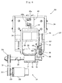
roller 36 may be pressed against the circumferentially outer surface of the rolledsheets negative lead terminals - The embodiment of the invention is structured as mentioned above, and the operation is as follows: with reference to Fig. 11 showing a
section 49, for convenience sake, for supplying only thepositive foil sheet 11, the rolledpositive foil sheet 11 is set onto aroll shaft 50 of thesheet supplying section 49 and is unrolled to the sheet rolling upshaft 25 while thepositive foil sheet 11 is guided by the plurality ofguide rollers 23,and the end of thesheet 11 is anchored to thegroove 25a of the sheet rolling upshaft 25 of the sheet rolling upsection 21, so that the anchored sheet may be rolled up as the sheet rolling upshaft 25 is rotated. - In the same manner, the
negative foil sheet 12 and the isolatingsheet 13 are separately set to the respectivesheet supplying sections 49 and unrolled to the sheet rolling upshaft 25 of the sheet rolling upsection 21. In Fig.11, a first isolatingsheet 13 is located at the uppermost position. Below the isolatingsheet 13, thepositive foil sheet 11 is located. Below thepositive foil sheet 11, a second isolatingsheet 13 is located. Below the second isolatingsheet 13, thenegative foil sheet 12 is located. Below thenegative foil sheet 12, a third isolatingsheet 13 is located. - With reference to Fig.7, with the aforementioned swingable arm (not shown) being turned to about 15° in the clockwise direction, the
servomotor 28 is driven at a regulated rotation speed in the direction as indicated by the arrow A. The rotation is transmitted to the sheet rolling upshaft 25 through thepulley 30, theendless transmission belt 31 and thepulley 26. Thus the sheet rolling upshaft 25 is rotated at a regulated constant speed in the direction as indicated by the arrow B, and integrally rolls up thepositive foil sheet 11, thenegative foil sheet 12 and the isolatingsheets 13 which are anchored to the rolling upshaft 25. - When a predetermined amount of the positive and
negative foil sheets sheets 13 is rolled up, the lead terminal attaching section (not shown) is operated to process a firstpositive lead terminal 14 to make a spot facing thereon and fixedly attach the terminal 14 to thepositive foil sheet 11 and then similarly process a firstnegative lead terminal 15 to make a spot facing thereon and fixedly attach the terminal 15 to thenegative foil sheet 12. - When the first
positive lead terminal 14 and thefirst lead terminal 15 have been rolled up as thesheets shaft 25, the swingable arm is turned in the direction as indicated by the arrow C to move the rolling upshaft 25 to a position vertically opposite to therubber drive roller 36. - Subsequently in Fig. 8, the
electric motor 28 is driven in the direction as indicated by the arrow A thereby to rotate the rolling upshaft 25 in the direction as indicated by the arrow B. The rolling upshaft 25 is rotated at a constant speed and rolls up the positive andnegative foil sheets sheets 13 as these sheets are supplied from thesheet supplying section 49. When a predetermined amount of thesheets pneumatic cylinder 43. Thepneumatic cylinder 43 is then operated to extend thepiston rod 44 thereby to move down themovable base 34 in the direction as indicated by the arrow F until thedrive roller 36 is pressed against the circumferentiallyouter surface 17 of thesheets - The drive motor (torque motor) 39 is regulated to rotate with a constant torque and at a constant speed in the direction as indicated by the arrow D. The rotation is transmitted to the
drive motor 36 through thepulley 41, theendless transmission belt 42, thepulley 38 and theshaft 35, and thedrive motor 36 is rotated in the direction as indicated by the arrow E at a constant speed and with a constant torque while the circumferential surface thereof is pressed against thecondenser element 16. - The
drive roller 36 pressed against thecircumferential surface 17 of thecondenser element 16 will cooperate with the sheet rolling upshaft 25 to roll up the positive andnegative foil sheets sheets 13 around the sheet rolling upshaft 25 in the direction as indicated by the arrow B. When a predetermined amount of thesheets lead terminal 14 to thepositive foil sheet 11, and then the lead attaching section is operated to process the nextnegative lead terminal 15 to make a spot facing thereon and fixedly attach the processedlead 15 to thenegative foil sheet 12. - The same operation is repeated as the
sheets positive lead terminals 14 and threenegative lead terminals 15 are attached one after another to thepositive foil sheet 11 and thenegative foil sheet 12 respectively in this embodiment. Thus when a predetermined total amount of the positive andnegative foil sheets sheets 13 is rolled up, theelectric motor 28 and thedrive motor 39 are stopped, and the rolling upshaft 25 is axially moved out of the rolled upsheets condenser element 16 is made up. - With reference to Figs. 10 and 11, the positive and
negative foil sheets sheets 13 supplied from thesheet supplying section 49 are subjected to fluctuating tensions caused by the periodical operation movements of asheet supplying arm 51. For example, referring to Fig.10, the periodical tension indicated by the curve C1 as shown in Fig.10(a) is applied to thepositive foil sheet 11. The periodical tension indicated by the curve C2 as shown in Fig.10(b) is applied to thepositive foil sheet 12. The periodical tension indicated by the curve C3 as shown in Fig.10(c) is applied to the isolatingsheets 13. The rolling upshaft 25 is subjected to the periodical tension indicated by the complicated curve C4 which is composed of the aforementioned three curves C1,C2,C3 as shown in Fig.10 (d). Therefore if the rolling upshaft 25 is simply rotated to roll up the positive andnegative foil sheets sheets 13, the mentioned composite tension is applied to thesheets negative foil sheets sheets 13 will not be rolled up with an even degree of tension all through the rolling up process. As a result, thepositive lead terminals 14 and thenegative lead terminals 15 are circumferentially shifted from the respectively predetermined circumferential phases as the sheets are rolled up. - However according to the present invention, the positive and
negative foil sheets sheets 13 are rolled up by cooperation of the rolling upshaft 25 and thedrive roller 36 which is rotated with the rolling upshaft 25 with a constant torque and at a constant rotation speed. Therefore the tension, which may otherwise be applied to the precededly rolledsheets sheets sheets positive lead terminals 14 and the threenegative lead terminals 15 maybe positioned at circumferentially the same phases respectively of the roll. Thus by using the invention, a condenser of extremely large capacity and of light weight may be easily made up. For example, a condenser of a diameter more than 50mm and of a length more than 150mm and a bigger condenser may be easily made up. More particularly by using the invention, in place of a very heavy lead storage battery, a condenser of very light weight and of large capacity may be obtained as a secondary battery,for example, for an electric motor vehicle. - In this embodiment,the auxiliary rolling up
section 22 is arranged above the sheet rolling upshaft 25. However it is needless to say that the invention is only limited by the appended claims, hence is not limited to the embodiment. The auxiliary rolling upsection 22 may be arranged below the rolling upshaft 25 and simultaneously thedrive roller 36 may be arranged below thecondenser element 16 so that the drive motor may be pressed against thecondenser element 16 from below or obliquely from below. - Further the rolling up
shaft 25 and thedrive roller 36 are driven by way of the endless belts respectively in this embodiment. But these may be directly connected to respective electric motors.
Claims (2)
- A method for producing a condenser (10) by rolling up a positive foil sheet (11), a negative foil sheet (12) and an isolating sheet (13) which are placed one on another in combination, each of the positive foil sheet (11) and the negative foil sheet (12) having a lead terminal (14 or 15) attached thereto, said method comprising the steps ofa) attaching a plurality of lead terminals (14, 15) to said positive foil sheet (11) and said negative foil sheet (12) respectively with a predetermined space provided therebetween;b) rotating a sheet rolling up shaft (25) at a regulated constant speed to roll up said positive foil sheet (11), said negative foil sheet (12) and said isolating sheet (13) therearound;c) rotating a drive roller (36) at a predetermined constant rotation torque and pressing said drive roller (36) against the circumferentially outer surface (17) of the roll of said sheets (11,12,13) carried by said sheet rolling up shaft (25) so that said drive roller (36) takes part in rolling up said sheets (11,12,13) in cooperation with said sheet rolling up shaft (25), wherein said positive foil sheet (11), said negative foil sheet (12) and said isolating sheets (13) are prevented from being unevenly tightened as these sheets are rolled up, and wherein said plurality of lead terminals (14) of said positive foil sheet(11) are positioned at circumferentially the same phase of said roll and are arranged in alignment with each other in one radial direction of said roll and said plurality of lead terminals (15) of said negative foil sheet (12) are positioned at circumferentially the same phase of said roll and are arranged in alignment with each other in another radial direction of said roll.
- A device (20) for producing a condenser (10) by rolling up a positive foil sheet (11), a negative foil sheet (12) and an isolating sheet (13) which are placed one on another in combination, each of the positive foil sheet (11) and the negative foil sheet (12) having a plurality of lead terminals (14 or 15) attached thereto, said device comprising:a) attaching means operable to attach said lead terminals (14,15) to said positive foil sheet (11) and said negative foil sheet (12) respectively with a predetermined space therebetween;b) sheet rolling up means including a sheet rolling up shaft (25) rotated in use at a regulated constant speed to roll up said positive foil sheet (11), said negative foil sheet (12) and said isolating sheet (13) therearound; andc) auxiliary rolling up means including a drive roller (36) rotated in use at a predetermined rotating torque and pressed against the circumferentially outer surface (17) of the roll of said sheets (11,12,13) carried by said sheet rolling up shaft (25) so that said drive roller (36) takes part in rolling up said sheets in cooperation with said sheet rolling up shaft (25), wherein said positive foil sheet (11), said negative foil sheet (12) and said isolating sheet (13) are prevented from beingunevenly tightened as these sheets are rolled up and wherein said plurality of lead terminals (14) of said positive foil sheet (11) are positioned at circumferentially the same phase of said roll and are arranged in alignment with each other in one radial direction of said roll and said plurality of lead terminals (15) of said negative foil sheet (12) are positioned at circumferentially the same phase of said roll and are arranged in alignment with each other in another radial direction of said roll.
Applications Claiming Priority (3)
| Application Number | Priority Date | Filing Date | Title |
|---|---|---|---|
| JP12111896 | 1996-04-17 | ||
| JP121118/96 | 1996-04-17 | ||
| JP8121118A JPH09293628A (en) | 1996-04-17 | 1996-04-17 | Capacitor and manufacturing method thereof |
Publications (3)
| Publication Number | Publication Date |
|---|---|
| EP0803884A2 EP0803884A2 (en) | 1997-10-29 |
| EP0803884A3 EP0803884A3 (en) | 1999-12-08 |
| EP0803884B1 true EP0803884B1 (en) | 2005-11-23 |
Family
ID=14803338
Family Applications (1)
| Application Number | Title | Priority Date | Filing Date |
|---|---|---|---|
| EP96306619A Expired - Lifetime EP0803884B1 (en) | 1996-04-17 | 1996-09-12 | Capacitor and its manufacturing method |
Country Status (4)
| Country | Link |
|---|---|
| US (1) | US5850678A (en) |
| EP (1) | EP0803884B1 (en) |
| JP (1) | JPH09293628A (en) |
| DE (1) | DE69635476T2 (en) |
Families Citing this family (3)
| Publication number | Priority date | Publication date | Assignee | Title |
|---|---|---|---|---|
| CN1971785B (en) * | 2005-11-22 | 2014-09-17 | 三洋电机株式会社 | electrolytic capacitor |
| JP4587996B2 (en) * | 2005-11-22 | 2010-11-24 | 佐賀三洋工業株式会社 | Electrolytic capacitor |
| JP7041401B2 (en) * | 2019-06-27 | 2022-03-24 | 株式会社村田製作所 | Manufacturing method and pressing equipment for laminated ceramic electronic components |
Family Cites Families (11)
| Publication number | Priority date | Publication date | Assignee | Title |
|---|---|---|---|---|
| US2328520A (en) * | 1943-08-31 | Condenser winding machine | ||
| US1385379A (en) * | 1917-01-26 | 1921-07-26 | American Bosch Magneto Corp | Electrical condenser and method of making it |
| US1841628A (en) * | 1927-11-23 | 1932-01-19 | Gen Electric | Electrical condenser |
| US2248621A (en) * | 1938-12-13 | 1941-07-08 | Gen Electric | Method of fabricating welded assemblies |
| GB853846A (en) * | 1956-11-19 | 1960-11-09 | Freiberg Kondensatorenwerk | Improvements in or relating to wide-band interference-suppression-condensers |
| US3163374A (en) * | 1960-04-28 | 1964-12-29 | Varta Ag | Method of and apparatus for the manufacture of condensers and electrodes for cells in storage batteries and the like |
| DE1298186B (en) * | 1963-03-08 | 1969-06-26 | Elektromat Veb | Capacitor winding machine for automatic winding of capacitors of small dimensions |
| DE2159866A1 (en) * | 1971-12-02 | 1973-06-14 | Heinz Scheibe | METHOD FOR MANUFACTURING REELS FROM FILM TAPES, E.G. CAPACITOR WINDING |
| US4377891A (en) * | 1980-11-13 | 1983-03-29 | Cladan Incorporated | Method and apparatus for fabricating multilayer tubular electrical components |
| JP2770278B2 (en) * | 1987-01-14 | 1998-06-25 | 毅 池田 | Noise filter and method of manufacturing the same |
| JP2574694Y2 (en) * | 1991-12-10 | 1998-06-18 | 株式会社皆藤製作所 | Winding device for film capacitor element material |
-
1996
- 1996-04-17 JP JP8121118A patent/JPH09293628A/en active Pending
- 1996-09-12 EP EP96306619A patent/EP0803884B1/en not_active Expired - Lifetime
- 1996-09-12 DE DE69635476T patent/DE69635476T2/en not_active Expired - Fee Related
- 1996-09-20 US US08/717,326 patent/US5850678A/en not_active Expired - Fee Related
Also Published As
| Publication number | Publication date |
|---|---|
| US5850678A (en) | 1998-12-22 |
| DE69635476D1 (en) | 2005-12-29 |
| JPH09293628A (en) | 1997-11-11 |
| DE69635476T2 (en) | 2006-06-08 |
| EP0803884A2 (en) | 1997-10-29 |
| EP0803884A3 (en) | 1999-12-08 |
Similar Documents
| Publication | Publication Date | Title |
|---|---|---|
| CN111048844B (en) | High-speed lamination method for lithium battery | |
| US4137690A (en) | Apparatus for wrapping paper rolls | |
| US6692602B1 (en) | Machine for producing a corrugated cardboard sheet and process for calibrating the glue gap of such a machine | |
| US11196032B2 (en) | Electrode sheet rolling press having a short stress line and integrated apparatus for manufacturing lithium battery electrode sheet | |
| CN106825109A (en) | The processing unit (plant) of thin-wall barrel | |
| CN112193544A (en) | Coiled material packaging equipment | |
| EP0803884B1 (en) | Capacitor and its manufacturing method | |
| US5000364A (en) | Apparatus for obtaining differential tangential variable speeds at different points of a deformable film | |
| CN218756023U (en) | Roll-to-roll vacuum coating machine and compression roller device used by same | |
| CN221066181U (en) | Assembling platform for processing hybrid power assembly | |
| CN116689212B (en) | High-precision thickness-control uniform coating device for lithium battery pole piece | |
| CA1263856A (en) | Apparatus for winding film | |
| CN115611043B (en) | Battery recycling and winding device | |
| CN109338732B (en) | Preparation device and method of environment-friendly flame-retardant PVC artificial leather | |
| CN110386511B (en) | Material collecting and discharging structure of laminating machine | |
| CA1189433A (en) | Method and apparatus for covering flexible symmetrical angulate tubes with sheet material | |
| CN206703675U (en) | Plastic film compounding machine | |
| CN206663943U (en) | Plastic film compounding machine | |
| CN112027740A (en) | Roller prick leather replacing device and using method | |
| CN218491019U (en) | Packing belt winding mechanism | |
| CN219044726U (en) | Film pressing roll shaft device and low-tension coil separator | |
| CN223148857U (en) | Rotary picking and placing device | |
| CN222006793U (en) | Paper feeding mechanism of handkerchief paper folding machine | |
| KR0168586B1 (en) | Automatic Beading Device for Lithium Battery Can | |
| US5310106A (en) | Apparatus for obtaining differential tangential variable speeds at different points of a deformable film |
Legal Events
| Date | Code | Title | Description |
|---|---|---|---|
| PUAI | Public reference made under article 153(3) epc to a published international application that has entered the european phase |
Free format text: ORIGINAL CODE: 0009012 |
|
| AK | Designated contracting states |
Kind code of ref document: A2 Designated state(s): DE FR GB IT NL |
|
| PUAL | Search report despatched |
Free format text: ORIGINAL CODE: 0009013 |
|
| AK | Designated contracting states |
Kind code of ref document: A3 Designated state(s): DE FR GB IT NL |
|
| 17P | Request for examination filed |
Effective date: 20000530 |
|
| 17Q | First examination report despatched |
Effective date: 20030411 |
|
| GRAP | Despatch of communication of intention to grant a patent |
Free format text: ORIGINAL CODE: EPIDOSNIGR1 |
|
| GRAS | Grant fee paid |
Free format text: ORIGINAL CODE: EPIDOSNIGR3 |
|
| GRAA | (expected) grant |
Free format text: ORIGINAL CODE: 0009210 |
|
| AK | Designated contracting states |
Kind code of ref document: B1 Designated state(s): DE FR GB IT NL |
|
| REG | Reference to a national code |
Ref country code: GB Ref legal event code: FG4D |
|
| REF | Corresponds to: |
Ref document number: 69635476 Country of ref document: DE Date of ref document: 20051229 Kind code of ref document: P |
|
| ET | Fr: translation filed | ||
| PLBE | No opposition filed within time limit |
Free format text: ORIGINAL CODE: 0009261 |
|
| STAA | Information on the status of an ep patent application or granted ep patent |
Free format text: STATUS: NO OPPOSITION FILED WITHIN TIME LIMIT |
|
| 26N | No opposition filed |
Effective date: 20060824 |
|
| PGFP | Annual fee paid to national office [announced via postgrant information from national office to epo] |
Ref country code: DE Payment date: 20070901 Year of fee payment: 12 |
|
| PGFP | Annual fee paid to national office [announced via postgrant information from national office to epo] |
Ref country code: GB Payment date: 20070706 Year of fee payment: 12 |
|
| PGFP | Annual fee paid to national office [announced via postgrant information from national office to epo] |
Ref country code: NL Payment date: 20070930 Year of fee payment: 12 Ref country code: IT Payment date: 20070924 Year of fee payment: 12 |
|
| PGFP | Annual fee paid to national office [announced via postgrant information from national office to epo] |
Ref country code: FR Payment date: 20070918 Year of fee payment: 12 |
|
| GBPC | Gb: european patent ceased through non-payment of renewal fee |
Effective date: 20080912 |
|
| PG25 | Lapsed in a contracting state [announced via postgrant information from national office to epo] |
Ref country code: NL Free format text: LAPSE BECAUSE OF NON-PAYMENT OF DUE FEES Effective date: 20090401 |
|
| NLV4 | Nl: lapsed or anulled due to non-payment of the annual fee |
Effective date: 20090401 |
|
| REG | Reference to a national code |
Ref country code: FR Ref legal event code: ST Effective date: 20090529 |
|
| PG25 | Lapsed in a contracting state [announced via postgrant information from national office to epo] |
Ref country code: IT Free format text: LAPSE BECAUSE OF NON-PAYMENT OF DUE FEES Effective date: 20080912 Ref country code: DE Free format text: LAPSE BECAUSE OF NON-PAYMENT OF DUE FEES Effective date: 20090401 |
|
| PG25 | Lapsed in a contracting state [announced via postgrant information from national office to epo] |
Ref country code: FR Free format text: LAPSE BECAUSE OF NON-PAYMENT OF DUE FEES Effective date: 20080930 |
|
| PG25 | Lapsed in a contracting state [announced via postgrant information from national office to epo] |
Ref country code: GB Free format text: LAPSE BECAUSE OF NON-PAYMENT OF DUE FEES Effective date: 20080912 |