EP0803686A2 - Humidificateur d'air fonctionnant au gaz - Google Patents
Humidificateur d'air fonctionnant au gaz Download PDFInfo
- Publication number
- EP0803686A2 EP0803686A2 EP97302816A EP97302816A EP0803686A2 EP 0803686 A2 EP0803686 A2 EP 0803686A2 EP 97302816 A EP97302816 A EP 97302816A EP 97302816 A EP97302816 A EP 97302816A EP 0803686 A2 EP0803686 A2 EP 0803686A2
- Authority
- EP
- European Patent Office
- Prior art keywords
- humidifier
- water
- steam
- water tank
- combustion
- Prior art date
- Legal status (The legal status is an assumption and is not a legal conclusion. Google has not performed a legal analysis and makes no representation as to the accuracy of the status listed.)
- Granted
Links
Images


Classifications
-
- F—MECHANICAL ENGINEERING; LIGHTING; HEATING; WEAPONS; BLASTING
- F22—STEAM GENERATION
- F22B—METHODS OF STEAM GENERATION; STEAM BOILERS
- F22B13/00—Steam boilers of fire-box type, i.e. boilers where both combustion chambers and subsequent flues or fire tubes are arranged within the boiler body
- F22B13/005—Steam boilers of fire-box type, i.e. boilers where both combustion chambers and subsequent flues or fire tubes are arranged within the boiler body with flues, other than fire tubes
-
- F—MECHANICAL ENGINEERING; LIGHTING; HEATING; WEAPONS; BLASTING
- F23—COMBUSTION APPARATUS; COMBUSTION PROCESSES
- F23M—CASINGS, LININGS, WALLS OR DOORS SPECIALLY ADAPTED FOR COMBUSTION CHAMBERS, e.g. FIREBRIDGES; DEVICES FOR DEFLECTING AIR, FLAMES OR COMBUSTION PRODUCTS IN COMBUSTION CHAMBERS; SAFETY ARRANGEMENTS SPECIALLY ADAPTED FOR COMBUSTION APPARATUS; DETAILS OF COMBUSTION CHAMBERS, NOT OTHERWISE PROVIDED FOR
- F23M9/00—Baffles or deflectors for air or combustion products; Flame shields
- F23M9/003—Baffles or deflectors for air or combustion products; Flame shields in flue gas ducts
-
- F—MECHANICAL ENGINEERING; LIGHTING; HEATING; WEAPONS; BLASTING
- F24—HEATING; RANGES; VENTILATING
- F24F—AIR-CONDITIONING; AIR-HUMIDIFICATION; VENTILATION; USE OF AIR CURRENTS FOR SCREENING
- F24F6/00—Air-humidification, e.g. cooling by humidification
- F24F6/18—Air-humidification, e.g. cooling by humidification by injection of steam into the air
-
- Y—GENERAL TAGGING OF NEW TECHNOLOGICAL DEVELOPMENTS; GENERAL TAGGING OF CROSS-SECTIONAL TECHNOLOGIES SPANNING OVER SEVERAL SECTIONS OF THE IPC; TECHNICAL SUBJECTS COVERED BY FORMER USPC CROSS-REFERENCE ART COLLECTIONS [XRACs] AND DIGESTS
- Y10—TECHNICAL SUBJECTS COVERED BY FORMER USPC
- Y10S—TECHNICAL SUBJECTS COVERED BY FORMER USPC CROSS-REFERENCE ART COLLECTIONS [XRACs] AND DIGESTS
- Y10S261/00—Gas and liquid contact apparatus
- Y10S261/76—Steam
Definitions
- the present invention relates to a fuel fired steam generating type humidifier.
- the apparatus uses a gaseous fuel as the prime source of heat to generate steam used to humidify the air in the heating, ventilation and air conditioning a building.
- the humidifier may be a stand alone unit that disperses the steam into the room where it is located or the steam generated by the apparatus may be dispersed in forced air flow of a building heating system.
- Humidification of air is an operation concerned with an interphase transfer of mass and energy that occurs when air is brought into contact with water in which the air is essentially insoluble.
- the isothermic humidification process is usually carried out in a central air conditioning air duct system or in an open space, by the distributing and mixing of a stream of atmospheric steam with a stream of air.
- the amount of steam that can be added to a stream of air is limited and depends on the dry bulb temperature and the absolute moisture content of the air.
- the steam for humidifying the air may be produced either at the location of the steam distributor in a compact humidifier, or it can be delivered to a steam distributor or injector from a central boiler.
- the feed water used in compact isothermic humidifiers may be a city water, softened water, deionized water (DI) or reverse osmosis treated water (RO). Regardless of the feed water quality, all compact isothermic humidifiers are provided with a method to control the flow of the feed water into the water tank, a method to control the volume and the water level in the water tank, and a method to control the operating pressure in the water tank.
- DI deionized water
- RO reverse osmosis treated water
- the inorganic compounds or hard scale forming substances such as calcium and magnesium.
- Each substance has its own solubility limit in water solution. When its concentration exceeds the solubility limit, the excess substance precipitates and builds up a hard scale on the submerged electric resistance heating elements, electrodes, heat exchanger, and the water tank walls. The build up reduces the overall heat transfer rate.
- the water tank, the submerged heating elements and the heat exchanger are regularly cleaned, and the water tanks provided with the electrodes are regularly replaced at a considerable maintenance and replacement material cost.
- the high operation energy cost is the result of use or the electric power as the source of the energy required in the production of steam.
- the high operation maintenance cost is due to the required regular cleaning of the water tank and of the submerged electric resistance heating elements or heat exchanger, or the regular replacement of the water tank operating with electrodes due to the excessive build up of hard scale.
- a principal object of the present invention is to provide a steam generating type humidifier that uses combustion of a gaseous or a liquid fuel in heating, boiling, and evaporating feed water in a process carried out in a water tank so designed as to maximize heat transfer from the heat generated by the products of combustion to water in the water tank operating at substantially atmospheric pressure.
- Another aspect of the present invention is to provide a compact humidifier that will produce a continuous stream of clean atmospheric steam by combustion of a fuel in a firebox combustion chamber within a water tank in which the steam is produced.
- Another object of the present invention is to provide a compact apparatus for a continuous production of steam by combustion of a fuel in a firebox combustion chamber, in which the combustion chamber walls, in contact with the hot combustion gases, have an extended heat transfer surface to increase the heat transfer rate from the hot combustion gases into the boiling water.
- a further object of the present invention is to provide a compact apparatus for a continuous production of steam from feed water, containing dissolved solids, in a water tank at atmospheric pressure under conditions or a periodic flow of feed water and a variable water level of the boiling water.
- Another object of the present invention is to provide a compact apparatus for production of steam from feed water containing dissolved solids in a water tank at an atmospheric pressure with the concentration of TDS in the water tank maintained within the solubility limits of hard scale forming substances.
- a gas fired steam generating humidifier that includes a water holding, normally closed, tank having located therein walls defining a water free cavity in which such walls are disposed generally vertically to encourage scale that accumulates thereon to drop off and into the bottom of the water tank.
- the water free cavity provides in the lower portion thereof a combustion chamber for an air-fuel burner.
- Means are provided for controlling the generation of steam in response to humidification requirements and means for distributing the generated steam.
- Baffles are located in the water free cavity above the combustion chamber to define flow passage means for the products of combustion.
- FIG. 1 Schematically illustrated in Figure 1 is a humidifying system comprising a steam generating device H of the present invention that produces and provides steam to a steam distributor 6 in a duct 7 of a building forced air system.
- a steam generating device H of the present invention that produces and provides steam to a steam distributor 6 in a duct 7 of a building forced air system.
- Various arrangements for a duct and steam injector system are known some of which are illustrated in the aforementioned U.S. patent RE 33,414 and thus are not further described herein,
- the device H has a water tank unit 3 that contains a combined combustion chamber 4 and heat exchanger 2. Walls of the combustion chamber and heat exchanger define the flow path and provide the heat exchange surfaces for the hot gases that are the products of combustion. The walls are completely or essentially completely immersed in the water in the tank.
- a forced draft combustion system that includes a burner 13 (with the flame thereof designated 13a) and forced draft fan 16 controlled by a humidistat 1 having a sensor 1a in the duct 7 and a combustion controller 10.
- the humidistat 1 with the sensor 1a controls the humidification process carried out in the air duct 7.
- the humidistat may be either an ON-OFF or time proportioning type for regulation of the periodic humidification process, or a modulating humidistat for regulating the continuous humidification process.
- Humidistat 1 and the combustion controller 10 for the burner 13 including the forced draft fan 16 are inter-related, and together they operate to control the humidification of the air stream 11 in the air duct 7 and the production of steam in the water tank 3.
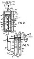
- the air duct 7 is replaced by a conventional air fan compartment 7a ( Figure 2) with an air fan unit 7b for providing the equivalent of air stream 11. Steam exits from the enclosure compartment 7a via a steam distributor 7c.
- the forced draft combustion system includes the previously mentioned combustion controller 10 that controls ignition and flame of the forced draft burner 13, and a combination gas valve 14, the forced draft fan 16, and a flue discharge duct 5.
- the combination gas valve 14 may be a proportional solenoid valve when using a modulation humidistat, or an ON-OFF type solenoid valve for use with an ON-OFF or a time proportioning type humidistat. To improve the combustion efficiency the proportional gas valve 14 may be replaced by a modulating constant air/fuel ratio valve train (not shown in Fig. 1). An induced draft combustion system replacing the described forced draft combustion system could be used.
- the water tank unit 3 is a scaled, i.e. closed water tank of a corrosion resistant material such as stainless steel and of a rectangular shape designed for operating at substantially atmospheric pressure. As an example, the capacity of the tank is 85 kilograms of water.
- the water tank 3 has respective outer major side walls 3a, 3b, a top wall 3c, a bottom wall 3d and end walls 3e, 3f.
- Top wall 3c is removably attached as by threaded fasteners 3g or other suitable means. This allows for periodically cleaning out the tank.
- the tank is completely surrounded by insulation 29 and as seen in Figure 1, the tank unit is contained in an outer housing H1.
- the water tank, and walls defining the combustion chamber and heat exchanger chamber are constructed and/or so arranged such that the water in the tank completely or essentially completely surrounds the combustion chamber and heat exchanger.
- the bottom wall 3d is separated into two spaced apart portions by upwardly directed water tank inner side walls 26a and 26b which are joined at their upper end by a top end wall 26c. These latter walls together with end walls 3e, 3f define the combustion chamber 4 and the chamber of the heat exchanger 2.
- the combustion chamber 4 is closed on the bottom by the insulated bottom wall of the outer casing or housing H1.
- FIG 5 illustrates an alternative construction where the combustion chamber has a bottom wall 26d which is spaced upwardly from the water tank bottom wall 3d.
- the combustion chamber and heat exchanger chamber are closed at the end by respective end walls 26e and 26f. These latter walls are spaced from the water tank respective end walls 3e and 3f and maintained in spaced relation therewith by spacers S.
- the bottom wall 26d of the combustion chamber rests on one or more saddles 5a. From this it is evident the heat exchanger chamber and combustion chamber in the lower portion thereof is completely immersed in water when the tank is filled to its predetermined operative level which during operation varies between a high level 41a and a low level 41b (see Figure 3).
- Water is supplied to the tank through a feed water solenoid valve 18 that is interconnected with a water level controller 50 and a variable timer 47 actuated by float controlled switches 51, 52. These control the flow of feed water and the water level of the boiling water in the water tank.
- the float control switches could be replaced by a level control unit 49 (shown in broken line in Figure 3) having three probes that are activated by contact with the water surface.
- the level sensing means may be located either in the main water tank or in an external chamber as shown.
- An overflow skimmer pipe 19 protects the water tank from overfilling.
- a feed water discharge outlet 23 is located so that the water therefrom discharge into the evaporative chamber 21.
- An outlet 24 is provided for the discharge of steam 12 via conduit means 44 to the steam distributor 6 and it also provides for condensate return via conduit 45.
- the overflow skimmer conduit 19 discharges into a drain 43 through a water seal 25.
- the flow restrictor 40 is provided for controlling the flow rate of feed water and this along vith solenoid valve 18, controller 50 and float switches 51 and 52 maintains the water in water tank 3 between the predetermined high and low water levels designated respectively 41a and 41b ( Figure 3).
- a manual drain valve 42 is provided for the seasonal draining of the water tank 3 via drain pipe 43 to a common sewer line.
- the steam distributor 6 is a conduit with apertures or nozzles for distribution of the steam 12 into the air stream 11 passing through the air duct 7.
- the steam is delivered to the distributor 6 from outlet 24 via a steam pipe 44 and the condensate is returned via pipe 45.
- the water tank 3 has thermal insulation 29 on all surfaces thereon to minimize heat loss from the hot water for improved efficiency and reduced time to the start of steam production.
- a gaseous fuel 31 mixes with combustion air 32 in the forced draft fan 16. This mixture goes to the burner 13 and combustion is controlled by controller 10. Flow of the fuel 31 is regulated by the gas valve 14 controlled by the humidistat 1 through combustion controller 10 and flow of the combustion air 32 is regulated by the forced draft fan 16 which is also controlled by controller 10.
- the major portion of the heat from combustion of fuel is transferred from the combustion gases 30 to the water while the gases pass through the combustion chamber 4 and heat exchanger 2.
- the heat transfer to the water is through the two side walls 26a, 26b and top 26c of the heat exchanger ( Figures 2,3).
- the heat exchanger 2 contains a baffle means 15 that improves the heat transfer to the heat exchanger walls 26a and 26b.
- the two walls 26a, and 26b, of the heat exchanger that are in contact with the hot combustion gases may also be corrugated or provided with fins to further increase the heat transfer rate into the water in the tank.
- Baffle means 15 may be variously designed for maximizing heat transfer from the combustion gases to the water in the tank.
- a baffle is arranged to provide a primary zig-zag flow path represented in Figure 4 by arrows A1, and a secondary or leakage flow path represented by arrows A2 in Figure 5.
- the flow paths A1 are effectively parallel horizontal flow paths that are in series by virtue of openings A4 at one end of alternate ones of the baffle flat surfaces and openings A5 at alternate ones of the remaining flat surfaces of the baffles.
- the water tank 3, exhaust fan 16, and the flue discharge duct 5 are protected against overheating by a high temperature limit control switch 34 located near the exit of the heat exchanger in the flue discharge duct 5 and suitably connected to deactivate the system upon reaching an overheat situation. Further overheat protection is provided by a low water level float switch 53 suitably connected to deactivate the system upon reaching an abnormally low water level in the water tank 3. It can be appreciated, that if desired, the described gaseous fuel may be conveniently replaced by a liquid fuel to achieve the same result.
- a monitor not shown, including sensors, processors, clock, timer, and displays may be provided to monitor and display the performance and operation of the humidifying system.
- the modulating humidistat 1 continuously monitory the humidity load demand of the air 11 in air duct 7 and through combustion controller 10 regulates the operation of the burner 13 and of the proportional gas solenoid valve 14.
- the required combustion air 32 is forced through the burner by the forced draft fan 16.
- Combustion of the gaseous fuel 31 with combustion air 32 occurs at the burner 13 in the combustion chamber 4.
- Combustion of the fuel produces the process heat required for heating the water 37 to boiling temperature and for production of the required amount of steam 12 to be added to the air stream 11 in the air duct 7 through the steam distributor 6.
- the required process heat is recovered and transferred from the hot combustion gases 30, passing through oombustion chamber 4 into and through the heat exchanger walls 26a, and 26b, into the water 37 causing it to boil.
- the flue gases cool as they are forced through the combustion chamber 4 and heat exchanger 2 by the forced draft fan 16 and are discharged via the duct 5 to outdoors.
- the steam for humidification is produced in a cyclic evaporation process controlled by the modulating humidistat and carried out in water tank 3 at substantially atmospheric pressure in three operating periods.
- the first operating period involves the process steps of a continuous combustion of fuel and transfer of heat from combustion gases to boiling water, the evaporation of boiling water, separation of the produced steam from the boiling water, concentration of dissolved solids in the boiling water, and discharge of the produced steam out of the water tank.
- concentration of the TDS (total dissolved solids) in the boiling water rises and the water level in the water tank slowly drops from the high water level point 41a to the low point 41b.
- concentration of TDS in the boiling water increases in proportion to the volume of the water evaporated between the two water level points.
- the water level float switch 52 activates the feed water solenoid valve 18 to permit a controlled flow of feed water through the flow restrictor 40 into the water tank 3. Opening of the feed water solenoid valve starts the second operating period of the steam generation process cycle.
- the second operating period involves the process steps of a continuous flow of incoming feed water, a continuous combustion of fuel and transfer of heat from combustion gases to boiling water, separation of the produced steam from the boiling water, dilution of the TDS in the boiling water, and discharge of the produced steam out of the water tank.
- the heat transferred to the boiling water is used to heat the feed water to its boiling temperature and to produce the required steam.
- the capacity to produce steam is reduced by the amount of heat used up in heating of the feed water to its boiling temperature.
- the flow rate of feed water is limited by restrictor 40. Due to the incoming feed water, concentration of TDS in the boiling water drops.
- the high water level switch 51 activates a variable timer 47. This initiates the third operating period of the steam process cycle.
- the third is similar to the second, with the continuous flow of incoming feed water causing the level of the water in the tank to continue to rise until the level reaches an overflow skimmer pipe 19.
- the top edge of this skimmer 19 is located slightly above the high water level point 41a. Water flows out the overflow skimmer to drain for a predetermined time period, dependent on the known TDS concentration of the feed water, to reduce the TDS concentration of the water in the water tank. The end of the timed period deactivates the feed water solenoid valve 18 to complete the third operating period of the steam process cycle and start a new cycle.
- concentration of the hard scale forming substances in the boiling water is maintained within their solubility limits with minimum overflow (blowdown) of the concentrated boiling water.
- FIG. 3 An alternate method of controlling the amount of overflow water is shown in Figure 3.
- the upper edge of the overflow skimmer 19 is located slightly below the high water level 41a.
- water flows into the skimmer 19 and fills a fixed volume blowdown chamber 27.
- the high water float control deactivates the feed water solenoid and activates a solenoid drain valve 46 to allow the water in the blowdown chamber 27 to flow through a strainer 28, and through the solenoid drain valve to drain 43, to end the cycle.
- the tank providing blow down chamber 27 is vented to atmosphere by vent pipe 27a.
- the boiling blowdown water may flow through a heat exchanger to preheat the incoming feed water to improve efficiency and also decrease the temperature of the drain water.
- the incoming feed water may be made to pass through a feedwater preheater, not shown, which may be of the storage type.
- the required heat for the feedwater preheater would be recovered and transferred from the hot combustion gases 30. This would improve efficiency and reduce the reduction in steam output caused by introducing cold feedwater.
- Combustion air 32 may be ducted from outside the building envelope by connecting a duct (not shown) to the forced draft fan 16.
- the water tank and combustion chamber have large smooth surfaces with no hidden areas as would be unavoidable with a tubular heat exchanger design.
- the output could be increased by an appropriate sized water tank perhaps 6 inches wider to accommodate a second combustion chamber/heat exchanger in the same water tank.
- a second system of gas controls and blower could operate independent of the first one so that one or the other or both burners could be operational at the same time. The operational advantage is that one of the burner systems could be shut off to achieve a lower output when required.
- two or more burners can be located in a single combustion chamber/heat exchanger unit. Suitable operational controls may be provided for operating one or the other burners for lower outputs or both at the same time for maximum output.
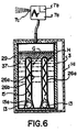
- each combustion chamber/heat exchanger chamber and burner is a modular unit and the same as that described previously with reference to Figure 5 or Figures 2 and 3.
Landscapes
- Engineering & Computer Science (AREA)
- Chemical & Material Sciences (AREA)
- Combustion & Propulsion (AREA)
- Mechanical Engineering (AREA)
- General Engineering & Computer Science (AREA)
- Physics & Mathematics (AREA)
- Thermal Sciences (AREA)
- Air Humidification (AREA)
- Glass Compositions (AREA)
Applications Claiming Priority (2)
| Application Number | Priority Date | Filing Date | Title |
|---|---|---|---|
| US637394 | 1996-04-25 | ||
| US08/637,394 US5816496A (en) | 1996-04-25 | 1996-04-25 | Gas fired humidifier |
Publications (3)
| Publication Number | Publication Date |
|---|---|
| EP0803686A2 true EP0803686A2 (fr) | 1997-10-29 |
| EP0803686A3 EP0803686A3 (fr) | 2000-03-01 |
| EP0803686B1 EP0803686B1 (fr) | 2004-07-07 |
Family
ID=24555731
Family Applications (1)
| Application Number | Title | Priority Date | Filing Date |
|---|---|---|---|
| EP97302816A Expired - Lifetime EP0803686B1 (fr) | 1996-04-25 | 1997-04-24 | Humidificateur d'air fonctionnant au gaz |
Country Status (5)
| Country | Link |
|---|---|
| US (1) | US5816496A (fr) |
| EP (1) | EP0803686B1 (fr) |
| AT (1) | ATE270762T1 (fr) |
| CA (1) | CA2203332C (fr) |
| DE (1) | DE69729766T8 (fr) |
Families Citing this family (17)
| Publication number | Priority date | Publication date | Assignee | Title |
|---|---|---|---|---|
| US6070559A (en) * | 1999-05-21 | 2000-06-06 | Armstrong International, Inc. | Annular tube heat exchanger |
| US6446877B1 (en) | 2000-11-08 | 2002-09-10 | Armstrong International, Incorporated | Gas fired humidifier |
| US6705535B1 (en) * | 2003-04-29 | 2004-03-16 | Pure Humidifier Co. | Side entry humidifier |
| GB0315873D0 (en) * | 2003-07-07 | 2003-08-13 | Eaton Williams Group Ltd | A humidification system |
| US7011300B2 (en) * | 2003-10-02 | 2006-03-14 | National Environmental Products, Ltd. | Steam humidifier and method |
| US7112770B2 (en) * | 2003-10-03 | 2006-09-26 | The Boeing Company | Humidification system and method for a mobile platform |
| US6945197B2 (en) * | 2003-12-29 | 2005-09-20 | Grand Hall Enterprise Co., Ltd. | Water heater |
| US7954459B2 (en) * | 2007-06-27 | 2011-06-07 | The Boeing Company | Method and apparatus for vaporizing liquid |
| US20120180996A1 (en) * | 2011-01-19 | 2012-07-19 | Chadwick Energy Services Ltd. | Jacketed firetube system for a process vessel |
| DE102011114900B4 (de) * | 2011-10-05 | 2015-08-27 | Thermo Electron Led Gmbh | Brutschrank mit verbesserter innenraum-befeuchtung |
| US20140245972A1 (en) * | 2013-02-12 | 2014-09-04 | Lester James Thiessen | Heat Exchanger for an Oil Storage Tank |
| CN106288103A (zh) * | 2015-06-09 | 2017-01-04 | 鸿富锦精密工业(武汉)有限公司 | 具加湿功能的电子装置 |
| CA3037172C (fr) * | 2016-06-13 | 2020-06-23 | Condair Group Ag | Methodes et systemes destines a un humidificateur a deux etages |
| TW201839333A (zh) * | 2017-04-28 | 2018-11-01 | 盈太企業股份有限公司 | 蒸氣產生裝置與蒸氣清潔設備 |
| CA3089000A1 (fr) | 2018-01-19 | 2019-07-25 | Dri-Steem Corporation | Humidificateur avec determination automatique d'intervalle de vidange |
| EP3740715B1 (fr) * | 2018-01-19 | 2023-12-20 | DRI-Steem Corporation | Humidificateur à condensation alimenté au gaz présentant une émission ultra-faible de nox |
| CN110749017A (zh) * | 2019-12-09 | 2020-02-04 | 佛山市顺德区雅洛特电器有限公司 | 顶置式上加水加湿器 |
Family Cites Families (12)
| Publication number | Priority date | Publication date | Assignee | Title |
|---|---|---|---|---|
| US2169683A (en) * | 1938-01-03 | 1939-08-15 | Ex Lab Inc | Generating mixed fluid heating medium |
| GB735964A (en) * | 1952-05-26 | 1955-08-31 | Heurtey & Cie | Heating device for liquid in a tank or for other purposes |
| US3824985A (en) * | 1972-05-01 | 1974-07-23 | S Hetherington | Humidifier |
| US4474117A (en) * | 1981-04-28 | 1984-10-02 | Paul Marollaud | Boiler using a solid granulated fuel |
| US4672919A (en) * | 1985-06-07 | 1987-06-16 | Bradford-White Corporation | Direct power vented water heater |
| US4697735A (en) * | 1986-06-27 | 1987-10-06 | John Temple | Humidifying hot water heater |
| US5067473A (en) * | 1989-07-19 | 1991-11-26 | Samsung Electronics Co., Ltd. | Heater with a humidifier |
| US5215043A (en) * | 1991-02-19 | 1993-06-01 | Mitsui Mining Company, Ltd. | Steam generator for a steam bath |
| WO1994010511A1 (fr) * | 1992-10-30 | 1994-05-11 | Li, Xiaoli | Systeme et procede de chauffage d'un liquide |
| US5355841A (en) * | 1993-08-27 | 1994-10-18 | Sabh (U.S.) Water Heater Group, Inc. | Water heater with integral burner |
| US5422976A (en) * | 1994-04-06 | 1995-06-06 | Bunn-O-Matic Corporation | Boiler control system with steam sensor thermally isolated from a water reservoir |
| US5544625A (en) * | 1995-06-20 | 1996-08-13 | Giant Factories Inc. | Flue baffle for gas-fired hot water tanks |
-
1996
- 1996-04-25 US US08/637,394 patent/US5816496A/en not_active Expired - Lifetime
-
1997
- 1997-04-22 CA CA002203332A patent/CA2203332C/fr not_active Expired - Lifetime
- 1997-04-24 DE DE69729766T patent/DE69729766T8/de active Active
- 1997-04-24 EP EP97302816A patent/EP0803686B1/fr not_active Expired - Lifetime
- 1997-04-24 AT AT97302816T patent/ATE270762T1/de not_active IP Right Cessation
Also Published As
| Publication number | Publication date |
|---|---|
| EP0803686A3 (fr) | 2000-03-01 |
| EP0803686B1 (fr) | 2004-07-07 |
| DE69729766D1 (de) | 2004-08-12 |
| DE69729766T8 (de) | 2005-11-17 |
| DE69729766T2 (de) | 2005-07-14 |
| US5816496A (en) | 1998-10-06 |
| ATE270762T1 (de) | 2004-07-15 |
| CA2203332C (fr) | 2002-07-02 |
| CA2203332A1 (fr) | 1997-10-25 |
Similar Documents
| Publication | Publication Date | Title |
|---|---|---|
| EP0803686B1 (fr) | Humidificateur d'air fonctionnant au gaz | |
| CA1219545A (fr) | Appareil de chauffage et de distillation de l'eau | |
| US7281498B2 (en) | Compact high efficiency gas fired steam generator-humidifier | |
| CA2262990C (fr) | Dispositif pour le chauffage reglable de fluides de traitement | |
| US20210348779A1 (en) | Heat exchanger for removal of condensate from a steam dispersion system | |
| US4678116A (en) | Water heater | |
| US6397788B2 (en) | Compact ultra high efficiency gas fired steam generator | |
| EP0138319B1 (fr) | Appareil de chauffage de l'eau chauffé par gaz | |
| DK162952B (da) | Apparat til forbraending af en braendbar gas | |
| JPS61116247A (ja) | 改良ガス燃焼式温水器 | |
| CA2524909A1 (fr) | Humidificateur de gaz et procede de regulation de la temperature du gaz | |
| US5765546A (en) | Direct contact water heater with dual water heating chambers | |
| HU217110B (hu) | Közvetlen érintkezésű, gázfűtéses vízmelegítő berendezés | |
| US4203300A (en) | Horizontal direct fired water bath propane vaporizer | |
| US3308805A (en) | Heating and air conditioning apparatus | |
| US6305612B1 (en) | Compact gas fired humidifier | |
| EP0246376A1 (fr) | Dispositif de chauffage et de distillation de l'eau | |
| RU2236650C1 (ru) | Контактный водонагреватель | |
| CA2295379A1 (fr) | Humidificateur a gaz compact | |
| RU2680458C1 (ru) | Контактный водонагреватель | |
| US2244126A (en) | Humidifier | |
| GB2057102A (en) | Method and apparatus for generating vapour | |
| JP7837213B2 (ja) | 熱源装置 | |
| SU1384877A1 (ru) | Котел | |
| WO2000068622A1 (fr) | Appareil frigorifique a absorption |
Legal Events
| Date | Code | Title | Description |
|---|---|---|---|
| PUAI | Public reference made under article 153(3) epc to a published international application that has entered the european phase |
Free format text: ORIGINAL CODE: 0009012 |
|
| AK | Designated contracting states |
Kind code of ref document: A2 Designated state(s): AT BE CH DE DK ES FI FR GB GR IE IT LI LU MC NL PT SE |
|
| AX | Request for extension of the european patent |
Free format text: AL PAYMENT 970505;LT PAYMENT 970505;LV PAYMENT 970505;RO PAYMENT 970505;SI PAYMENT 970505 |
|
| RHK1 | Main classification (correction) |
Ipc: F24F 6/18 |
|
| 17P | Request for examination filed |
Effective date: 19990504 |
|
| PUAL | Search report despatched |
Free format text: ORIGINAL CODE: 0009013 |
|
| AK | Designated contracting states |
Kind code of ref document: A3 Designated state(s): AT BE CH DE DK ES FI FR GB GR IE IT LI LU MC NL PT SE |
|
| AX | Request for extension of the european patent |
Free format text: AL PAYMENT 19970505;LT PAYMENT 19970505;LV PAYMENT 19970505;RO PAYMENT 19970505;SI PAYMENT 19970505 |
|
| 17Q | First examination report despatched |
Effective date: 20010824 |
|
| GRAP | Despatch of communication of intention to grant a patent |
Free format text: ORIGINAL CODE: EPIDOSNIGR1 |
|
| GRAS | Grant fee paid |
Free format text: ORIGINAL CODE: EPIDOSNIGR3 |
|
| GRAA | (expected) grant |
Free format text: ORIGINAL CODE: 0009210 |
|
| AK | Designated contracting states |
Kind code of ref document: B1 Designated state(s): AT BE CH DE DK ES FI FR GB GR IE IT LI LU MC NL PT SE |
|
| AX | Request for extension of the european patent |
Extension state: AL LT LV RO SI |
|
| PG25 | Lapsed in a contracting state [announced via postgrant information from national office to epo] |
Ref country code: LI Free format text: LAPSE BECAUSE OF FAILURE TO SUBMIT A TRANSLATION OF THE DESCRIPTION OR TO PAY THE FEE WITHIN THE PRESCRIBED TIME-LIMIT Effective date: 20040707 Ref country code: IT Free format text: LAPSE BECAUSE OF FAILURE TO SUBMIT A TRANSLATION OF THE DESCRIPTION OR TO PAY THE FEE WITHIN THE PRESCRIBED TIME-LIMIT;WARNING: LAPSES OF ITALIAN PATENTS WITH EFFECTIVE DATE BEFORE 2007 MAY HAVE OCCURRED AT ANY TIME BEFORE 2007. THE CORRECT EFFECTIVE DATE MAY BE DIFFERENT FROM THE ONE RECORDED. Effective date: 20040707 Ref country code: FR Free format text: LAPSE BECAUSE OF FAILURE TO SUBMIT A TRANSLATION OF THE DESCRIPTION OR TO PAY THE FEE WITHIN THE PRESCRIBED TIME-LIMIT Effective date: 20040707 Ref country code: FI Free format text: LAPSE BECAUSE OF FAILURE TO SUBMIT A TRANSLATION OF THE DESCRIPTION OR TO PAY THE FEE WITHIN THE PRESCRIBED TIME-LIMIT Effective date: 20040707 Ref country code: CH Free format text: LAPSE BECAUSE OF FAILURE TO SUBMIT A TRANSLATION OF THE DESCRIPTION OR TO PAY THE FEE WITHIN THE PRESCRIBED TIME-LIMIT Effective date: 20040707 Ref country code: BE Free format text: LAPSE BECAUSE OF FAILURE TO SUBMIT A TRANSLATION OF THE DESCRIPTION OR TO PAY THE FEE WITHIN THE PRESCRIBED TIME-LIMIT Effective date: 20040707 Ref country code: AT Free format text: LAPSE BECAUSE OF FAILURE TO SUBMIT A TRANSLATION OF THE DESCRIPTION OR TO PAY THE FEE WITHIN THE PRESCRIBED TIME-LIMIT Effective date: 20040707 |
|
| REG | Reference to a national code |
Ref country code: GB Ref legal event code: FG4D |
|
| REG | Reference to a national code |
Ref country code: CH Ref legal event code: EP |
|
| REG | Reference to a national code |
Ref country code: IE Ref legal event code: FG4D |
|
| REF | Corresponds to: |
Ref document number: 69729766 Country of ref document: DE Date of ref document: 20040812 Kind code of ref document: P |
|
| PG25 | Lapsed in a contracting state [announced via postgrant information from national office to epo] |
Ref country code: SE Free format text: LAPSE BECAUSE OF FAILURE TO SUBMIT A TRANSLATION OF THE DESCRIPTION OR TO PAY THE FEE WITHIN THE PRESCRIBED TIME-LIMIT Effective date: 20041007 Ref country code: GR Free format text: LAPSE BECAUSE OF FAILURE TO SUBMIT A TRANSLATION OF THE DESCRIPTION OR TO PAY THE FEE WITHIN THE PRESCRIBED TIME-LIMIT Effective date: 20041007 Ref country code: DK Free format text: LAPSE BECAUSE OF FAILURE TO SUBMIT A TRANSLATION OF THE DESCRIPTION OR TO PAY THE FEE WITHIN THE PRESCRIBED TIME-LIMIT Effective date: 20041007 |
|
| PG25 | Lapsed in a contracting state [announced via postgrant information from national office to epo] |
Ref country code: ES Free format text: LAPSE BECAUSE OF FAILURE TO SUBMIT A TRANSLATION OF THE DESCRIPTION OR TO PAY THE FEE WITHIN THE PRESCRIBED TIME-LIMIT Effective date: 20041018 |
|
| LTIE | Lt: invalidation of european patent or patent extension |
Effective date: 20040707 |
|
| REG | Reference to a national code |
Ref country code: CH Ref legal event code: PL |
|
| PG25 | Lapsed in a contracting state [announced via postgrant information from national office to epo] |
Ref country code: LU Free format text: LAPSE BECAUSE OF NON-PAYMENT OF DUE FEES Effective date: 20050424 |
|
| PG25 | Lapsed in a contracting state [announced via postgrant information from national office to epo] |
Ref country code: IE Free format text: LAPSE BECAUSE OF NON-PAYMENT OF DUE FEES Effective date: 20050425 |
|
| PG25 | Lapsed in a contracting state [announced via postgrant information from national office to epo] |
Ref country code: MC Free format text: LAPSE BECAUSE OF NON-PAYMENT OF DUE FEES Effective date: 20050430 |
|
| PLBE | No opposition filed within time limit |
Free format text: ORIGINAL CODE: 0009261 |
|
| STAA | Information on the status of an ep patent application or granted ep patent |
Free format text: STATUS: NO OPPOSITION FILED WITHIN TIME LIMIT |
|
| 26N | No opposition filed |
Effective date: 20050408 |
|
| EN | Fr: translation not filed | ||
| NLT1 | Nl: modifications of names registered in virtue of documents presented to the patent office pursuant to art. 16 a, paragraph 1 |
Owner name: AXAIR NORTEC LTD. |
|
| PG25 | Lapsed in a contracting state [announced via postgrant information from national office to epo] |
Ref country code: PT Free format text: LAPSE BECAUSE OF NON-PAYMENT OF DUE FEES Effective date: 20041207 |
|
| NLT1 | Nl: modifications of names registered in virtue of documents presented to the patent office pursuant to art. 16 a, paragraph 1 |
Owner name: WALTER MEIER (CLIMATE CANADA) LTD. |
|
| REG | Reference to a national code |
Ref country code: NL Ref legal event code: TD Effective date: 20120704 |
|
| REG | Reference to a national code |
Ref country code: DE Ref legal event code: R082 Ref document number: 69729766 Country of ref document: DE Representative=s name: WINTER, BRANDL, FUERNISS, HUEBNER, ROESS, KAIS, DE Effective date: 20120802 Ref country code: DE Ref legal event code: R081 Ref document number: 69729766 Country of ref document: DE Owner name: NORTEC HUMIDITY LTD., CA Free format text: FORMER OWNER: WALTER MEIER (CLIMATE CANADA) LTD., OTTAWA, ONTARIA, CA Effective date: 20120802 Ref country code: DE Ref legal event code: R081 Ref document number: 69729766 Country of ref document: DE Owner name: NORTEC HUMIDITY LTD., CA Free format text: FORMER OWNER: WALTER MEIER (CLIMATE CANADA) LTD., OTTAWA, CA Effective date: 20120802 |
|
| PGFP | Annual fee paid to national office [announced via postgrant information from national office to epo] |
Ref country code: GB Payment date: 20160303 Year of fee payment: 20 |
|
| PGFP | Annual fee paid to national office [announced via postgrant information from national office to epo] |
Ref country code: NL Payment date: 20160420 Year of fee payment: 20 |
|
| PGFP | Annual fee paid to national office [announced via postgrant information from national office to epo] |
Ref country code: DE Payment date: 20160421 Year of fee payment: 20 |
|
| REG | Reference to a national code |
Ref country code: DE Ref legal event code: R071 Ref document number: 69729766 Country of ref document: DE |
|
| REG | Reference to a national code |
Ref country code: NL Ref legal event code: MK Effective date: 20170423 |
|
| REG | Reference to a national code |
Ref country code: GB Ref legal event code: PE20 Expiry date: 20170423 |
|
| PG25 | Lapsed in a contracting state [announced via postgrant information from national office to epo] |
Ref country code: GB Free format text: LAPSE BECAUSE OF EXPIRATION OF PROTECTION Effective date: 20170423 |