EP0803669A2 - Fluid pressure relief system for pressure vessels - Google Patents
Fluid pressure relief system for pressure vessels Download PDFInfo
- Publication number
- EP0803669A2 EP0803669A2 EP97111757A EP97111757A EP0803669A2 EP 0803669 A2 EP0803669 A2 EP 0803669A2 EP 97111757 A EP97111757 A EP 97111757A EP 97111757 A EP97111757 A EP 97111757A EP 0803669 A2 EP0803669 A2 EP 0803669A2
- Authority
- EP
- European Patent Office
- Prior art keywords
- fluid
- valve
- chamber
- pressure
- valve member
- Prior art date
- Legal status (The legal status is an assumption and is not a legal conclusion. Google has not performed a legal analysis and makes no representation as to the accuracy of the status listed.)
- Withdrawn
Links
Images


Classifications
-
- F—MECHANICAL ENGINEERING; LIGHTING; HEATING; WEAPONS; BLASTING
- F16—ENGINEERING ELEMENTS AND UNITS; GENERAL MEASURES FOR PRODUCING AND MAINTAINING EFFECTIVE FUNCTIONING OF MACHINES OR INSTALLATIONS; THERMAL INSULATION IN GENERAL
- F16K—VALVES; TAPS; COCKS; ACTUATING-FLOATS; DEVICES FOR VENTING OR AERATING
- F16K17/00—Safety valves; Equalising valves, e.g. pressure relief valves
- F16K17/02—Safety valves; Equalising valves, e.g. pressure relief valves opening on surplus pressure on one side; closing on insufficient pressure on one side
- F16K17/04—Safety valves; Equalising valves, e.g. pressure relief valves opening on surplus pressure on one side; closing on insufficient pressure on one side spring-loaded
- F16K17/10—Safety valves; Equalising valves, e.g. pressure relief valves opening on surplus pressure on one side; closing on insufficient pressure on one side spring-loaded with auxiliary valve for fluid operation of the main valve
-
- F—MECHANICAL ENGINEERING; LIGHTING; HEATING; WEAPONS; BLASTING
- F16—ENGINEERING ELEMENTS AND UNITS; GENERAL MEASURES FOR PRODUCING AND MAINTAINING EFFECTIVE FUNCTIONING OF MACHINES OR INSTALLATIONS; THERMAL INSULATION IN GENERAL
- F16K—VALVES; TAPS; COCKS; ACTUATING-FLOATS; DEVICES FOR VENTING OR AERATING
- F16K17/00—Safety valves; Equalising valves, e.g. pressure relief valves
- F16K17/18—Safety valves; Equalising valves, e.g. pressure relief valves opening on surplus pressure on either side
- F16K17/19—Equalising valves predominantly for tanks
- F16K17/194—Equalising valves predominantly for tanks weight-loaded
-
- F—MECHANICAL ENGINEERING; LIGHTING; HEATING; WEAPONS; BLASTING
- F16—ENGINEERING ELEMENTS AND UNITS; GENERAL MEASURES FOR PRODUCING AND MAINTAINING EFFECTIVE FUNCTIONING OF MACHINES OR INSTALLATIONS; THERMAL INSULATION IN GENERAL
- F16K—VALVES; TAPS; COCKS; ACTUATING-FLOATS; DEVICES FOR VENTING OR AERATING
- F16K17/00—Safety valves; Equalising valves, e.g. pressure relief valves
- F16K17/18—Safety valves; Equalising valves, e.g. pressure relief valves opening on surplus pressure on either side
- F16K17/19—Equalising valves predominantly for tanks
- F16K17/196—Equalising valves predominantly for tanks spring-loaded
-
- Y—GENERAL TAGGING OF NEW TECHNOLOGICAL DEVELOPMENTS; GENERAL TAGGING OF CROSS-SECTIONAL TECHNOLOGIES SPANNING OVER SEVERAL SECTIONS OF THE IPC; TECHNICAL SUBJECTS COVERED BY FORMER USPC CROSS-REFERENCE ART COLLECTIONS [XRACs] AND DIGESTS
- Y10—TECHNICAL SUBJECTS COVERED BY FORMER USPC
- Y10T—TECHNICAL SUBJECTS COVERED BY FORMER US CLASSIFICATION
- Y10T137/00—Fluid handling
- Y10T137/0318—Processes
- Y10T137/0324—With control of flow by a condition or characteristic of a fluid
- Y10T137/0379—By fluid pressure
-
- Y—GENERAL TAGGING OF NEW TECHNOLOGICAL DEVELOPMENTS; GENERAL TAGGING OF CROSS-SECTIONAL TECHNOLOGIES SPANNING OVER SEVERAL SECTIONS OF THE IPC; TECHNICAL SUBJECTS COVERED BY FORMER USPC CROSS-REFERENCE ART COLLECTIONS [XRACs] AND DIGESTS
- Y10—TECHNICAL SUBJECTS COVERED BY FORMER USPC
- Y10T—TECHNICAL SUBJECTS COVERED BY FORMER US CLASSIFICATION
- Y10T137/00—Fluid handling
- Y10T137/7722—Line condition change responsive valves
- Y10T137/7738—Pop valves
-
- Y—GENERAL TAGGING OF NEW TECHNOLOGICAL DEVELOPMENTS; GENERAL TAGGING OF CROSS-SECTIONAL TECHNOLOGIES SPANNING OVER SEVERAL SECTIONS OF THE IPC; TECHNICAL SUBJECTS COVERED BY FORMER USPC CROSS-REFERENCE ART COLLECTIONS [XRACs] AND DIGESTS
- Y10—TECHNICAL SUBJECTS COVERED BY FORMER USPC
- Y10T—TECHNICAL SUBJECTS COVERED BY FORMER US CLASSIFICATION
- Y10T137/00—Fluid handling
- Y10T137/7722—Line condition change responsive valves
- Y10T137/7758—Pilot or servo controlled
- Y10T137/7762—Fluid pressure type
- Y10T137/7764—Choked or throttled pressure type
-
- Y—GENERAL TAGGING OF NEW TECHNOLOGICAL DEVELOPMENTS; GENERAL TAGGING OF CROSS-SECTIONAL TECHNOLOGIES SPANNING OVER SEVERAL SECTIONS OF THE IPC; TECHNICAL SUBJECTS COVERED BY FORMER USPC CROSS-REFERENCE ART COLLECTIONS [XRACs] AND DIGESTS
- Y10—TECHNICAL SUBJECTS COVERED BY FORMER USPC
- Y10T—TECHNICAL SUBJECTS COVERED BY FORMER US CLASSIFICATION
- Y10T137/00—Fluid handling
- Y10T137/7722—Line condition change responsive valves
- Y10T137/7781—With separate connected fluid reactor surface
- Y10T137/7832—Plural valves biased closed
-
- Y—GENERAL TAGGING OF NEW TECHNOLOGICAL DEVELOPMENTS; GENERAL TAGGING OF CROSS-SECTIONAL TECHNOLOGIES SPANNING OVER SEVERAL SECTIONS OF THE IPC; TECHNICAL SUBJECTS COVERED BY FORMER USPC CROSS-REFERENCE ART COLLECTIONS [XRACs] AND DIGESTS
- Y10—TECHNICAL SUBJECTS COVERED BY FORMER USPC
- Y10T—TECHNICAL SUBJECTS COVERED BY FORMER US CLASSIFICATION
- Y10T137/00—Fluid handling
- Y10T137/8593—Systems
- Y10T137/86292—System with plural openings, one a gas vent or access opening
- Y10T137/86324—Tank with gas vent and inlet or outlet
-
- Y—GENERAL TAGGING OF NEW TECHNOLOGICAL DEVELOPMENTS; GENERAL TAGGING OF CROSS-SECTIONAL TECHNOLOGIES SPANNING OVER SEVERAL SECTIONS OF THE IPC; TECHNICAL SUBJECTS COVERED BY FORMER USPC CROSS-REFERENCE ART COLLECTIONS [XRACs] AND DIGESTS
- Y10—TECHNICAL SUBJECTS COVERED BY FORMER USPC
- Y10T—TECHNICAL SUBJECTS COVERED BY FORMER US CLASSIFICATION
- Y10T137/00—Fluid handling
- Y10T137/8593—Systems
- Y10T137/86292—System with plural openings, one a gas vent or access opening
- Y10T137/8634—With vented outlet
Definitions
- main relief valve 25 will operate independently.
- Main valve member 66 will crack at a pressure over the set pressure of pilot valve 50 such as 110% of the set pressure and then move to a fully open position at a pressure of 120% of the set pressure of pilot valve 50.
- the 10% pressure band of valve member 66 from crack to full open position is provided by the additional lifting forces obtained from the partial restriction provided by shroud or upper housing 32 about valve member 66. Leakage at valve seat 64 at pressures below the set pressure of pilot valve 50 is prevented as a result of the residual seating load exerted by counterweight 74.
- Back pressure regulator valve 189B is similar in function to pilot 190B but is set to open at a higher fluid pressure than is valve 189B. Its purpose is to set an upper limit on the pressure in chamber 46B and to maintain that maximum value should regulator 185B fail to control the source pressure.
Landscapes
- Engineering & Computer Science (AREA)
- General Engineering & Computer Science (AREA)
- Mechanical Engineering (AREA)
- Safety Valves (AREA)
Abstract
Description
- This invention relates to a fluid pressure relief system for pressure vessels, such as tanks, and more particularly to such a fluid pressure relief system utilizing pilot operated relief valves and the method for providing the relief system.
- Heretofore, pilot operated relief valves have been utilized on pressure vessels, such as tanks, such as shown in U.S. Patent No. 4,705,065 dated November 10, 1987, for example, in the opening and closing of a main relief valve member and including the opening of the main valve member under a vacuum condition. However, the main relief valve has not functioned independently of the pilot valve such as may be necessary for a severe service and corrosion environment. The main valve member is in a fail open position in the event of any malfunctioning of the pilot valve.
- Present pilot operated relief valves can be operated at pressures very near the set pressure without leakage, and general seat tightness under all conditions is superior because of the high seating loads. Weighted and spring loaded relief valve members, however, are very simple and provide consistent reliability for users. Pilot valves which also provide excellent reliability, except under extreme service conditions, are more complex in operation but have superior performance.
- Pilot operated relief valves are particularly useful for low pressure vessels designed for a pressure under 15 psi. Such low pressure vessels are required to have: (1) a normal vent (usually small in orifice size) that limits the pressure rise due to either the addition of liquid to the vessel or the increase in vessel vapor space operating ambient temperature, (2) a normal breather (usually small in orifice size) that limits the vacuum on the vessel caused by removal of liquid from the vessel or a reduction in vessel vapor space operating ambient temperature, and (3) an emergency pressure vent (usually large in orifice size) that relieves the pressure in a vessel in the event the tank is subjected to fire or the like. Present code requirements for a low pressure vessel do not permit the setting of a valve above the maximum allowable working pressure (MAWP). Full relief capacity for the emergency vent may be at a pressure of 20% above the MAWP.
- Heretofore, pilot operated relief valves have been utilized with the normal vent of a pressure vessel and upon opening of the main valve member under control of the pilot, fluid vapors have normally been vented to atmosphere. Recent requirements of the Environmental Protection Agency (EPA) limit the leakage of harmful vapors from pressure vessels to a maximum concentration of 500 parts per million and these requirements have to be accomplished by December 31, 1992. Thus, it is necessary under certain conditions to collect the leakage of any harmful vapors from the pilot valve, particularly where the pilot valve is set to operate at a set pressure generally around 100% of the MAWP, for example, and this causes a relatively high frequency of operation of the pilot valve resulting in an opening of the main valve member for vapor leakage.
- The present invention is particularly directed to a fluid pressure relief system for pressure vessels having (1) a normal vent of a relatively small orifice size to limit a pressure increase resulting from the addition of liquid to the vessel or an increase in the ambient temperature in the vapor space, and (2) a separate emergency vent of a relatively large orifice size that relieves the pressure in the pressure vessel in the event of an emergency such as a fire. A pilot operated safety relief valve is utilized with the normal vent and a separate pilot operated safety relief valve is utilized with the emergency vent.
- The pilot operated safety relief valve for the emergency vent may be installed as a retrofit unit on the manway of a tank with the relief valve supported on the manway and extending within the tank from the manway. An emergency override is provided for opening of the main valve member in the event of any malfunctioning of the pilot valve.
- Also, a vacuum vent for the pressure vessel is provided to limit the vacuum on the pressure vessel resulting from removal of liquid from the vessel or a reduction in the operating ambient temperature in the vapor space of the pressure vessel. The vacuum vent and the emergency vent in the present invention communicate with the atmosphere when opened but these vents rarely open except in emergency conditions. However, the normal pressure vent is connected to a vapor recovery or collection device particularly in view of a low setting of the pilot valves relative to the MAWP generally around 98% of the MAWP, and a resulting high frequency of operation of the pilot valve.
- With the two functions being divided, (1) normal venting to a vapor recovery means, and (2) emergency venting and vacuum venting to the atmosphere, it is important to provide an efficient and effective system for these two functions as in the present invention. The hazardous chemicals in pressure vessels are potentially extremely corrosive. Since chloride compounds make up a major portion of these chemicals, the mixing of the chemicals with atmospheric moisture results in hydrochloric acid, which is destructive to practically all but the very expensive metals (such as Hastelloy). The chemicals inside the pressure vessel, however, are usually non-corrosive unless moisture is present in the system.
- A primary purpose of this invention is to provide a new and unique system for the control of vapor release or leakage from pressure vessels. The emergency vent normally operates only under fire conditions or in the event of failure of the normal vent to function and the vacuum protection is activated only if the inert gas system using nitrogen with a pressure control regulator should fail. However, because of potential fugitive emissions to atmosphere, the seats for the emergency and vacuum vents have to be of the highest sealing integrity since any leak becomes an atmospheric leak.
- It is an object of this invention to provide a fluid pressure relief system and a method for such system for a pressure vessel having a normal vent and a separate emergency vent with a separate pilot operated safety relief valve for each of the vents.
- Another object of this invention is to provide such a fluid pressure relief system in which a manway in the pressure vessel acts as a nozzle for the emergency vent, and a pilot operated relief valve mounted within and supported by the manway is operable upon a vacuum condition or emergency pressure condition.
- It is an additional object of this invention to provide a pilot operated relief valve which may be installed within the manway of an existing tank as a retrofit unit supported by the manway.
- It is a further object of this invention to provide such a fluid pressure relief system in which separate pilot operated relief valves are provided for a normal small diameter vent opening and an emergency large diameter vent opening with a vapor recovery device connected to the normal vent opening to collect vapor therefrom and prevent the escape of possible harmful vapors to atmosphere upon opening of the normal vent main valve member.
- It is another object of this invention to provide a pilot operated relief valve for the emergency vent opening in which the main valve member is capable of opening independently of the pilot valve thereby to provide reliability and operability in the event of possible malfunctioning of the pilot valve.
- A further object of this invention is to provide a fluid pressure relief system utilizing pilot operated relief valves for a pressure vessel designed for operating fluid pressures under 15 psi and providing an inert gas for the vacuum vent for the pressure vessel.
-
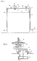
- Figure 1 is a generally schematic view of a fluid pressure relief system for a pressure vessel having a relatively small diameter normal vent and a large diameter emergency vent with a pilot operated relief valve for each of the vents;
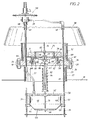
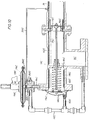
- Figure 2 is an enlarged sectional view of the pilot operated relief valve mounted on the manway of the pressure vessel which forms the large diameter emergency vent with the main valve member in closed seated position over the emergency vent;
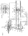
- Figure 3 is an enlarged cross sectional view of the pilot valve shown in Figure 2;
- Figure 4 is a section taken generally along line 4-4 of Figure 3; Figure 5 is an enlarged fragment of the pilot valve designated by
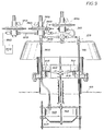
numeral 5 in Figure 3 showing the valve member in a seated position; - Figure 6 is a generally schematic sectional view of the pilot operated relief valve of Figure 2 but showing the main valve member in an open position under an emergency condition opening in response to the pilot valve;
- Figure 7 is an enlarged cross sectional view of an embodiment of a pilot operated relief valve for the small diameter normal vent of the pressure vessel;
- Figure 7A is an enlarged cross sectional view of the connection of the main valve member shown in the embodiment of Figure 7 to the valve stem;
- Figure 8 is a modified embodiment of a pilot operated relief valve for the normal vent in which a gas spring from an inert gas source applies a constant loading for seating of the main valve member;
- Figure 9 is a modified embodiment of a pilot operated relief valve for the emergency vent in which a separate inert gas source is provided to the diaphragm chamber for operation of the main valve member;
- Figure 10 is a modified embodiment of a pilot operated relief valve for the normal vent in which a spring is provided in the diaphragm chamber for seating of the main valve; and
- Figure 11 is a further modification of a relief valve for a normal vent which is adapted for opening under a vacuum condition and utilized as a very low pressure vacuum breaker with high integrity seats under positive pressure.
- Referring to Figure 1, a fluid pressure relief system in accordance with the present invention is illustrated generally schematically. A pressure vessel is shown generally at 10 and comprises a tank preferably having a liquid fluid stored therein with the liquid level shown at 12 and a
vapor space 14 in the tank above the liquid. - Oftentimes, chemicals are stored in the tank and various chlorine compounds which are hazardous and corrosive normally comprise a substantial portion of such chemicals.
- A normal vent for
tank 10 is shown at 16 and a pilot operated relief valve shown generally at 18 is mounted acrossvent 16. Pilot operatedrelief valve 18 has a set pressure at which to open and often the set pressure is only slightly below the maximum allowable working pressure (MAWP). Thus, the main valve member closing the vent opens with a high frequency and fluid vapors are normally emitted with each opening. Avapor recovery line 20 is connected torelief valve 18 and receives the vapor upon the opening of the main valve member. The emitted vapors (1) may be burned if inflammable from a flare stack, or (2) may be collected in a vapor storage chamber or container shown schematically at 21 and reprocessed for return topressure vessel 10 if desired. Thus, hazardous vapors are not emitted to the atmosphere. - Referring to Figure 2,
pressure vessel 10 has a manway generally indicated at 22 to permit a workman to enter the tank. Manway 22 includes a manway opening defined by atubular housing 23 at least around eighteen (18) inches in diameter projecting upwardly frompressure vessel 10 and generally forming an emergency vent.Housing 23 ofmanway 22 has an outwardly extendinghorizontal flange 24 and a separate pilot operated relief valve generally indicated at 25 is supported onflange 24 ofmanway 22 and may be installed as a retrofit unit onflange 24 of an existing tank by suitable nut andbolt combinations 26. Pilot operatedrelief valve 25 comprises an annular mounting plate orring 28 having a plurality of spacedopenings 30 for receiving nut andbolt combinations 26 for securingrelief valve 25 onflange 24. An upper housing orshroud 32 is secured to the upper surface ofannular plate 28. A plurality of rods orstruts 34 are secured by suitable fasteners toannular plate 28 and extend vertically therefrom. Anupper cover 38 is secured bynuts 40 to the extending upper ends ofrods 34 and aplate 42 is secured adjacent the lower ends ofrods 34.Fluid conduits ring 28 and cover 38 withconduit 37 also secured to plate 42. - A lower operating diaphragm is shown at 44 beneath
plate 42 and defining a domefluid pressure chamber 46 therebetween. Diaphragm 44 is gripped between aspacer 48 andlower ring 50 secured torods 34 andseparate rods 51.Conduit 37 forms a dome fluid conduit and provides fluid communication betweendome chamber 46 and adome port 48 to a pilot valve generally indicated at 50 and mounted oncover 38.Conduit 39 forms a fluid sensing conduit and has alower sensing port 56 in fluid communication with the interior oftank 10 and anupper inlet port 58 topilot valve 50. - Mounting
ring 28 has a separate innerconcentric nozzle ring 60 fitting within anotch 59 in mountingring 28 and defining a nozzle. Aretainer strip 61 is received within aslot 63 innozzle ring 60 and is secured to ring 28 to holdnozzle ring 60 in position. A suitable O-ring seal is provided betweennozzle ring 60 and mountingring 28.Nozzle ring 60 forms anemergency vent port 62 and an upperannular seat 64. A main pressure relief valve member generally indicated at 66 includes anouter seat ring 68 connected by ribs orspokes 70 to aninner hub 72.Seat ring 68 comprises an annular plate which extends radially outward ofnozzle ring 60 to provide an area exposed to fluid pressure upon opening ofrelief valve 66. Anannular counterweight 74 is mounted onseat ring 68 to maintainseat ring 68 in seated closed position onannular seat 64 under a predetermined constant loading withseat ring 68 moved upwardly to an unsealed open position at a predetermined fluid pressure withintank 10 above the maximum allowable working pressure. A limited flexure ofnozzle ring 60 relative to mounting plate may occur fromcounterweight 74. An operating shaft orrod 76 is secured tohub 72 ofvalve member 66 at 78 and to diaphragm 44 at 80.Cross ties 82 are secured torod 76 and maintaincounterweight 74 in position.Upper housing 32 about mainrelief valve member 66 extends a substantial distance outwardly of mainrelief valve member 66 and provides a partial restriction to the vapor or fluid exhausted upon the opening ofmain valve member 66. Such a restriction creates an additional lifting force for opening ofvalve member 66 with a pressure band of around 10% provided between the initial cracking ofvalve member 66 and the full open position ofrelief valve member 66.Lower plate 42 has a suitableopening receiving rod 76 for sliding movement. - Mounted beneath
main valve member 66 for sliding movement on operatingrod 76 is a vacuum valve member generally indicated at 84 having ahub 86 receivingrod 76, and a generally concavevacuum plate member 88 secured tohub 86 having an outerannular seat 90 adapted to seat against the lower surface ofmain valve member 66. Avacuum spring 92 extending about a support tube 94 continuously urgesvacuum valve member 84 into seated contact againstmain valve member 66. Upon the reaching of a predetermined low or negative pressure intank 10,vacuum valve 84 moves downwardly alongrod 76 to an open position relative tomain valve member 66 to permit an increase in fluid pressure intank 10 to the predetermined minimum fluid pressure as controlled byspring 92. -
Pilot valve 50 as shown particularly in Figures 3-5 has a lowermain body 96 secured to cover 38.Diaphragm body portions diaphragm 102 therebetween. Avalve 104 is connected to astem 106 secured to diaphragm 102 and movable withdiaphragm 102.Valve 104 has an upperannular extension 108 fitting about an enlargedbulbous end 110 ofvalve 106 with aball 112 betweenstem 106 andvalve 104 to permit pivoting ofvalve 104 relative to stem 106. Anozzle 114 is mounted inbody 96 andvalve 104 seals againstnozzle 114 in a closed position. The seating force ofvalve 104 againstnozzle 114 is determined byspring 116 and adjustingscrew 118 acting against the upper end ofspring 116 to control the compression thereof. A vent to atmosphere is provided at 120. - A
lower diaphragm 122 secured toshaft 106 separates a fluidinlet sensing chamber 124adjacent diaphragm 102 and afluid outlet chamber 126 vented to atmosphere byvent 128. Afluid passage 129 extends betweeninlet chamber 124 andinlet port 58. Afluid passage 130 as shown in Figure 4 extends betweendome port 48 andinlet port 58 and inlet fluid pressure is in direct fluid communication withdome port 48 anddome chamber 46 throughpassage 130. Aneedle valve 132 fitted withinfluid passage 130 provides a variable flow restriction betweenports screw 134.Needle valve 132 by varying the flow restriction determines the responsiveness ofmain valve member 68 to changes in fluid pressure withintank 10 and if a rapid response is desired for opening ofmain valve member 68 upon an increase in fluid pressure withintank 10,needle valve 132 is adjusted inward a maximum amount. A suitable pilot valve is sold as Model No. 93 by Anderson, Greenwood & Company, Stafford, Texas. - As indicated above, pilot operated
relief valve 25 is provided for operation only in an emergency or negative pressure situation in which pilot operatedpressure relief valve 18 is not adequate for relief of the undesired pressure condition. The predetermined high fluid pressure at whichrelief valve 22 is set to open is greater than the fluid pressure level at whichrelief valve 18 is set to open. - For operation of pilot operated
valve 25,main valve member 68 remains in seated closed position onnozzle 60 until a predetermined high fluid pressure is reached intank 10. For example, withpilot valve 50 set at 10 psi for a low pressure vessel under 15 psi,pilot valve member 104 remains in closed seated position along withmain valve member 68 until a predetermined high pressure, such as 10 psi for example, is reached withintank 10. Fluid pressure ininlet sensing chamber 124 frominlet port 58 andport 129 moves diaphragm 102 andshaft 106 upwardly to unseatpilot valve member 104 and thereby vent dome chamber to atmosphere throughvent 128 to reduce fluid pressure indome chamber 46 and permit opening ofmain valve member 68. After initial opening or cracking ofmain valve member 18, if the pressure continues to rise, such as resulting from a fire or the like,main valve member 18 will move to a fully open position in a relatively short time period. - It is noted that diaphragm 44 has a relatively
small opening 136 therein.Opening 136 provides a drain for any condensate withindome chamber 46 and also provides for an equalization of fluid pressure betweendome chamber 46 and the interior oftank 10. A time delay dependent on the size ofopening 136 is normally provided before the pressure withindome chamber 46 is equalized with the pressure withintank 10. In theevent pilot valve 50 malfunctions andpilot valve member 104 will not open,main relief valve 25 will overridepilot valve 50 and provide opening ofmain valve member 68 if a predetermined high fluid pressure is reached intank 10 such as 11 psi for example. - In the
event pilot valve 50 becomes inoperative such as from obstructions in sensing tubes orconduits diaphragm 102,main relief valve 25 will operate independently.Main valve member 66 will crack at a pressure over the set pressure ofpilot valve 50 such as 110% of the set pressure and then move to a fully open position at a pressure of 120% of the set pressure ofpilot valve 50. The 10% pressure band ofvalve member 66 from crack to full open position is provided by the additional lifting forces obtained from the partial restriction provided by shroud orupper housing 32 aboutvalve member 66. Leakage atvalve seat 64 at pressures below the set pressure ofpilot valve 50 is prevented as a result of the residual seating load exerted bycounterweight 74. - Referring now to Figure 7, pilot operated relief valve generally indicated at 18 is mounted on the
normal vent 16 forpressure vessel 10.Vent 16 has an upperannular flange 140.Relief valve 18 includes amain body 142 formed in a so-called T-section preferably formed of a plastic material such as fiber reinforced polyester.Body 142 has alower body portion 144 extending at right angles to anupper body portion 146.Lower body portion 144 has alower flange 148 mating withflange 140 and secured thereto by suitable nut and boltcombinations 150.Upper body portion 146 has opposedend flanges fluid chamber 156 in continuous fluid communication with the interior ofpressure vessel 10.Vapor recovery line 20 tocollection container 21 has anannular flange 158 in opposed relation toflange 152 and connected thereto by suitable nut and boltcombinations 160 to clamp a mountingring 162 therebetween. Mountingring 162 has a notch 163 receiving aninner nozzle ring 164 forming avalve seat 166.Guide members 168 are secured toseat ring 162 and extend in a direction parallel to theflow discharge passage 170 defined byvalve recovery line 20. Mountingring 162 andnozzle ring 164 are similar to the arrangement shown in Figure 2. - Mounted on
valve seat 166adjacent guide members 168 is the main relief valve member generally indicated at 172 secured to one end of an operatingshaft 174. Referring to Figure 7A,valve member 172 includes an integral valve disc generally indicated at 167 comprising anouter metal plate 169, an adjacent Teflon (a DuPont trademark) plate orlayer 171 preferably formed of a spun Teflon material sold by W.L. Gore & Associates, Inc. under the trademark "Gore-Tex", and a thin Teflon layer orfilm 173 for contactingvalve seat 166.Teflon layer 171 may, for example, be around 0.062 inch in thickness, andTeflon layer 173 may, for example, be around 0.010 inch in thickness.Valve member 172 forms a low pressure seal which seals at pressures between around one-half (1/2) psi and four (4) psi and it is desired thatvalve disc 167 seal lightly againstvalve seat 166. To ensure a tight sealing relation againstvalve seat 166,disc 167 is mounted onshaft 174 to permit a limited pivoting or swivel motion relative toshaft 174. Internally threaded collar 175 onshaft 174 has an internal O-ring 177 sealing againstshaft 174. An outer internally threadednut 179 onshaft 174 forces spacer 181 andwasher 183 against collar 175 in a tight gripping action.Disc 167 has acentral opening 185 of a diameter slightly greater than the outer diameter ofspacer 181 which is received withinopening 185 to permit limited relative movement. Resilient O-ring 187 is positioned betweendisc 167 and collar 175 while O-ring 189 is positioned betweendisc 167 andwasher 183. Thus,disc 167 may easily wobble or swivel about O-rings disc 167 andvalve seat 166.Valve member 66 as shown in Figure 2 may also be provided with a mounting as shown in Figure 7A, if desired, to provide a tight seal againstvalve seat 64. - A
diaphragm 176 is secured to the other end ofshaft 174. Apartition 178 inmain body portion 146 supports ahub 180 which receives and supportsshaft 174 for relative sliding movement. Adiaphragm dome chamber 182 is providedadjacent diaphragm 176. Aport 184 extends betweendome chamber 182 andfluid chamber 156. Anoutlet chamber 186 is vented to atmosphere at 188. - A pilot valve is shown at 190 having an inlet line at 192 in fluid communication with
pressure vessel 10 anddome line 194 extending todome chamber 182.Pilot valve 190 is similar topilot valve 50 shown in Figures 3-5 and operates in a similar manner. Adiaphragm 196 is connected tovalve member 198.Diaphragm sensingX chamber 200 is in fluid communication withinlet line 192. A vent shown at 202 is connected byline 201 to dischargepassage 170 to communicateoutlet chamber 203 withvapor recovery line 20. Upon an increase in fluid pressure inpressure vessel 10,valve 198 opens to vent the inlet chamber to atmosphere thereby to reduce the fluid pressure indome chamber 182 and movevalve member 172 to an open position. Any vapor or liquid fromtank 10 is leaked throughline 170 tocollection tank 21 for disposal or reuse. Upon a reduction in pressure intank 10 to a pressure below the set pressure ofpilot valve 190,valve member 198 closes and fluid pressure indome chamber 182 is increased to effect closing ofvalve member 172.Valve member 172 will normally move back and forth in a modulating action to control relatively minor fluctuations in fluid pressure. In the event of an emergency and a very high increase in fluid pressure within tank such as 103% above the set pressure,valve member 172 will move to open position and remain in open position. In addition,relief valve 25 will open to provide relief in such an emergency situation. Thus, under normal operation and normal fluctuations in fluid pressure inpressure vessel 10 at or just below set pressure, pilot operatedrelief valve 18 is adequate for the relief of pressure withinpressure vessel 10.Pilot valve 190 is similar topilot valve 50 and is sold as Model No. 93 by Anderson, Greenwood & Company, Sugar Land, Texas. - It may be desirable under certain conditions to provide a source of inert gas, such as nitrogen, for
pilot valves pressure regulator 185 insupply line 186 topilots - Referring now to Figure 8 a separate embodiment of the pilot operated relief valve shown in Figure 7 is shown at 18A including a
main valve member 172A connected to one end of shaft 174A and a diaphragm 176A connected to the other end of shaft 174A.Dome chamber 182A is supplied with fluid from an inert gas source 183A which is preferably nitrogen. A pressure regulator is shown at 185A to control the pressure indome line 194A todome chamber 182A.Pilot valve 190A has adiaphragm 196A and aninlet sensing chamber 200A in fluid communication with tank 10A frominlet line 192A extending withinvent 16A of the associated pressure vessel.Valve member 203A is connected to diaphragm 196A for movement and anoutlet chamber 203A is vented to atmosphere throughvent 202A. Since the vented fluid is nitrogen or some other inert gas not harmful to the environment, the vented fluid is not collected. Thus, the fluid in the pressure vessel fromvent 16A is isolated from valve member 198A anddome chamber 182A.Pilot valve 190A functions in a manner similar topilot valve 190 shown in Figure 7. Upon an increase in fluid pressure in the associated pressure vessel, an increase in fluid pressure occurs ininlet chamber 200A to open valve member 198A to ventdome chamber 182A to atmosphere throughoutlet chamber 203A and vent 202A. A reduction in fluid pressure indome chamber 182A effects opening of mainrelief valve member 172A until a reduction in pressure occurs invent 16A thereby to effect closing of valve member 198A. Safety relief valve 18A would normally be utilized in combination with the emergencysafety relief valve 22 as shown in Figure 2. - Referring to Figure 9, another embodiment of emergency safety relief valve shown in Figure 2 is shown at 22B.
Main relief member 66B is shown with counterweight 74B and associated vacuum valve member 84B.Main valve member 66B is seated against seat 64B. Inlet sensing line 39B extends fromtank 10B to inlet sensing chamber 200B ofpilot valve 190B adjacent diaphragm 196B.Pilot valve 190B is similar topilot valve 190A of the embodiment of Figure 8.Dome line 194B extends to dome chamber 46Badjacent diaphragm 44B connected byshaft 76B tomain relief member 66B. An inert gas such as nitrogen is supplied to dome chamber 46B from a suitable gas source shown at 183B and line 186B to fluid pressure regulator shown at 185B, and then through line 187A to pilotvalve 190B anddome line 194B. - A back pressure regulator valve is shown at 189B and is in fluid communication with dome chamber 46B through line 191B to
dome line 194B. Line 191B is in fluid communication with inert gas line 187A throughpilot valve 190B. Regulator 185B supplies inert gas preferably nitrogen to pilot 190B through line 187A andconduit 194B to chamber 46B. The regulated pressure is at a value sufficient to force the main operating element downward to seat valve 64B. The pressure is approximately two times the pressure intank 10B in order to keep the valve closed when the pressure intank 10B is less than around 110% of the set pressure ofpilot 190B. If tank pressure rises to the set pressure ofpilot 190B then fluid pressure acts on diaphragm 200B to openpilot 190B. The pressure is then reduced in chamber 46B by venting the inert gas to atmosphere. Backpressure regulator valve 189B is similar in function to pilot 190B but is set to open at a higher fluid pressure than isvalve 189B. Its purpose is to set an upper limit on the pressure in chamber 46B and to maintain that maximum value should regulator 185B fail to control the source pressure. - Regulator 185B is of a type commercially available and includes a large diameter diaphragm to sense the low pressure required. The system pressure is sensed through a regulator exhaust port. When the system pressure is below the predetermined set pressure, the regulator opens and allows inert gas such as nitrogen to flow from a fluid supply port to an exhaust port for increasing the system pressure. When the system pressure reaches the predetermined set pressure, the regulator closes and prevents any further increase in the system pressure. A suitable commercially available regulator is sold as a model RA regulator by Anderson, Greenwood & Company, Stafford, Texas.
- Referring now to Figure 10, another embodiment of the present invention is shown which is adapted for use without being employed with an emergency safety relief valve such as shown at 22 for the embodiment of Figures 1-7. Safety
relief valve member 18C is generally similar to the safety relief valve member shown in Figures 3-5 and includes a T-shaped main body 142C having amain valve member 172C therein connected to one end of shaft 174C.Diaphragm 176C is connected to the other end of shaft 174C. Adome chamber 182C is on one side ofdiaphragm 176C and diaphragm chamber 186C is on the other side ofdiaphragm 176C.Dome line 194C extends to pilotvalve 190C.Diaphragm 196C is connected to pilotvalve member 198C anddiaphragm chamber 200C is in fluid communication with the tank pressure atvent 16C byconduit 192C similar topilot 50 on Figure 2. Outlet chamber 203C is in communication withvapor recovery line 20 throughline 201C.Inlet sensing line 192C has one end in fluid communication withvent 16C and its other end in fluid communication withdome line 194C anddome chamber 182C. Abranch line 193C is in fluid communication with diaphragm chamber 186C. Whenpilot valve member 198C is below the set pressure, the fluid pressure inchambers 182C and 186C is equalized. Adome chamber spring 195C urgesmain valve member 172C to closed position againstseat 166C with a force higher than the force exerted againstvalve member 172C by the fluid pressure within the pressure vessel atvent 16C. Acondensation drain port 184C is provided fordome chamber 182C. - Upon an increase in fluid pressure within the pressure vessel above the set pressure,
pilot valve member 198C will unseat as a result of fluid pressure from sensingline 192C to reduce the fluid pressure indome chamber 182C with fluid pressure in valve chamber 156C and outer diaphragm chamber186C overcoming spring 195C to openmain valve member 172C. In the event of an emergency condition, such as the malfunctioning ofpilot valve 190C, themain valve member 172C will open independently and relieve the pressure at some percentage above MAWP such as 105% of MAWP with a full open flow at 110% of MAWP. The tank fluid pressure atvent 16C will overcome the spring load fromspring 195C to openvalve 172C since thediaphragm chambers 182C and 186C are balanced. - Referring now to Figure 11, a separate embodiment of the pilot operated relief valve shown in Figure 5 is shown at 18D including a main valve member 172D connected to one end of shaft 174D and a diaphragm 176D connected to the other end of shaft 174D. Dome chambers 182D and 186D are reversed in location from Figure 5. Dome chamber 182D is in direct communication with the fluid in the pressure vessel from vent 16D. Dome chamber 186D is in direct communication with the atmosphere and is isolated from the fluid it, the pressure vessel by seals in bushing 180D and diaphragm 176D. Upon an increase in fluid pressure in the pressure vessel, valve member 172D is urged against valve seat 166D by a combination of fluid pressure acting on valve member 172D and diaphragm 176D. Upon a decrease in fluid pressure in the pressure vessel to below atmospheric, the atmospheric pressure force on the valve member 172D and diaphragm 176D will unseat valve member 172D from valve seat 166D allowing atmospheric pressure to enter the pressure vessel and prevent collapse.
- While not specifically shown in the embodiments of Figures 8, 10, and 11, the
main valve member main valve member 172 onvalve stem 174. - While preferred embodiments of the present invention have been illustrated in detail, it is apparent that modifications and adaptations of the preferred embodiment will occur to those skilled in the art. However, it is to be expressly understood that such modifications and adaptations are within the spirit and scope of the present invention as set forth in the following claims.
Claims (6)
- A pilot operated safety relief valve for a vent (16) in a pressure vessel (10), said safety relief valve comprising:a valve housing (142) mounted on said pressure vessel (90) over said vent (16) and defining a main valve chamber (156) in continuous fluid communication with said vent (16) and said pressure vessel (10);a valve seat (166) in said main valve chamber (156) defining an outlet for said valve chamber (156);a main valve member (172) mounted on said valve seat (166) adjacent one end of said valve chamber (156) for reciprocable movement between a seated closed position on said valve seat (166) and an unseated open position relative to said valve seat (166);an operating rod (174) secured adjacent one end to said main valve member (172);fluid pressure responsive means operatively connected to the other end of said operating rod (174) adjacent the other end of said valve chamber (156) responsive to a predetermined fluid pressure in said pressure vessel (10) and said valve chamber (156) to permit movement of said main valve member (172) to an open position, said fluid pressure responsive means comprising a fluid responsive member (176) connected to the other end of said rod (174) and defining an inner fluid chamber (182) on one side of said fluid responsive member (176) adjacent said valve member (172) and an outer fluid chamber (186) on the other side of the fluid responsive member (76) remote from said valve member (172), said outer fluid chamber (186) being in communication with atmosphere; anda pilot valve (190) in fluid communication with said inner fluid chamber (182) for normally controlling the opening and closing of said main valve member (172), said main valve member (172) being continuously urged to an open position by fluid pressure from said pressure vessel (10).
- A pilot operated safety relief valve as set forth in Claim 1 wherein said housing (142) has an inlet adjacent said vent and defines said outlet adjacent said main valve member (172) and;vapor recovery means (170) is in fluid communication with said outlet upon opening of said main valve member (172) to receive fluid from said valve chamber (156).
- A pilot operated safety relief valve as set forth in Claim 1 wherein said fluid responsive member (176) comprises a diaphragm.
- A pilot operated safety relief valve as set forth in Claim 1 wherein a nozzle (164) defines said valve seat (166) and said outlet; andguide means (168) are provided adjacent said nozzle (164) and alongside said main valve member (172) for guiding said main valve member (172) during movement between open and closed positions relative to said nozzle (164).
- A pilot operated safety relief valve for a vent (167) in a pressure vessel (10), said safety relief valve comprising:a valve housing (142) mounted on said pressure vessel (10) over said vent (16) and defining a main valve chamber (156) in continuous fluid communication with said vent (16) and said pressure vessel (10);a valve seat (166) in said main valve chamber (156) defining an outlet for said valve chamber (156);a main valve member (172c) mounted on said valve seat (166c) adjacent one end of said valve chamber (156) for reciprocable movement between a seated closed position on said valve seat (166c) and an unseated open position relative to said valve seat (166c);an operating rod (174) secured adjacent one end to said main valve member (174c);fluid pressure responsive means operatively connected to the other end of said operating rod (174c) adjacent the other end of said valve chamber (156) responsive to a predetermined fluid pressure in said pressure vessel (10) and said valve chamber (156) to permit movement of said main valve member (172c) to an open position, said fluid pressure responsive means comprising a fluid responsive member (176c) connected to the other end of said rod (174c) and defining an inner fluid chamber (182c) on one side of said fluid responsive member adjacent said valve member (172c) and an outer fluid chamber (186c) on the other side of the fluid responsive member (176c) remote from said valve member (172c), said outer fluid chamber (186c) being in fluid communication with said pressure vessel (10) to assist in opening of said main valve member (172c);means providing fluid communication between said inner fluid chamber (182c) and said outer fluid chamber (186c) under predetermined operating conditions to permit an equalization of fluid pressure in said inner and outer fluid chambers (182c, 186c); anda pilot valve in fluid communication with said inner fluid chamber (182c) for normally controlling the opening and closing of said main valve member (172c), said main valve member (172c) being continuously urged to an open position by fluid pressure from said pressure vessel (10).
- A pilot operated safety relief valve as set forth in Claim 5 wherein resilient means (195c) are operatively connected to said fluid responsive member (176c) to urge said main valve member (172c) continuously toward a closed position on said valve seat (166c).
Applications Claiming Priority (3)
| Application Number | Priority Date | Filing Date | Title |
|---|---|---|---|
| US90655992A | 1992-06-29 | 1992-06-29 | |
| US906559 | 1992-06-29 | ||
| EP19930916710 EP0648318B1 (en) | 1992-06-29 | 1993-06-23 | Fluid pressure relief system for pressure vessels |
Related Parent Applications (2)
| Application Number | Title | Priority Date | Filing Date |
|---|---|---|---|
| EP19930916710 Division EP0648318B1 (en) | 1992-06-29 | 1993-06-23 | Fluid pressure relief system for pressure vessels |
| EP93916710.2 Division | 1994-01-06 |
Publications (2)
| Publication Number | Publication Date |
|---|---|
| EP0803669A2 true EP0803669A2 (en) | 1997-10-29 |
| EP0803669A3 EP0803669A3 (en) | 1998-02-04 |
Family
ID=25422652
Family Applications (2)
| Application Number | Title | Priority Date | Filing Date |
|---|---|---|---|
| EP19930916710 Expired - Lifetime EP0648318B1 (en) | 1992-06-29 | 1993-06-23 | Fluid pressure relief system for pressure vessels |
| EP19970111757 Withdrawn EP0803669A3 (en) | 1992-06-29 | 1993-06-23 | Fluid pressure relief system for pressure vessels |
Family Applications Before (1)
| Application Number | Title | Priority Date | Filing Date |
|---|---|---|---|
| EP19930916710 Expired - Lifetime EP0648318B1 (en) | 1992-06-29 | 1993-06-23 | Fluid pressure relief system for pressure vessels |
Country Status (5)
| Country | Link |
|---|---|
| US (4) | US5246034A (en) |
| EP (2) | EP0648318B1 (en) |
| JP (1) | JPH08504018A (en) |
| DE (1) | DE69317287T2 (en) |
| WO (1) | WO1994000710A1 (en) |
Families Citing this family (26)
| Publication number | Priority date | Publication date | Assignee | Title |
|---|---|---|---|---|
| US5520209A (en) * | 1993-12-03 | 1996-05-28 | The Dow Chemical Company | Fluid relief device |
| US5475720A (en) * | 1994-04-08 | 1995-12-12 | Pennsylvania Power & Light Company | Non-condensable gas tolerant condensing chamber |
| US5443090A (en) * | 1994-04-08 | 1995-08-22 | Ligh; Jone Y. | Modular pilot operated vent actuator |
| US5555910A (en) * | 1994-08-30 | 1996-09-17 | Groth Corporation | Pressure relief valves adapted for low pressure operation |
| US5738333A (en) * | 1996-06-13 | 1998-04-14 | Flow Safe, Inc. | Relief valve |
| CA2209163C (en) * | 1997-06-27 | 2004-09-21 | Prism Integrated Solutions Inc. | Breather valve |
| US5845675A (en) * | 1997-10-27 | 1998-12-08 | Ligh; J. Yen | Diaphragm/spring actuated pressure relief valve with pressure balanced outlet and fail-safe operation |
| US6173736B1 (en) | 1999-04-27 | 2001-01-16 | J. Yen Ligh | Diaphragm actuated pressure relief valve with pressure balanced outlet and fail-safe operation |
| US7048139B1 (en) * | 2000-09-08 | 2006-05-23 | Nuclear Filter Technology, Inc. | Corrosion resistant vents with integral filter |
| US6668853B2 (en) | 2001-05-10 | 2003-12-30 | Delaware Capital Formation, Inc. | Pressure relief valve with field-replaceable high corrosion-resistant components |
| JP4194997B2 (en) * | 2004-12-24 | 2008-12-10 | 金子産業株式会社 | Tank pressure regulating valve device |
| US7942856B2 (en) * | 2006-05-25 | 2011-05-17 | Nedda Joy Lentini | Post surgical drain facilitator gown |
| US20100216384A1 (en) * | 2009-02-26 | 2010-08-26 | Ford Global Technologies, Llc | Air extractors |
| US8992838B1 (en) | 2011-02-02 | 2015-03-31 | EcoVapor Recovery Systems, LLC | Hydrocarbon vapor recovery system |
| US20120267371A1 (en) * | 2011-04-21 | 2012-10-25 | Ireland, Inc. D/B/A Core-Rosion Products | Manway cover with integrally formed vent |
| US20130092860A1 (en) * | 2011-10-14 | 2013-04-18 | Aisin Seiki Kabushiki Kaisha | Fluid control valve |
| US9776155B1 (en) | 2012-02-02 | 2017-10-03 | EcoVapor Recovery Systems, LLC | Hydrocarbon vapor recovery system with oxygen reduction |
| US9334109B1 (en) | 2012-02-02 | 2016-05-10 | EcoVapor Recovery Systems, LLC | Vapor recovery systems and methods utilizing selective recirculation of recovered gases |
| EP2774681B1 (en) * | 2013-03-07 | 2016-05-18 | Sandvik Intellectual Property AB | Gyratory crusher hydraulic pressure relief valve |
| JP6174069B2 (en) * | 2015-03-19 | 2017-08-02 | エスペック株式会社 | Environmental test equipment |
| DE102015221895A1 (en) * | 2015-11-06 | 2017-05-11 | Evoguard Gmbh | Tank fuse and tank |
| US10330210B2 (en) | 2016-07-12 | 2019-06-25 | Saudi Arabian Oil Company | Utilizing clean gas to reliably operate main and pilot relief valve |
| GB2555416B (en) * | 2016-10-26 | 2018-11-28 | Fairfax 3D Design Ltd | Fuel tank pressure relief valve |
| US10443301B2 (en) * | 2017-03-27 | 2019-10-15 | Emerson Process Management Regulator Technologies Tulsa, Llc | Thief hatches with diaphragm assisted sealing |
| US11859769B2 (en) * | 2022-02-21 | 2024-01-02 | Carbovate Development Corp. | System to absorbing and distributing energy over time to contain a relief event |
| JP7709241B1 (en) * | 2024-12-05 | 2025-07-16 | 株式会社トライテック | Inkjet recording device |
Family Cites Families (32)
| Publication number | Priority date | Publication date | Assignee | Title |
|---|---|---|---|---|
| US2732857A (en) * | 1956-01-31 | Fluid pressure sealed diaphragm -relief valve | ||
| US2214963A (en) * | 1937-01-16 | 1940-09-17 | Albert E Jurs | Pressure relief valve |
| US2479688A (en) * | 1944-05-25 | 1949-08-23 | Weatherhead Co | Valve disk |
| US2787127A (en) * | 1952-12-22 | 1957-04-02 | Phillips Petroleum Co | L. p. g. safety device |
| US2875975A (en) * | 1955-03-28 | 1959-03-03 | Baso Inc | Valve disc assembly |
| US3454039A (en) * | 1966-12-08 | 1969-07-08 | Gpe Controls Inc | Pilot valve with bellows valve body |
| US3454040A (en) * | 1967-03-24 | 1969-07-08 | Evald Dunkelis | Pressure responsive valve device |
| US3477456A (en) * | 1967-04-03 | 1969-11-11 | Anderson Greenwood & Co | Valve |
| US3664362A (en) * | 1969-02-06 | 1972-05-23 | Anderson Greenwood & Co | Pilot valve |
| US3583432A (en) * | 1969-03-20 | 1971-06-08 | Anderson Greenwood & Co | Pilot operated pressure-vacuum relief valves |
| US3754566A (en) * | 1971-04-12 | 1973-08-28 | Brevets Pour L Ind & La Marine | Safety valve |
| US3820755A (en) * | 1973-02-20 | 1974-06-28 | Itt | Poppet valve |
| US3881505A (en) * | 1974-03-04 | 1975-05-06 | Vapor Corp | Pressure responsive pilot valve |
| DE2605015A1 (en) * | 1976-02-10 | 1977-08-11 | Leinemann Co Flammenfilter | PILOT CONTROLLED DIAPHRAGM VALVE |
| US4114850A (en) * | 1976-07-12 | 1978-09-19 | Honeywell Inc. | Modulating plug valve |
| US4091837A (en) * | 1976-08-02 | 1978-05-30 | Vapor Corporation | Freezeproof breather valve |
| US4172466A (en) * | 1977-07-01 | 1979-10-30 | Target Rock Corporation | Self-actuated pilot-controlled safety valve |
| US4137943A (en) * | 1977-08-31 | 1979-02-06 | Rath Michael B | Diaphragm vent valve for fluid storage tank with vapor recovery system |
| US4266574A (en) * | 1979-04-19 | 1981-05-12 | Parker-Hannifin Corporation | Vent valve |
| US4337766A (en) * | 1980-05-21 | 1982-07-06 | Chubb Panorama Limited | Valves |
| FR2517793A1 (en) * | 1981-12-03 | 1983-06-10 | Electricite De France | DEVICE FOR PROTECTING A CAPACITY SUCH AS A CIRCUIT OR CONTAINER COMPRISING A PRESSURIZED FLUID |
| US4508131A (en) * | 1982-12-13 | 1985-04-02 | Allegheny Valve Company | Safety valving for cargo tanks used for bulk transportation of hazardous commodities |
| US4542764A (en) * | 1983-09-06 | 1985-09-24 | E. I. Du Pont De Nemours And Company | Leak containment kit |
| US4615356A (en) * | 1983-09-22 | 1986-10-07 | Vapor Corporation | Modulating pressure operated pilot relief valve |
| US4586533A (en) * | 1985-07-01 | 1986-05-06 | Crosby Valve & Gage Company | Non-flowing modulating pilot operated relief valve |
| US4705065A (en) * | 1986-05-16 | 1987-11-10 | Anderson, Greenwood & Company | Safety relief system for control or vent valves |
| US4809863A (en) * | 1987-10-16 | 1989-03-07 | Colt Industries Inc | Fill neck assembly for on board refueling vapor recovery system |
| US4870989A (en) * | 1988-06-20 | 1989-10-03 | Keystone International, Inc. | High temperature safety relief system |
| US5002088A (en) * | 1989-08-30 | 1991-03-26 | Oseco Valve And Service Company, Inc. | Clean-in-place pressure and vacuum relief valve |
| US5048560A (en) * | 1989-12-12 | 1991-09-17 | L&J Engineering Inc. | Sealing valve assembly |
| US5135360A (en) * | 1991-01-14 | 1992-08-04 | Anderson R David | Method and device for controlling tank vapors on a petroleum storage tank |
| US5165444A (en) * | 1991-09-26 | 1992-11-24 | Midland Manufacturing Corp. | Spill valve |
-
1993
- 1993-01-11 US US08/002,803 patent/US5246034A/en not_active Expired - Lifetime
- 1993-01-11 US US08/002,805 patent/US5249593A/en not_active Expired - Lifetime
- 1993-01-11 US US08/002,804 patent/US5282491A/en not_active Expired - Lifetime
- 1993-06-07 US US08/072,700 patent/US5333635A/en not_active Expired - Lifetime
- 1993-06-23 JP JP50255393A patent/JPH08504018A/en active Pending
- 1993-06-23 WO PCT/US1993/006008 patent/WO1994000710A1/en not_active Ceased
- 1993-06-23 DE DE69317287T patent/DE69317287T2/en not_active Expired - Fee Related
- 1993-06-23 EP EP19930916710 patent/EP0648318B1/en not_active Expired - Lifetime
- 1993-06-23 EP EP19970111757 patent/EP0803669A3/en not_active Withdrawn
Also Published As
| Publication number | Publication date |
|---|---|
| JPH08504018A (en) | 1996-04-30 |
| EP0803669A3 (en) | 1998-02-04 |
| US5282491A (en) | 1994-02-01 |
| DE69317287D1 (en) | 1998-04-09 |
| EP0648318B1 (en) | 1998-03-04 |
| WO1994000710A1 (en) | 1994-01-06 |
| EP0648318A4 (en) | 1996-05-15 |
| EP0648318A1 (en) | 1995-04-19 |
| US5246034A (en) | 1993-09-21 |
| US5249593A (en) | 1993-10-05 |
| US5333635A (en) | 1994-08-02 |
| DE69317287T2 (en) | 1998-06-18 |
Similar Documents
| Publication | Publication Date | Title |
|---|---|---|
| EP0648318B1 (en) | Fluid pressure relief system for pressure vessels | |
| US6056005A (en) | Vent valve with liquid seal | |
| EP1269052B1 (en) | Pilot operated relief valve | |
| US4630749A (en) | Fuel fill tube with vapor vent and overfill protection | |
| US4337873A (en) | Fuel cap with poppet type valves | |
| US6240950B1 (en) | Vapor control valve with bypass circuit | |
| EP0247716B1 (en) | Safety relief system for control or vent valves | |
| US6640829B1 (en) | Valve for a tap of a compressed or liquified gas cylinder, and tap provided with such a valve | |
| EP1020779A2 (en) | Elastomeric element valve | |
| US3304952A (en) | Vent control device | |
| EP0768486B1 (en) | Pilot operated fluid valve | |
| CA2041590A1 (en) | High volume fuel vapor release valve | |
| US5511581A (en) | Vent valve | |
| US20070079872A1 (en) | Vent valve assembly with lever arrangement | |
| US6173736B1 (en) | Diaphragm actuated pressure relief valve with pressure balanced outlet and fail-safe operation | |
| US5845675A (en) | Diaphragm/spring actuated pressure relief valve with pressure balanced outlet and fail-safe operation | |
| US3055629A (en) | Depressuring valve | |
| EP0686241B1 (en) | Safety relief valve for pressure vessels | |
| US4376446A (en) | Vent valve for fuel tanks and the like | |
| US4508131A (en) | Safety valving for cargo tanks used for bulk transportation of hazardous commodities | |
| US20070131281A1 (en) | Underground fuel tank vent valve | |
| US4245663A (en) | Valve with condensate recovery device | |
| GB2123987A (en) | A safety connection connecting a vessel containing a gas under pressure to a discharge system | |
| AU726581B2 (en) | Vent assembly | |
| WO1997048926A2 (en) | Two-way pressure relief valve |
Legal Events
| Date | Code | Title | Description |
|---|---|---|---|
| PUAI | Public reference made under article 153(3) epc to a published international application that has entered the european phase |
Free format text: ORIGINAL CODE: 0009012 |
|
| 17P | Request for examination filed |
Effective date: 19970710 |
|
| AC | Divisional application: reference to earlier application |
Ref document number: 648318 Country of ref document: EP |
|
| AK | Designated contracting states |
Kind code of ref document: A2 Designated state(s): DE GB NL |
|
| PUAL | Search report despatched |
Free format text: ORIGINAL CODE: 0009013 |
|
| AK | Designated contracting states |
Kind code of ref document: A3 Designated state(s): DE GB NL |
|
| STAA | Information on the status of an ep patent application or granted ep patent |
Free format text: STATUS: THE APPLICATION HAS BEEN WITHDRAWN |
|
| 18W | Application withdrawn |
Withdrawal date: 19990526 |