EP0803629A2 - Sicherheitsfühlleistensystem - Google Patents
Sicherheitsfühlleistensystem Download PDFInfo
- Publication number
- EP0803629A2 EP0803629A2 EP97106858A EP97106858A EP0803629A2 EP 0803629 A2 EP0803629 A2 EP 0803629A2 EP 97106858 A EP97106858 A EP 97106858A EP 97106858 A EP97106858 A EP 97106858A EP 0803629 A2 EP0803629 A2 EP 0803629A2
- Authority
- EP
- European Patent Office
- Prior art keywords
- tubular member
- extrusion
- improvement
- tubular
- support legs
- Prior art date
- Legal status (The legal status is an assumption and is not a legal conclusion. Google has not performed a legal analysis and makes no representation as to the accuracy of the status listed.)
- Withdrawn
Links
Images

Classifications
-
- E—FIXED CONSTRUCTIONS
- E05—LOCKS; KEYS; WINDOW OR DOOR FITTINGS; SAFES
- E05F—DEVICES FOR MOVING WINGS INTO OPEN OR CLOSED POSITION; CHECKS FOR WINGS; WING FITTINGS NOT OTHERWISE PROVIDED FOR, CONCERNED WITH THE FUNCTIONING OF THE WING
- E05F15/00—Power-operated mechanisms for wings
- E05F15/40—Safety devices, e.g. detection of obstructions or end positions
- E05F15/42—Detection using safety edges
- E05F15/47—Detection using safety edges responsive to changes in fluid pressure
-
- E—FIXED CONSTRUCTIONS
- E05—LOCKS; KEYS; WINDOW OR DOOR FITTINGS; SAFES
- E05F—DEVICES FOR MOVING WINGS INTO OPEN OR CLOSED POSITION; CHECKS FOR WINGS; WING FITTINGS NOT OTHERWISE PROVIDED FOR, CONCERNED WITH THE FUNCTIONING OF THE WING
- E05F15/00—Power-operated mechanisms for wings
- E05F15/40—Safety devices, e.g. detection of obstructions or end positions
- E05F15/42—Detection using safety edges
- E05F15/43—Detection using safety edges responsive to disruption of energy beams, e.g. light or sound
-
- E—FIXED CONSTRUCTIONS
- E05—LOCKS; KEYS; WINDOW OR DOOR FITTINGS; SAFES
- E05F—DEVICES FOR MOVING WINGS INTO OPEN OR CLOSED POSITION; CHECKS FOR WINGS; WING FITTINGS NOT OTHERWISE PROVIDED FOR, CONCERNED WITH THE FUNCTIONING OF THE WING
- E05F15/00—Power-operated mechanisms for wings
- E05F15/40—Safety devices, e.g. detection of obstructions or end positions
- E05F15/42—Detection using safety edges
- E05F15/44—Detection using safety edges responsive to changes in electrical conductivity
-
- E—FIXED CONSTRUCTIONS
- E05—LOCKS; KEYS; WINDOW OR DOOR FITTINGS; SAFES
- E05F—DEVICES FOR MOVING WINGS INTO OPEN OR CLOSED POSITION; CHECKS FOR WINGS; WING FITTINGS NOT OTHERWISE PROVIDED FOR, CONCERNED WITH THE FUNCTIONING OF THE WING
- E05F15/00—Power-operated mechanisms for wings
- E05F15/60—Power-operated mechanisms for wings using electrical actuators
- E05F15/603—Power-operated mechanisms for wings using electrical actuators using rotary electromotors
- E05F15/665—Power-operated mechanisms for wings using electrical actuators using rotary electromotors for vertically-sliding wings
- E05F15/668—Power-operated mechanisms for wings using electrical actuators using rotary electromotors for vertically-sliding wings for overhead wings
-
- E—FIXED CONSTRUCTIONS
- E05—LOCKS; KEYS; WINDOW OR DOOR FITTINGS; SAFES
- E05F—DEVICES FOR MOVING WINGS INTO OPEN OR CLOSED POSITION; CHECKS FOR WINGS; WING FITTINGS NOT OTHERWISE PROVIDED FOR, CONCERNED WITH THE FUNCTIONING OF THE WING
- E05F15/00—Power-operated mechanisms for wings
- E05F15/40—Safety devices, e.g. detection of obstructions or end positions
- E05F15/42—Detection using safety edges
- E05F15/43—Detection using safety edges responsive to disruption of energy beams, e.g. light or sound
- E05F2015/434—Detection using safety edges responsive to disruption of energy beams, e.g. light or sound with cameras or optical sensors
-
- E—FIXED CONSTRUCTIONS
- E05—LOCKS; KEYS; WINDOW OR DOOR FITTINGS; SAFES
- E05Y—INDEXING SCHEME ASSOCIATED WITH SUBCLASSES E05D AND E05F, RELATING TO CONSTRUCTION ELEMENTS, ELECTRIC CONTROL, POWER SUPPLY, POWER SIGNAL OR TRANSMISSION, USER INTERFACES, MOUNTING OR COUPLING, DETAILS, ACCESSORIES, AUXILIARY OPERATIONS NOT OTHERWISE PROVIDED FOR, APPLICATION THEREOF
- E05Y2600/00—Mounting or coupling arrangements for elements provided for in this subclass
- E05Y2600/40—Mounting location; Visibility of the elements
-
- E—FIXED CONSTRUCTIONS
- E05—LOCKS; KEYS; WINDOW OR DOOR FITTINGS; SAFES
- E05Y—INDEXING SCHEME ASSOCIATED WITH SUBCLASSES E05D AND E05F, RELATING TO CONSTRUCTION ELEMENTS, ELECTRIC CONTROL, POWER SUPPLY, POWER SIGNAL OR TRANSMISSION, USER INTERFACES, MOUNTING OR COUPLING, DETAILS, ACCESSORIES, AUXILIARY OPERATIONS NOT OTHERWISE PROVIDED FOR, APPLICATION THEREOF
- E05Y2800/00—Details, accessories and auxiliary operations not otherwise provided for
- E05Y2800/26—Form or shape
-
- E—FIXED CONSTRUCTIONS
- E05—LOCKS; KEYS; WINDOW OR DOOR FITTINGS; SAFES
- E05Y—INDEXING SCHEME ASSOCIATED WITH SUBCLASSES E05D AND E05F, RELATING TO CONSTRUCTION ELEMENTS, ELECTRIC CONTROL, POWER SUPPLY, POWER SIGNAL OR TRANSMISSION, USER INTERFACES, MOUNTING OR COUPLING, DETAILS, ACCESSORIES, AUXILIARY OPERATIONS NOT OTHERWISE PROVIDED FOR, APPLICATION THEREOF
- E05Y2900/00—Application of doors, windows, wings or fittings thereof
- E05Y2900/10—Application of doors, windows, wings or fittings thereof for buildings or parts thereof
- E05Y2900/106—Application of doors, windows, wings or fittings thereof for buildings or parts thereof for garages
Definitions
- the present invention relates to a sensing edge system for a door or the like, which protects persons and other items from injury or damage during door movement.
- switches or sensing edges attached along the leading edges of movable doors is generally known in the art.
- Such sensing edges generally include an outer sheath in which an elongated sensing member is positioned.
- the force sensing member actuates suitable control circuitry for controlling the movement of the door, generally stopping or even reversing the closing movement of the door.
- the force-sensing member is a switch which is positioned within the sheath.
- One construction is disclosed in U.S. Patent 4,396,814 and includes a pair of flexible, electrically conductive sheets positioned on opposite sides of a layer of non-conducting foam having a plurality of openings extending therethrough.
- the sheets Upon the application of an external force to the sheath, for example, from a person or other object trapped beneath the door, the sheets are deflected through the openings in the foam into electrical contact with each other, forming a switch to change the state of circuitry controlling the movement of the door.
- Another type of force-sensing switch which can be positioned within the sheath, is a fluid pressure sensitive switch.
- a fluid pressure sensitive switch is disclosed in U.S. Patent 4,785,143 and includes a fluid pressure sensitive switch positioned in a rigid, protective structure located in a flexible sheath. The pressure sensitive switch is exposed through a port of the structure with the hollow interior of a hollow, foam rubber tubular-like structure provided within the sheath. Upon application of the force to the sheath, the tubular-like structure within was compressed and the air pressure within the sheath increased, thereby activating the pressure sensitive switch. The switch generated an electrical signal sent to circuitry controlling the movement of the door.
- this pneumatically operated safety edge was still desired because the operative mechanism attached to the door was entirely pneumatic and therefore could be used in certain hazardous environments (e.g. explosive environments) where electrical equipment is prohibited or requires extensive spark suppression protection.
- hazardous environments e.g. explosive environments
- the invention in a flexible safety edge system mountable to a leading edge of a movable door or the like, is an improvement comprising: an elongated, one-piece extrusion of a flexible and resilient material, the extrusion including an elongated tubular member having an air impervious tubular wall, the extrusion further including a pair of laterally spaced apart support legs extending outwardly from an outer side of the tubular wall, the support legs being spaced apart along an arc of the tubular wall extending over an angle of less than 180°, the extrusion further including an elongated mounting strip extending radially outwardly from the tubular wall along the arc between the pair of support legs and to a greater radial extent than either of the pair of support legs.
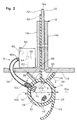
- a first embodiment of a safety edge system indicated generally at 8 employing a pneumatically operating sensing edge indicated generally at 10.
- a building wall 12 having a doorway 14 with a partially opened door 16.
- the pneumatic sensing edge 10 is positioned beneath the door 16 along its leading (i.e., bottom) edge surface 18.
- the door 15 is illustrated as an overhead door, it is within the scope and spirit of the invention to incorporate the system 8 with sensing edge 10, hereinafter described, along an edge of any door structure including a horizontally moving door (not shown) as desired.
- system 8 and sensing edge 10 are not limited to use in conjunction with doors, but might be used for other, like applications such as automatically moved windows, skylights, indoor partition walls, etc.
- the system 8 of the present invention is also particularly useful in explosive environments because the electrical components of the system can be located on an outer side of the door and shielded from a hazardous environment contained by the door.
- the system 8 and sensing edge 10 are intended for use with automatically closing doors or the like to protect persons, equipment and other objects, including the door itself, from injury or damage by causing the door to automatically stop or open in response to a force being applied to the sensing edge.
- Circuitry for stopping and/or reversing the movement of automatically closing doors and the like are generally known to those of ordinary skill. They comprise a relay or switch which causes an interrupt or reversal of the current to the door-closing device.
- the door 16 has, in addition to its leading edge surface 18, first and second major surfaces 20 and 22, which are on opposite sides of the door and vertical when the door 16 is in the closed position.
- the first preferred embodiment of the sensing edge 10 is installed along the lower, leading edge 18 of the door 16.
- the sensing edge 10 is formed by an elongated, one-piece, extrusion 28 of an air-impervious material.
- the extrusion 28 includes an elongated tubular member 30 of preferably circular cross sectional shape having an air impervious tubular wall 32.
- the extrusion 28 further includes a pair of laterally spaced apart support legs 36, 38 which extend the length of the extrusion.
- the support legs 36, 38 are asymmetrically located on the tubular member 30 so as to be spaced along an arc 40 of the tubular wall 32 having an angle A of less than 180°.
- the extrusion 28 further includes an elongated mounting strip 42 extending outwardly from the tubular wall 32 along the arc 40 between the pair of support legs 36, 38, and to a greater radial extent than either of the pair of support legs 36, 38.
- the extrusion 28 further includes an elongated weatherstrip 45 extending tangentially from the tubular wall 32 and preferably wrapping partially around the leading outer side of the tubular member 30 directly opposite the elongated mounting strip 42.
- the weatherstrip 45 hangs down to cover a small gap, which is desirably provided between the leading edge 18 of the door and the ground or floor within the doorway 14 when the door 16 is fully closed, to prevent damage to the door 16 or the door drive equipment (not depicted) by the door 16 striking the floor or ground.
- the support legs 36, 38, the mounting strip 42 and the weather strip 45 all extend the length of the tubular member 30.
- the support legs 36, 38 are asymmetrically located on the tubular member 30 so as to be spaced apart along an arc of the tubular wall extending over an angle "A" of less than 180 degrees, suggestedly less than 90 degrees and preferably only about 60 degrees.
- the support legs 36, 38 and the mounting strip 42 are all substantially planar.
- the planes of the support legs 36, 38 are symmetric with respect to the plane of the mounting strip 42 and each forms an angle "B" of about 60 degrees or less and preferably about 45 degrees with the plane of the mounting strip.
- closures 44 and 46 are provided in each of the two opposing open ends of the extruded tubular member 30 and are arranged to seal the opposing ends of the tubular member to air passage.
- each of the closures 44 and 46 is a conically shaped plug.
- the sensing edge 10 further includes a fluid coupling 50 which is preferably formed by a tubular, T-shaped connector 52 having opposing arms 52a, 52b and an intermediate transverse arm 52c.
- a length of tubing 54 preferably is mounted on one of the opposing arms 52b.
- the system 8 further includes a pneumatic or air pressure responsive switch 60, which is located outside of the sensing edge 10 and the tubular member 30.
- At least one tube 56 fluidly couples the hollow interior 34 of the tubular member sealed with the closures 44 and 46 and the air pressure responsive switch 60.
- One end of tube 56 is jammed over the end of the transverse arm 52c of connector 52 of the fluid coupling 50 exposed on the tubular member 30 while the remaining end of tube 56 is similarly fitted over an air pressure sensing port 60a provided on the switch.
- the exemplary door 16 depicted in the figures is a conventional steel door including a plurality of connected panels, a bottom one of which is indicated at 16a.
- first and second angle irons 16b and 16c are mounted on either of the major opposing surfaces of the panel 16a. These are held in place by conventional fasteners such as nuts and bolts (none depicted).
- the safety edge 10 is preferably first assembled by attaching or installing the fluid coupling S0 and closures 44 and 46 to the tubular member 30 of the extrusion, sealing its hollow interior 34 from air or other fluid passage except through the arm 52c of connector 52.
- One of the angles, for example, 16c is removed from the door 16.
- air pressure responsive switch 60 is mounted to the door 16 proximal to the sensing edge 10.
- Switch 60 might, for example, be mounted to the inner one 16c of the angles 16b, 16c, as depicted, for protection if door 16 is an exterior door.
- Tube 56 is mounted to arm 52c and port 60a, thereby fluidly coupling the hollow interior 34 of tubular member 30 of the sensing edge 10 with switch 60.
- Switch 60 is connected in a desired and conventional fashion with the door advancement circuitry (not depicted) to cause downward movement of the door 16 to at least stop or reverse direction when the tubular member 30 of the edge 10 is collapsed sufficiently to cause switch 60 to change states.
- each of the arms 52a, 52b and 52c of the T-shaped connector 52 is provided with barbs, serrations or other engagement structures which cause each arm in question to be releasably engaged with the tubular member 30 or tube 56 or length of tubing 54 to prevent the easy separation of each or any of those elements from the T-shaped connector.
- the pair of opposing arms 52a, 52b together have a maximum linear dimension along those arms which is greater than an inner diameter of the tubular member 30. This is to prevent the arms from being turned into the inner side of the tubular wall 32 in a way in which they are blocked by the tubular wall.
- the length of tubing 54 is provided as a further precaution to prevent the opposing arms 52a, 52b of the T-shaped connector 52 from being able to turn very far away from the center line of the tubular member 30.
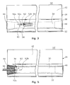
- Figs. 2-3 depict one possible mounting of connector 52.
- the arm 52c of the connector 52 can extend elsewhere through the tubular wall 32 of member 30, for example, in the arc 40 extending between the support legs 36 and 38, between one of those legs and the mounting strip 42, where the arm 52c is hidden and at least partially protected by the proximal leg 36 or 38.
- the lateral sides of the tubular member 30 bulge outwardly and form longitudinal channels 30a, 30b, which extend the length of the extrusion to the closures 44, 46 at the opposing ends of the member 30.
- the preferred solid closures 44, 46 tend to prevent full collapse of the ends of the tubular member 30 and provide transverse pneumatic channels extending at the ends of the member 30 between the longitudinal channels 30a, 30b .
- the tubular connector 52 is preferably located in one of the lateral sides of the elongated tubular member 30 or close to one of the closures 44, 46 so that the tubular member 30 does not fully collapse around it. In this way, the air pressure responsive switch 60 (see Fig. 2) remains fluidly coupled with the hollow interior of the tubular member 30.
- the sudden change in internal air pressure in the hollow interior of the tubular member 30 caused by its partial collapse is passed through connector 52 and tube 56 to the switch 60 causing that switch to reverse states and either halt the downward movement of the door 16 or reverse that movement to open the door 16.
- the barbed end 52a of connector 52 is received in and engages with the end of the tube 56, securing it in position in the central bore of the conical plug closure 44' at the one end of the edge 10'.
- the sensing edge 10' is identical to the original system 8 and sensing edge 10. Sensing edge lo' can be used on those installations where the fluid coupling tube 56 between the edge 10' and the air pressure responsive switch 60 can be extended around the longitudinal end of the leading edge 18 of the door 16.
- the extrusion 28 is formed from an air-impervious, preferably flexible and resilient material.
- the extrusion 30 suggestedly comprises and preferably consists essentially of neoprene.
- the closures 44, 44' and 46 are preferably simply commercially available plugs with or without central bore. These can be simply friction engaged with the extrusion 28 by being jammed into the end of the tubular member 30, or can be adhered into place, if desired, for greater security.
- the plugs can be neoprene but harder material plugs such as nylon or DelrinTM, a linear polyoxymethylene-type of acetal resin, can be used if necessary or desired.
- T-shaped connector 54 is preferably formed of a conventional plastic material harder than neoprene, for example, nylon, DelrinTM, or the like.
- the air pressure switch 60 can be any suitable pneumatic switch but is preferably an air wave type of pneumatic switch.
- Such switches typically include a diaphragm 62 carrying an electrical contact 64, a fixed contact 65 and an adjustable bleed valve 66, both of which are pneumatically coupled to the hollow interior of tubular member 30 and are indicated in phantom in Fig. 1.
- Such switches adjust automatically to slow variations in air pressure caused by atmospheric changes.
- Valve 66 also permits sudden overpressures to bleed off. They also can be adjusted to be much more sensitive to sudden air pressure changes than were other sealed air pressure responsive switches previously employed, which did not also have a self-adjusting capability.
- Air wave technology switches may be obtained from a variety of sources including, but not limited to
- an extrusion 28 having a tubular member 30 of circular cross-section permits the use of conventional, off the shelf conical plugs 44, 44', 46 as closures.
- the support legs 36 and 38 further stabilize the extrusion 30 on the door 16, preventing the tubular member 30 from rolling on the bottom of the door 16. As noted earlier, they further tend to pull the vertical sidewall portions of the tubular member back to a more generally vertical orientation when the tubular member 30 has been flattened horizontally, for example, by being compressed too much when the door 16 is closed farther than recommended. This is important because the tubular member 30 has its greatest internal volume and therefore is potentially most sensitive when it is circular in cross section. Without the legs 36, 38, the sidewalls of the tubular member 30 would tend to take a folded set and remain folded for a longer period of time if compressed too much during normal door closure.
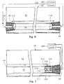
- extrusion 28 has been described being used with a pneumatic switch 60 in sensing edge systems 10, 10', it is equally suited for use with other types of switches.
- Fig. 6 shows extrusion 28 in another sensing edge system 110 employing a light source 112 in the central bore of one conical plug closure 44' in one end of tubular member 30 and a light responsive photocell 114 in the central bore of another conical plug closure 46' in the opposing end of tubular member 30.
- Light source 112 and photocell 114 together effectively form an optical switch.
- Photocell 114 is part of a control circuit 160, which is responsive to a loss of light sensed by photocell 114 and caused by collapse of the tubular member 30 between source 112 and photocell 114, to switch off or reverse a prime mover driving the door or other movable structure mounting the extrusion 28.
- Light 112 can be powered from circuit 160 as indicated or an independent source.
- Extrusion 28 can also be used with mechanical, momentary contact type switches, which are installed in the hollow interior of tubular member 30.
- Fig. 7 shows extrusion 28 in yet another sensing edge system 210 employing a first and second electrical conductors 212 and 214, respectively, separated from one another by thin, transversely extending, soft foam rubber spacers 216, which may be cross-members of a ladder-like foam member 218. Additional foam members 220, 222 may be provided on the outer sides of conductors 212, 214, respectively to maintain their positions within tubular member 30.
- the planes of the contacts 212, 214 should be perpendicular to the plane of the mounting strip 42.
- Conductors 212, 214 form contacts of a momentary switch that closes when conductors 212, 214 touch each other.
- the switch forms part of a control circuit 260, which also can be used to switch off or reverses the motion of a prime mover. Any of a variety of existing contacts and holders used in other safety edges might be used in tubular member 30 of extrusion 28.
Landscapes
- Physics & Mathematics (AREA)
- Fluid Mechanics (AREA)
- Power-Operated Mechanisms For Wings (AREA)
- Geophysics And Detection Of Objects (AREA)
- Window Of Vehicle (AREA)
- Switches Operated By Changes In Physical Conditions (AREA)
Applications Claiming Priority (4)
| Application Number | Priority Date | Filing Date | Title |
|---|---|---|---|
| US63752396A | 1996-04-25 | 1996-04-25 | |
| US637523 | 1996-04-25 | ||
| US754769 | 1996-11-20 | ||
| US08/754,769 US5728984A (en) | 1996-11-20 | 1996-11-20 | Sensing safety edge systems |
Publications (2)
| Publication Number | Publication Date |
|---|---|
| EP0803629A2 true EP0803629A2 (de) | 1997-10-29 |
| EP0803629A3 EP0803629A3 (de) | 1998-03-18 |
Family
ID=27092862
Family Applications (1)
| Application Number | Title | Priority Date | Filing Date |
|---|---|---|---|
| EP97106858A Withdrawn EP0803629A3 (de) | 1996-04-25 | 1997-04-25 | Sicherheitsfühlleistensystem |
Country Status (1)
| Country | Link |
|---|---|
| EP (1) | EP0803629A3 (de) |
Cited By (2)
| Publication number | Priority date | Publication date | Assignee | Title |
|---|---|---|---|---|
| EP1496184A3 (de) * | 2003-07-10 | 2007-03-14 | Gummi-Welz GmbH & Co. KG | Fussschutzleiste |
| EP1231348A3 (de) * | 2001-02-08 | 2009-04-15 | Marantec Antriebs- und Steuerungstechnik GmbH & Co. KG. | Sicherheitsvorrichtung zum Anhalten motorisch bewegter Gegenstände |
Family Cites Families (5)
| Publication number | Priority date | Publication date | Assignee | Title |
|---|---|---|---|---|
| US2952751A (en) * | 1958-02-03 | 1960-09-13 | Cookson Company | Astragal with pressure switch |
| US4896714A (en) * | 1987-03-24 | 1990-01-30 | Hy-Roll Manufacturing, Inc. | Roll door |
| FR2663363A1 (fr) * | 1990-06-15 | 1991-12-20 | Roussel Gerard | Dispositif de securite pour porte a fonctionnement automatique. |
| AT400470B (de) * | 1993-10-25 | 1996-01-25 | Mewald Gmbh | Schaltleiste |
| DE9418117U1 (de) * | 1993-12-21 | 1995-02-02 | Huber & Suhner AG, Pfäffikon | Schutzeinrichtung für die Schließkanten von kraftbetätigten Vorrichtungen |
-
1997
- 1997-04-25 EP EP97106858A patent/EP0803629A3/de not_active Withdrawn
Cited By (2)
| Publication number | Priority date | Publication date | Assignee | Title |
|---|---|---|---|---|
| EP1231348A3 (de) * | 2001-02-08 | 2009-04-15 | Marantec Antriebs- und Steuerungstechnik GmbH & Co. KG. | Sicherheitsvorrichtung zum Anhalten motorisch bewegter Gegenstände |
| EP1496184A3 (de) * | 2003-07-10 | 2007-03-14 | Gummi-Welz GmbH & Co. KG | Fussschutzleiste |
Also Published As
| Publication number | Publication date |
|---|---|
| EP0803629A3 (de) | 1998-03-18 |
Similar Documents
| Publication | Publication Date | Title |
|---|---|---|
| US5728984A (en) | Sensing safety edge systems | |
| US5438798A (en) | Safety edge assembly for a movable closure | |
| US4944116A (en) | Sensor strip | |
| US5832665A (en) | Sensing edge | |
| US5296658A (en) | Safety edge switch for detection of obstructions encountered by a moving object | |
| CA1048066A (en) | Pressure sensitive door edge construction | |
| US6041844A (en) | Overhead door and track therefor | |
| US4234875A (en) | Security structure | |
| US5934019A (en) | Mounting bracket for safety device employing beam path | |
| US4706001A (en) | Industrial robot | |
| US4074112A (en) | Switch assembly having movable contact face configuration for penetrating frost or ice layer on adjacent contact surface | |
| US4972054A (en) | Redundant sensing edge for a door | |
| US9109365B2 (en) | Insulated cover for attic openings | |
| US5566504A (en) | Combination door gasket and safety edge strip | |
| US4770224A (en) | Power operated industrial door | |
| US5839227A (en) | Safety edge for an electrically operated door | |
| US4317970A (en) | Entrapment prevention device | |
| CA2456710C (en) | Dual safety-edge for an overhead door | |
| EP0803629A2 (de) | Sicherheitsfühlleistensystem | |
| JPH04500548A (ja) | 戸板端部の閉鎖安全装置 | |
| WO2001033022A3 (en) | Window protection apparatus | |
| US5912625A (en) | Wave sensor control system | |
| WO1999032749A3 (en) | Reinforced burglar- and storm-resistant cover for windows and doors | |
| ES2110928T1 (es) | Accionador de freno de resorte con proteccion contra el polvo. | |
| KR950704093A (ko) | 로봇 장치(Robot Apparatus) |
Legal Events
| Date | Code | Title | Description |
|---|---|---|---|
| PUAI | Public reference made under article 153(3) epc to a published international application that has entered the european phase |
Free format text: ORIGINAL CODE: 0009012 |
|
| AK | Designated contracting states |
Kind code of ref document: A2 Designated state(s): DE ES FR GB IT |
|
| PUAL | Search report despatched |
Free format text: ORIGINAL CODE: 0009013 |
|
| AK | Designated contracting states |
Kind code of ref document: A3 Designated state(s): DE ES FR GB IT |
|
| STAA | Information on the status of an ep patent application or granted ep patent |
Free format text: STATUS: THE APPLICATION IS DEEMED TO BE WITHDRAWN |
|
| 18D | Application deemed to be withdrawn |
Effective date: 19980919 |