EP0803465B1 - Equipment for detecting the instantaneous load and/or the long duration stress state of handling means, in particular of lifting devices - Google Patents
Equipment for detecting the instantaneous load and/or the long duration stress state of handling means, in particular of lifting devices Download PDFInfo
- Publication number
- EP0803465B1 EP0803465B1 EP97250125A EP97250125A EP0803465B1 EP 0803465 B1 EP0803465 B1 EP 0803465B1 EP 97250125 A EP97250125 A EP 97250125A EP 97250125 A EP97250125 A EP 97250125A EP 0803465 B1 EP0803465 B1 EP 0803465B1
- Authority
- EP
- European Patent Office
- Prior art keywords
- load
- motor
- current
- phase
- induction motor
- Prior art date
- Legal status (The legal status is an assumption and is not a legal conclusion. Google has not performed a legal analysis and makes no representation as to the accuracy of the status listed.)
- Expired - Lifetime
Links
Images
Classifications
-
- G—PHYSICS
- G07—CHECKING-DEVICES
- G07C—TIME OR ATTENDANCE REGISTERS; REGISTERING OR INDICATING THE WORKING OF MACHINES; GENERATING RANDOM NUMBERS; VOTING OR LOTTERY APPARATUS; ARRANGEMENTS, SYSTEMS OR APPARATUS FOR CHECKING NOT PROVIDED FOR ELSEWHERE
- G07C3/00—Registering or indicating the condition or the working of machines or other apparatus, other than vehicles
-
- B—PERFORMING OPERATIONS; TRANSPORTING
- B66—HOISTING; LIFTING; HAULING
- B66C—CRANES; LOAD-ENGAGING ELEMENTS OR DEVICES FOR CRANES, CAPSTANS, WINCHES, OR TACKLES
- B66C13/00—Other constructional features or details
- B66C13/16—Applications of indicating, registering, or weighing devices
-
- B—PERFORMING OPERATIONS; TRANSPORTING
- B66—HOISTING; LIFTING; HAULING
- B66D—CAPSTANS; WINCHES; TACKLES, e.g. PULLEY BLOCKS; HOISTS
- B66D1/00—Rope, cable, or chain winding mechanisms; Capstans
- B66D1/54—Safety gear
-
- H—ELECTRICITY
- H02—GENERATION; CONVERSION OR DISTRIBUTION OF ELECTRIC POWER
- H02P—CONTROL OR REGULATION OF ELECTRIC MOTORS, ELECTRIC GENERATORS OR DYNAMO-ELECTRIC CONVERTERS; CONTROLLING TRANSFORMERS, REACTORS OR CHOKE COILS
- H02P29/00—Arrangements for regulating or controlling electric motors, appropriate for both AC and DC motors
- H02P29/40—Regulating or controlling the amount of current drawn or delivered by the motor for controlling the mechanical load
Definitions
- the invention relates to a device for detecting the instantaneous load and / or the permanent loading of conveyors, in particular hoists, comprising a load measuring device and an electric motor as a drive means for the Lifting and lowering a load.
- Load measuring devices for hoists are known.
- a load measuring device for a hoist with a Hubwerksmotor described which is arranged in the support means and by means of a Switzerlandmeßstabes allows the detection of the load.
- the Switzerlandmeßstab has a Strain gauge, whose electrical resistance varies depending on the load acting on the hoist load changes, so that by detecting the Resistance of the strain gauge or a voltage drop at the Strain gauge at constant current flow proportional to the load electrical signal is generated. It allows a special bridge circuit of strain gauges and resistors a very accurate determination of the Load.
- the burden of Constantly checking the hoist and protecting the hoist from overloading by connected to the load measuring electronic Wam pleaseden which automatically switch off the hoist when the rated load is exceeded.
- DE 40 38 981 A1 discloses a hoist drive with an asynchronous motor, one feeding the motor with AC variable frequency Frequency converter and one of the frequency of the frequency converter to one in particular infinitely selectable frequency setpoint setting Control circuitry.
- the control circuit comprises a detection device which a measure of the instantaneous torque of the engine Determined load value, as well as a data store, the data for a Limit characteristic stores the relationship between the maximum permissible values Frequencies of alternating current on the one hand and load values for one on the other hand represents predetermined power of the engine.
- the control circuit sets the frequency of the frequency converter to one dependent on the frequency determining load value according to the data stored in the data memory Data resulting frequency value and leads to a change in the Load value after.
- Load measuring devices also serve to detect Load characteristics of hoists, by equivalent damages Load values based on the measured loads taking into account the Charging time determined and summed up. So is from the DE-GM 2 ° 95 03 416 U1 a device for determining the dynamic load of Components, systems and machines are known in the monitoring of the System load load values over several load changes formed and accumulated in a memory are stored. Exceeding the accumulated total load value is triggered by triggering a corresponding Alarm signal displayed; In this way it is possible a regeneration and / or an exchange of the hoist, for example, according to the relevant neither too early nor too late, and thus the Optimum use of hoist with regard to service life.
- the disadvantage here is the relatively large effort required to capture the total load and for monitoring a predetermined lifetime limit is required.
- the object of the invention is therefore to provide a device for detecting the current load and / or the duration of use of subsidies for Hoists create no changes or fixtures in load-bearing parts a hoist or structure require and still a very accurate measurement enable. In addition, it should allow this detection device, the accumulated permanent load on the hoist with sufficient accuracy technically very simple way to determine.
- the invention provides that the electric motor as a three-phase asynchronous motor is formed by the load measuring the active power of the Three-phase asynchronous motor can be detected by means of a current and voltage measurement and is comparable to a reference power to determine the current Load, the reference power being a calculated power of Drehstromasynchronmotors for driving a nominal load capacity of the conveyor is.
- the solution according to the invention makes it possible, without changes or installations in carrying parts of the conveyor the current load as well Continuous stress with high accuracy, especially in the field of Nominal load to be determined. So it is possible, for example, over the Active power consumption of the three-phase asynchronous motor load, in particular if this is in the range of the rated load, with a measuring error of 1 to 2% determine.
- the detection device as load control for protection the conveyor ensures the solution of the invention a perfect Detection of overload.
- the detection of the continuous load of the conveyor is with the Solution according to the invention also possible with little effort.
- the something greater measurement error in the partial load range is for the detection of continuous load over a long period of subordinate importance, especially as in the case of Continuous stress the ratio of partial load to rated load with the third Potency enters into the continuous load of the subsidy, according to the relevant provisions for determining the lifetime limit of Funding.
- the device according to the invention consequently ensures the required high accuracy, which is sufficient for a sufficiently accurate determination of Continuous loading of the conveyor is necessary.
- the current load as the ratio or difference is formed from the active power and the reference power and that a Display device for displaying the current load as load control is provided.
- a shutdown device is provided to interrupt the lifting movement by switching off the motor when the current load exceeds a predetermined load, this being must be within the permissible load values.
- the accuracy of the detection of the current heat losses can be improved if the temperature of the stator winding measurable and the electrical resistance of the Stator winding from whose cold resistance is calculated.
- the accuracy of the detection of the permanent load and / or the current Load is further improved by the measured active power consumption to the idling losses of the conveyor (so by a corresponding offset) is diminished, since these too do not contribute to the lifting of the subsidy; the idling losses can be measured by measuring the power consumption of the conveyor be determined without load.
- the switching of the direction of rotation of the Drehstromasynchronmotors in that a reversing switch for turning the Motor phase leads is provided.
- the current measurement for determining the active power consumption of the Drehstromasynchronmotors takes place in that a current transformer is provided, the the current in one of the turned for a change of direction Motor phase lead detected.
- This has the advantage that the differing Phase sequences between the measured current and the measured voltage "Lifting the load” and when “lowering the load” are distinguishable, so that the detection the permanent load and / or the current load on the basis of Active power consumption only in the relevant state "lifting the load” takes place.
- the invention proposes that the voltage measurement between the Motor phase lead whose current is detected, and one of the other two Motor phase leads takes place.
- the advantage of this measurement is that Voltage and current can only be measured simultaneously if the State "lifting the load" is switched on.
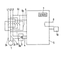
- An embodiment of the invention is schematically in the single figure illustrated, the means for detecting the current load and / or the continuous stress of a hoist with a three-phase asynchronous as Drive means shows.
- a device for detecting the permanent load and / or the current load of a three-phase asynchronous motor 1 as a drive means of a Hubtechnik shown.
- the three-phase asynchronous motor 1 is as a squirrel-cage rotor formed and via motor phase leads 2a, 2b, 2c to three-phase network phases L1, L2, L3 connected to a three-phase system.
- the motor phase feeder 2c is over a current transformer 3, through which the stator current of the asynchronous motor. 1 is measurable.
- the current transformer 3 generates a stator current proportional Tension; via lines 4, the output of the current transformer 3 with a Evaluation unit 5 connected.
- the motor phase leads 2a, 2b, 2c Connected via leads 6a, 6b, 6c to the evaluation unit 5.
- the determination of the active power consumption of the Drehstromasynchronmotors 1 based on the measured in the evaluation unit 5 Voltage and current values of the three-phase asynchronous motor 1 in per se known Way, but controlled by the evaluation unit 5 only in the state "lifting the load ", since only in this condition a clear connection between the Active power consumption and a calculable reference power of the hoist exist.
- the determined active power consumption is in the evaluation unit 5 by an offset reduced, which takes into account the idling losses of the hoist, which in essentially from magnetic reversal losses of the magnetic sheets and the Friction losses of the motor rotor of the three-phase asynchronous motor. 1 composed.
- the value of these losses is by means of a power measurement of the idle-driven three-phase asynchronous motor 1 can be easily determined or calculable on the basis of the design data and in the evaluation unit 5 in one Storage element filed.
- the active power consumption is in each case by the proportion of the current heat losses the motor stator winding corrected, the current heat losses from the measured current and the electrical resistance of the stator winding of Three-phase asynchronous motor 1 are calculated.
- electrical resistance value of Stator winding As electrical resistance value of Stator winding is used their cold resistance, which from the winding data of the three-phase asynchronous motor 1 is calculated.
- the temperature dependence of the electrical resistance of the Stator winding by detecting the winding temperature to take into account by for cold resistance a corresponding correction value (positive or negative) added becomes.
- the electrical resistance of the stator winding is also in one Memory element of the evaluation unit 5 stored.
- the evaluation unit 5 determines the instantaneous load of the hoist based on the reference power and displays the difference or the ratio of measured active power consumption and reference power;
- the reference power is therefore calculated solely from the design data of the hoist.
- the reference power is the proportion of power that the three-phase asynchronous motor. 1 removed from the three-phase network and transmits over the motor gap to the moment to generate the three-phase asynchronous motor 1 for lifting the rated load at Constant stroke speed transmits over the drive shaft.
- the reference power is calculated from the field power of the Three-phase asynchronous motor 1 at rated load and results from the rotational frequency, with the magnetic field of the stator in the air gap between the stator and rotor of the Drehstromasynchronmotors 1 rotates, and the output torque. Due to the magnetic transmission through the air gap are the field power and the delivered moment directly proportional, i. the reference performance is a measure of the Load - dependent part of the power required for lifting the rated load over the Air gap of the engine must be transferred to the rotor.
- the Load of the hoist by a momentary load clearly by comparison the stator side measured active power consumption of Three-phase asynchronous motor 1 (of the stator) with the calculated reference power be determined.
- the difference or ratio of these two benefits equal to the difference or the ratio between the momentary load and the rated load, is indicated by an in the evaluation unit 5 integrated display device 10 as a current load displayable, which serves an operator as a load control.
- a current load displayable which serves an operator as a load control.
- Control line 8 is provided, which is connected to a switch (schematically in the Figur), via which the power supply of the three-phase asynchronous motor. 1 is interrupted when the current load the predetermined allowable Exceeding load.
- the control line 8 can only be activated when the Hoist is in the "lifting the load" state.
- the line 6c is for Evaluation unit 5 is provided, which ensures that the voltage measurement between the motor phase supply line 2c, whose current is detected, and the other two Motor phase leads 2a, 2b can be measured.
- the voltage measurement takes place the non-turned motor phase feeder 2a before the reversing switch 9 and the reversible motor phase lead 2c or 2b behind the reversing switch 9 related to the potential of the motor phase feeder 2a.
- Both states are characterized in the Evaluation unit 5 distinguishable, so that only when lifting the load current and Measured voltage and from this the relevant for the current load, the Reference power corresponding active power consumption of Three-phase asynchronous motor 1 is determined.
- the Evaluation unit 5 can correctly determine due to the selected wiring, whether the hoist is in the "lifting the load” or “lowering the load” position, and thus for the detection of the current load and / or the Permanent load determine the relevant active power.
- the cheapest Detection time is the one where the load capacity with constant lifting speed is lifted; The detection therefore always takes place in the embodiment with a short time delay, so after completion of the startup, so after the start-up phase.
- the current load as instantaneous stress the conveyor over time integrable and in a designated storage unit can be stored; the accumulated permanent load, that is the one in the storage unit stored integral value can be displayed by the load indicator 7.
- the load indicator 7 it is also possible in determining continuous stress the Ratio of partial load to nominal load with the third power in the Continuous load of the conveyor to be incorporated.
- the connections for the voltage measurement are used at the same time Power supply of the evaluation unit 5.
Landscapes
- Engineering & Computer Science (AREA)
- Mechanical Engineering (AREA)
- Power Engineering (AREA)
- Physics & Mathematics (AREA)
- General Physics & Mathematics (AREA)
- Control Of Electric Motors In General (AREA)
- Control Of Ac Motors In General (AREA)
- Control And Safety Of Cranes (AREA)
- Tests Of Circuit Breakers, Generators, And Electric Motors (AREA)
- Force Measurement Appropriate To Specific Purposes (AREA)
Description
Die Erfindung betrifft eine Einrichtung zur Erfassung der momentanen Belastung und/oder der Dauerbeanspruchung von Fördermitteln, insbesondere von Hubwerken, die eine Lastmeßeinrichtung umfaßt und einen Elektromotor als Antriebsmittel für das Heben und Senken einer Traglast aufweist.The invention relates to a device for detecting the instantaneous load and / or the permanent loading of conveyors, in particular hoists, comprising a load measuring device and an electric motor as a drive means for the Lifting and lowering a load.
Lastmeßeinrichtungen für Hebezeuge sind bekannt. So ist beispielsweise in der DE 28 23 401 A1 eine Lastmeßeinrichtung für ein Hebezeug mit einem Hubwerksmotor beschrieben, die im Tragmittel angeordnet ist und mittels eines Zugmeßstabes die Erfassung der Traglast ermöglicht. Der Zugmeßstab weist einen Dehnungsmeßstreifen auf, dessen elektrischer Widerstand sich in Abhängigkeit von der am Hubwerk angreifenden Traglast ändert, so daß durch Erfassung des Widerstands des Dehnungsmeßstreifens oder eines Spannungsabfalls am Dehnungsmeßstreifen bei konstantem Stromfluß ein zur Traglast proportionales elektrisches Signal erzeugt wird. Dabei ermöglicht eine spezielle Brückenschaltung von Dehnungsmeßstreifen und Widerständen eine sehr genaue Bestimmung der Traglast. Somit ist es mit einer solchen Lastmeßeinrichtung möglich, die Belastung des Hubwerks ständig zu kontrollieren und das Hubwerk vor Überlastung zu schützen, indem an die Lastmeßeinrichtung elektronische Wameinrichtungen angeschlossen werden, die bei Überschreiten der Nenntraglast das Hubwerk selbsttätig abschalten.Load measuring devices for hoists are known. For example, in the DE 28 23 401 A1 a load measuring device for a hoist with a Hubwerksmotor described, which is arranged in the support means and by means of a Zugmeßstabes allows the detection of the load. The Zugmeßstab has a Strain gauge, whose electrical resistance varies depending on the load acting on the hoist load changes, so that by detecting the Resistance of the strain gauge or a voltage drop at the Strain gauge at constant current flow proportional to the load electrical signal is generated. It allows a special bridge circuit of strain gauges and resistors a very accurate determination of the Load. Thus, it is possible with such a load measuring device, the burden of Constantly checking the hoist and protecting the hoist from overloading by connected to the load measuring electronic Wameinrichtungen which automatically switch off the hoist when the rated load is exceeded.
Die DE 40 38 981 A1 offenbart einen Hubwerksantrieb mit einem Asynchronmotor, einem den Motor mit Wechselstrom änderbarer Frequenz speisenden Frequenzumrichter und einer die Frequenz des Frequenzumrichters auf einen insbesondere stufenlos wählbaren Frequenz-Sollwert einstellenden Steuerschaltung. Die Steuerschaltung umfasst eine Ermittlungseinrichtung, die einen ein Maß für das momentane Drehmoment des Motors repräsentierenden Belastungswert ermittelt, sowie einen Datenspeicher, der Daten für eine Grenzkennlinie speichert, die den Zusammenhang zwischen maximal zulässigen Frequenzen des Wechselstromes einerseits und Belastungswerte für eine vorgegebene Leistung des Motors andererseits repräsentiert. Die Steuerschaltung stellt die Frequenz des Frequenzumrichters auf einen abhängig von dem ermittelnden Belastungswert entsprechend den im Datenspeicher gespeicherten Daten sich ergebenden Frequenzwert ein und führt diesen bei einer Änderung des Belastungswertes nach.DE 40 38 981 A1 discloses a hoist drive with an asynchronous motor, one feeding the motor with AC variable frequency Frequency converter and one of the frequency of the frequency converter to one in particular infinitely selectable frequency setpoint setting Control circuitry. The control circuit comprises a detection device which a measure of the instantaneous torque of the engine Determined load value, as well as a data store, the data for a Limit characteristic stores the relationship between the maximum permissible values Frequencies of alternating current on the one hand and load values for one on the other hand represents predetermined power of the engine. The control circuit sets the frequency of the frequency converter to one dependent on the frequency determining load value according to the data stored in the data memory Data resulting frequency value and leads to a change in the Load value after.
Nachteilig ist bei dieser Lastmeßeinrichtung, daß die Anordnung der Meßelemente in den tragenden Teilen des Hubwerks oder Krans u. dgl. erfolgt, was aufwendig ist und spezielle Anpassungen im konstruktiven Aufbau insbesondere der tragenden Teile erfordert. Die Nachrüstung bereits in Betrieb befindlicher Hubwerke ist aufgrund der erforderlichen Umbaumaßnahmen relativ teuer und aufwendig.A disadvantage of this load measuring that the arrangement of the measuring elements in the load-bearing parts of the hoist or crane u. Like. Is done, which is expensive and special adjustments in the structural design, in particular of the load-bearing parts requires. The retrofitting of hoists already in operation is due to the required conversion measures relatively expensive and expensive.
Lastmeßeinrichtungen dienen darüber hinaus zur Erfassung von Belastungskennwerten von Hubwerken, indem schädigungsäquivalente Belastungswerte anhand der gemessenen Traglasten unter Berücksichtigung der Belastungszeit ermittelt und aufsummiert werden. So ist aus der DE-GM 2°95 03 416 U1 ein Gerät zur Ermittlung der dynamischen Beanspruchung von Bauteilen, Anlagen und Maschinen bekannt, bei der zur Überwachung der Anlagenbeanspruchung Belastungswerte über mehrere Lastwechsel gebildet und aufsummiert in einem Speicher abgelegt werden. Die Überschreitung des aufsummierten Gesamtbelastungswertes wird durch Auslösung eines entsprechenden Alarmsignals angezeigt; auf diese Weise ist es möglich, eine Regenerierung und/oder einen Austausch des Hubwerks beispielsweise entsprechend den einschlägigen gesetzlichen Vorschriften weder zu früh noch zu spät durchzuführen und damit das Hubwerk hinsichtlich der Lebensdauer optimal zu nutzen. Nachteilig ist auch hier der relativ große Aufwand, der zur Erfassung der Gesamtbelastung und zur Überwachung eines vorgegebenen Lebensdauergrenzwertes erforderlich ist.Load measuring devices also serve to detect Load characteristics of hoists, by equivalent damages Load values based on the measured loads taking into account the Charging time determined and summed up. So is from the DE-GM 2 ° 95 03 416 U1 a device for determining the dynamic load of Components, systems and machines are known in the monitoring of the System load load values over several load changes formed and accumulated in a memory are stored. Exceeding the accumulated total load value is triggered by triggering a corresponding Alarm signal displayed; In this way it is possible a regeneration and / or an exchange of the hoist, for example, according to the relevant neither too early nor too late, and thus the Optimum use of hoist with regard to service life. The disadvantage here is the relatively large effort required to capture the total load and for monitoring a predetermined lifetime limit is required.
Die einfachste Methode, die aufsummierten Belastungswerte eines Hubwerks zu ermitteln, besteht bekanntermaßen darin, einen Betriebsstundenzähler beispielsweise in die Netzzuleitung des Hubmotors einzuschalten. Diese sehr einfache Methode hat allerdings einen entscheidenden Nachteil: Die Dauerbeanspruchung des Hubwerks wird nur sehr grob ermittelt; die große Ungenauigkeit bei einer derartigen Erfassung der Gesamtbelastung muß durch entsprechend groß gewählte Sicherheitsfaktoren berücksichtigt werden. Wird das Hubwerk relativ häufig im unteren Teillastbereich betrieben, erfolgt eine Regenerierung oder ein Auswechseln des Hubwerks regelmäßig zu früh, d.h. die an sich mögliche Lebensdauer des Hubwerks kann unter Berücksichtigung der einschlägigen Vorschriften aus Sicherheitsgründen nicht voll genutzt werden, was regelmäßig mit beträchtlichen Kosten verbunden ist.The easiest way to add the summed load values of a hoist determine, is known to be an hour meter, for example to turn into the mains supply of the hoist motor. This very simple method has however, one decisive disadvantage: the continuous load of the hoist is determined only very roughly; the great inaccuracy of such detection The total load must be determined by appropriately large safety factors be taken into account. If the hoist is relatively common in the lower part load range operated, there is a regeneration or replacement of the hoist regularly too early, i. the per se possible life of the hoist can under For safety reasons, the relevant provisions are not fully be used, which is regularly associated with considerable costs.
Die Aufgabe der Erfindung ist es daher, eine Einrichtung zur Erfassung der momentanen Belastung und/oder der Dauerbeanspruchung von Fördermitteln für Hubwerke zu schaffen, die keine Veränderungen oder Einbauten in tragende Teile eines Hubwerkes oder Tragwerkes erfordern und trotzdem eine sehr genaue Messung ermöglichen. Außerdem soll es diese Erfassungseinrichtung ermöglichen, die aufsummierte Dauerbeanspruchung des Hubwerks mit ausreichender Genauigkeit auf technisch sehr einfache Art und Weise zu bestimmen.The object of the invention is therefore to provide a device for detecting the current load and / or the duration of use of subsidies for Hoists create no changes or fixtures in load-bearing parts a hoist or structure require and still a very accurate measurement enable. In addition, it should allow this detection device, the accumulated permanent load on the hoist with sufficient accuracy technically very simple way to determine.
Die Lösung dieser Aufgabe ist erfindungsgemäß gekennzeichnet durch die im Patentanspruch 1 angegebenen Merkmale. Durch die kennzeichnenden Merkmale der Unteransprüche 2 bis 13 ist die Einrichtung in vorteilhafter Weise weiter ausgestaltet.The solution to this problem is inventively characterized by in the Claim specified features. Due to the distinguishing features of Dependent claims 2 to 13, the device is further configured in an advantageous manner.
Die Erfindung sieht vor, daß der Elektromotor als Drehstromasynchronmotor ausgebildet ist, durch die Lastmeßeinrichtung die Wirkleistungsaufnahme des Drehstromasynchronmotors anhand einer Strom- und Spannungsmessung erfaßbar und mit einer Bezugsleistung vergleichbar ist zur Ermittlung der momentanen Belastung, wobei die Bezugsleistung eine rechnerisch bestimmte Leistung des Drehstromasynchronmotors für das Treiben einer Nenntraglast des Fördermittels ist.The invention provides that the electric motor as a three-phase asynchronous motor is formed by the load measuring the active power of the Three-phase asynchronous motor can be detected by means of a current and voltage measurement and is comparable to a reference power to determine the current Load, the reference power being a calculated power of Drehstromasynchronmotors for driving a nominal load capacity of the conveyor is.
Die erfindungsgemäße Lösung ermöglicht es, ohne Veränderungen oder Einbauten in tragende Teile des Fördermittels die momentane Belastung als auch die Dauerbeanspruchung mit hoher Genauigkeit insbesondere im Bereich der Nenntraglast zu bestimmen. So ist es beispielsweise möglich, über die Wirkleistungsaufnahme des Drehstromasynchronmotors die Belastung, insbesondere wenn diese im Bereich der Nenntraglast liegt, mit einem Meßfehler von 1 bis 2 % zu bestimmen. Bei Einsatz der Erfassungseinrichtung als Belastungskontrolle zum Schutz des Fördermittels gewährleistet die erfindungsgemäße Lösung ein einwandfreies Erkennen von Überlast.The solution according to the invention makes it possible, without changes or installations in carrying parts of the conveyor the current load as well Continuous stress with high accuracy, especially in the field of Nominal load to be determined. So it is possible, for example, over the Active power consumption of the three-phase asynchronous motor load, in particular if this is in the range of the rated load, with a measuring error of 1 to 2% determine. When using the detection device as load control for protection the conveyor ensures the solution of the invention a perfect Detection of overload.
Die Erfassung der Dauerbeanspruchung des Fördermittels ist mit der erfindungsgemäßen Lösung ebenfalls mit geringem Aufwand möglich. Der etwas größere Meßfehler im Teillastbereich ist für die Erfassung der Dauerbeanspruchung über einen langen Zeitraum von untergeordneter Bedeutung, insbesondere da bei der Dauerbeanspruchung das Verhältnis von Teiltraglast zu Nenntraglast mit der dritten Potenz in die Dauerbeanspruchung des Fördermittels eingeht, entsprechend den einschlägigen Vorschriften zur Bestimmung des Lebensdauergrenzwertes von Fördermitteln. Die erfindungsgemäße Einrichtung gewährleistet folglich die erforderliche hohe Meßgenauigkeit, die für eine hinreichend genaue Bestimmung der Dauerbeanspruchung des Fördermittels notwendig ist.The detection of the continuous load of the conveyor is with the Solution according to the invention also possible with little effort. The something greater measurement error in the partial load range is for the detection of continuous load over a long period of subordinate importance, especially as in the case of Continuous stress the ratio of partial load to rated load with the third Potency enters into the continuous load of the subsidy, according to the relevant provisions for determining the lifetime limit of Funding. The device according to the invention consequently ensures the required high accuracy, which is sufficient for a sufficiently accurate determination of Continuous loading of the conveyor is necessary.
Zur einfachen Kontrolle der momentanen Belastung durch eine Bedienperson wird vorgeschlagen, daß die momentane Belastung als das Verhältnis oder der Differenz aus der Wirkleistungsaufnahme und der Bezugsleistung gebildet ist und daß eine Anzeigeeinrichtung zur Anzeige der momentanen Belastung als Belastungskontrolle vorgesehen ist.For easy control of the current load by an operator suggested that the current load as the ratio or difference is formed from the active power and the reference power and that a Display device for displaying the current load as load control is provided.
Zum selbsttätigen Schutz des Fördermittels ist eine Abschalteinrichtung vorgesehen zur Unterbrechung der Hubbewegung durch Abschalten des Motors, wenn die momentane Belastung eine vorgegebene Belastung überschreitet, wobei diese innerhalb der zulässigen Belastungswerte liegen muß.For automatic protection of the conveyor a shutdown device is provided to interrupt the lifting movement by switching off the motor when the current load exceeds a predetermined load, this being must be within the permissible load values.
Zur Erfassung der Dauerbeanspruchung des Fördermittels wird vorgeschlagen, daß die momentane Belastung als momentane Beanspruchung des Fördermittels über der Zeit integrierbar und in einer vorgesehenen Speichereinheit ablegbar und mittels einer Belastungsanzeigeeinrichtung anzeigbar ist. Auf diese Weise ist es mit einfachen Mitteln möglich, die wirkliche Dauerbeanspruchung des Fördermittels korrekt zu erfassen.To detect the permanent load of the conveyor is proposed that the momentary load as instantaneous load of the conveyor over the Time integrable and stored in a designated storage unit and by means of a Load indicator is displayed. This way it is simple Means possible, the actual duration stress of the conveyor to correctly to capture.
Zweckmäßigerweise ist die Bezugsleistung B für das vertikale Heben aus dem
Antriebsmoment des Drehstromasynchronmotors für die Nenntraglast und der
synchronen Drehfrequenz durch folgende Formel bestimmt:
m = Traglast
g = Erdbeschleunigung
RTR = Trommelradius
f = Netzfrequenz
i = Getriebeübersetzung
z = Einscherung
p = Polpaarzahl des Asynchronmotors
η = Getriebwirkungsgrad
bedeuten.Advantageously, the reference power B for vertical lifting from the drive torque of the three-phase asynchronous motor for the rated load and the synchronous rotational frequency is determined by the following formula:
m = load
g = gravitational acceleration
R TR = drum radius
f = mains frequency
i = gear ratio
z = reeving
p = pole pair number of the asynchronous motor
η = transmission efficiency
mean.
Es hat sich als vorteilhaft herausgestellt, als Bezugsleistung des Fördermittels eine aus den konstruktiven Parametem des Fördermittels berechnete Leistungsgröße zu verwenden, so daß aufwendige und häufig zu wiederholende Eichmessungen entfallen können.It has proved to be advantageous as a reference performance of the conveyor a The capacity calculated from the design parameters of the conveyor use, so that consuming and often repeated calibration measurements omitted can.
Um die Genauigkeit der Erfassung der Dauerbeanspruchung und/oder der momentanen Belastung durch Vergleich der Wirkleistungsaufnahme mit der Bezugsleistung zu verbessern, wird vorgeschlagen, daß die gemessene Wirkleistungsaufnahme um die Stromwärmeverluste der Ständerwicklung des Motors vermindert ist, da diese keinen Beitrag zur Hubarbeit des Fördermittels leisten.To the accuracy of the detection of the permanent load and / or the current load by comparing the active power consumption with the To improve reference performance, it is proposed that the measured Active power consumption around the current heat losses of the stator winding of the motor is reduced because they do not contribute to the lifting of the subsidy.
Mit geringem Aufwand erhält man die Stromwärmeverluste der Ständerwicklung des Motors, wenn man die Stromwärmeverluste aus dem gemessenen Strom und dem elektrischen Widerstand der Ständerwicklung des Motors bestimmt.With little effort to get the current heat losses of the stator winding of Motors, if the current heat losses from the measured current and the determined electrical resistance of the stator winding of the motor.
Die Genauigkeit der Erfassung der Stromwärmeverluste läßt sich verbessern, wenn die Temperatur der Ständerwicklung meßbar und der elektrische Widerstand der Ständerwicklung aus deren Kaltwiderstand berechnet wird.The accuracy of the detection of the current heat losses can be improved if the temperature of the stator winding measurable and the electrical resistance of the Stator winding from whose cold resistance is calculated.
Die Genauigkeit der Erfassung der Dauerbeanspruchung und/oder der momentanen Belastung wird dadurch weiter verbessert, daß die gemessene Wirkleistungsaufnahme um die Leerlaufverluste des Fördermittels (um einen entsprechenden Offset also) vermindert ist, da auch diese keinen Beitrag zur Hubarbeit des Fördermittels leisten; die Leerlaufverluste können durch Messung der Leistungsaufnahme des Fördermittels ohne Last bestimmt werden.The accuracy of the detection of the permanent load and / or the current Load is further improved by the measured active power consumption to the idling losses of the conveyor (so by a corresponding offset) is diminished, since these too do not contribute to the lifting of the subsidy; the idling losses can be measured by measuring the power consumption of the conveyor be determined without load.
Vorteilhafterweise erfolgt das Umschalten der Drehrichtung des Drehstromasynchronmotors dadurch, daß ein Wendeschalter für ein Wenden der Motorphasenzuleitungen vorgesehen ist. Advantageously, the switching of the direction of rotation of the Drehstromasynchronmotors in that a reversing switch for turning the Motor phase leads is provided.
Die Strommessung zur Bestimmung der Wirkleistungsaufnahme des Drehstromasynchronmotors erfolgt dadurch, daß ein Stromwandler vorgesehen ist, der den Strom in einer der für einen Drehrichtungswechsel gewendeten Motorphasenzuleitung erfaßt. Das hat den Vorteil, daß die sich unterscheidenden Phasenfolgen zwischen dem gemessenen Strom und der gemessenen Spannung bei "Heben der Last" und bei "Senken der Last" unterscheidbar sind, so daß die Erfassung der Dauerbeanspruchung und/oder der momentanen Belastung anhand der Wirkleistungsaufnahme nur beim hierfür relevanten Zustand "Heben der Last" erfolgt.The current measurement for determining the active power consumption of the Drehstromasynchronmotors takes place in that a current transformer is provided, the the current in one of the turned for a change of direction Motor phase lead detected. This has the advantage that the differing Phase sequences between the measured current and the measured voltage "Lifting the load" and when "lowering the load" are distinguishable, so that the detection the permanent load and / or the current load on the basis of Active power consumption only in the relevant state "lifting the load" takes place.
Mit der Erfindung wird vorgeschlagen, daß die Spannungsmessung zwischen der Motorphasenzuleitung, deren Strom erfaßt ist, und einer der beiden anderen Motorphasenzuleitungen erfolgt. Der Vorteil dieser Meßweise besteht darin, daß Spannung und Strom nur dann gleichzeitig gemessen werden können, wenn der Zustand "Heben der Last" eingeschaltet ist.The invention proposes that the voltage measurement between the Motor phase lead whose current is detected, and one of the other two Motor phase leads takes place. The advantage of this measurement is that Voltage and current can only be measured simultaneously if the State "lifting the load" is switched on.
Die Unterscheidbarkeit der Wirkleistungsaufnahme hinsichtlich der beiden Zustände "Heben der Last" und "Senken der Last" wird dadurch gewährleistet, daß die Spannungsmessung zwischen der Motorphasenzuleitung, deren Strom erfaßt ist, und den beiden übrigen Motorphasenzuleitungen erfolgt, und zwar so, daß die Spannungsmessung der nicht gewendeten Motorphasenzuleitung vor dem Wendeschalter und die der gewendeten Motorphasenzuleitung hinter dem Wendeschalter gegenüber dem Potential der Motorphasenzuleitung erfolgt, deren Strom erfaßt ist.The distinctness of the active power consumption with regard to the two states "Lifting the load" and "lowering the load" is ensured by the fact that the Voltage measurement between the motor phase feeder whose current is detected, and the other two Motorphasenzuleitungen done, in such a way that the Voltage measurement of the unused motor phase feeder before Reversing switch and the turned motor phase feeder behind the Reversing switch against the potential of the motor phase feeder takes place, the Current is detected.
Ein Ausführungsbeispiel der Erfindung ist schematisch in der einzigen Figur dargestellt, die eine Einrichtung zur Erfassung der momentanen Belastung und/oder der Dauerbeanspruchung eines Hubwerks mit einem Drehstromasynchronmotor als Antriebsmittel zeigt.An embodiment of the invention is schematically in the single figure illustrated, the means for detecting the current load and / or the continuous stress of a hoist with a three-phase asynchronous as Drive means shows.
In der Figur ist eine Einrichtung zur Erfassung der Dauerbeanspruchung und/oder der
momentanen Belastung eines Drehstromasynchronmotors 1 als Antriebsmittel eines
Hubwerks dargestellt. Der Drehstromasychronmotor 1 ist als Kurzschlußläufer
ausgebildet und über Motorphasenzuleitungen 2a, 2b, 2c an Drehstromnetzphasen L1,
L2, L3 eines Drehstromnetzes angeschlossen. Die Motorphasenzuleitung 2c wird über
einen Stromwandler 3 geführt, durch den der Ständerstrom des Asynchronmotors 1
meßbar ist. Der Stromwandler 3 erzeugt eine dem Ständerstrom proportionale
Spannung; über Leitungen 4 ist der Ausgang des Stromwandlers 3 mit einer
Auswerteeinheit 5 verbunden. Zusätzlich sind die Motorphasenzuleitungen 2a, 2b, 2c
über Zuleitungen 6a, 6b, 6c mit der Auswerteeinheit 5 verbunden. In der
Auswerteeinheit 5 erfolgt die Bestimmung der Wirkleistungsaufnahme des
Drehstromasynchronmotors 1 anhand der in der Auswerteeinheit 5 gemessenen
Spannungs- und Stromwerte des Drehstromasynchronmotors 1 in an sich bekannter
Art und Weise, allerdings von der Auswerteeinheit 5 gesteuert nur im Zustand "Heben
der Last", da nur in diesem Zustand ein eindeutiger Zusammenhang zwischen der
Wirkleistungsaufnahme und einer berechenbaren Bezugsleistung des Hubwerks
existiert.In the figure, a device for detecting the permanent load and / or the
current load of a three-phase
Die ermittelte Wirkleistungsaufnahme wird in der Auswerteeinheit 5 um einen Offset
verringert, der die Leerlaufverluste des Hubwerks berücksichtigt, die sich im
wesentlichen aus Ummagnetisierungsverlusten der Magnetbleche und den
Reibungsverlusten des Motorläufers des Drehstromasynchronmotors 1
zusammensetzt. Der Wert dieser Verluste ist dabei mittels einer Leistungsmessung
des im Leerlauf betriebenen Drehstromasynchronmotors 1 leicht ermittelbar oder
anhand der Konstruktionsdaten berechenbar und in der Auswerteeinheit 5 in einem
Speicherelement abgelegt.The determined active power consumption is in the
Ferner wird die Wirkleistungsaufnahme jeweils um den Anteil der Stromwärmeverluste
der Motorständerwicklung korrigiert, wobei die Stromwärmeverluste aus dem
gemessenen Strom und dem elektrischen Widerstand der Ständerwicklung des
Drehstromasynchronmotors 1 berechnet sind. Als elektrischer Widerstandswert der
Ständerwicklung wird deren Kaltwiderstand verwendet, der aus den Wicklungsdaten
des Drehstromasynchronmotors 1 berechenbar ist. Zusätzlich ist es selbstverständlich
möglich, die Temperaturabhängigkeit des elektrischen Widerstandswertes der
Ständerwicklung durch Erfassung der Wicklungstemperatur zu berücksichtigen, indem
zum Kaltwiderstand ein entsprechender Korrekturwert (positiv oder negativ) addiert
wird. Der elektrische Widerstandswert der Ständerwicklung ist ebenfalls in einem
Speicherelement der Auswerteeinheit 5 abgelegt. Furthermore, the active power consumption is in each case by the proportion of the current heat losses
the motor stator winding corrected, the current heat losses from the
measured current and the electrical resistance of the stator winding of
Three-phase
Die Auswerteeinheit 5 ermittelt die momentane Belastung des Hubwerks anhand der
Bezugsleistung und zeigt die Differenz oder das Verhältnis aus gemessener
Wirkleistungsaufnahme und Bezugsleistung an; hierbei ist der Nenntraglast die
korrespondierende Bezugsleistung B durch die folgende Formel zugeordnet:
Die Bezugsleistung ist der Anteil der Leistung, die der Drehstromasynchronmotor 1
aus dem Drehstromnetz entnimmt und über den Motorspalt überträgt, um das Moment
zu erzeugen, das der Drehstromasynchronmotor 1 für das Heben der Nenntraglast bei
konstanter Hubgeschwindigkeit über die Antriebswelle überträgt.The reference power is the proportion of power that the three-phase asynchronous motor. 1
removed from the three-phase network and transmits over the motor gap to the moment
to generate the three-phase
Die Bezugsleistung ist berechnet aus der Drehfeldleistung des
Drehstromasynchronmotors 1 bei Nenntraglast und ergibt sich aus der Drehfrequenz,
mit der das Magnetfeld des Ständers im Luftspalt zwischen Ständer und Läufer des
Drehstromasynchronmotors 1 umläuft, und dem abgegebenen Moment. Aufgrund der
magnetischen Kraftübertragung über den Luftspalt sind die Drehfeldleistung und das
abgegebene Moment direkt proportional, d.h. die Bezugsleistung ist ein Maß für den
lastabhängigen Anteil der Leistung, die für das Heben der Nenntraglast über den
Luftspalt des Motors auf den Läufer übertragen werden muß. Somit kann die
Belastung des Hubwerks durch eine momentane Traglast eindeutig durch Vergleich
der ständerseitig gemessenen Wirkleistungsaufnahme des
Drehstromasynchronmotors 1 (des Ständers) mit der so berechneten Bezugsleistung
ermittelt werden.The reference power is calculated from the field power of the
Three-phase
Die Differenz oder das Verhältnis dieser beiden Leistungen, die gleich der Differenz
bzw. dem Verhältnis aus momentaner Traglast und Nenntraglast ist, ist durch eine in
der Auswerteeinheit 5 integrierten Anzeigeeinrichtung 10 als momentane Belastung
anzeigbar, die einer Bedienperson als Belastungskontrolle dient. Zusätzlich ist eine
Steuerleitung 8 vorgesehen, die mit einem Schalter verbunden ist (schematisch in der
Figur dargestellt), über das die Stromzuführung des Drehstromasynchronmotors 1
unterbrochen wird, wenn die momentane Belastung die vorgegebene zulässige
Belastung überschreitet. Die Steuerleitung 8 ist nur aktivierbar, wenn sich das
Hubwerk im Zustand "Heben der Last" befindet.The difference or ratio of these two benefits equal to the difference
or the ratio between the momentary load and the rated load, is indicated by an in
the
Um mit dem Hubwerk eine Traglast wahlweise Heben oder Senken zu können, sind
mittels eines Wendeschalters 9 zwei Motorphasenzuleitungen 2b, 2c der drei
Motorphasenzuleitungen 2,a 2b, 2c hinsichtlich ihrer Verbindung mit den
Drehstromnetzphasen L1, L2, L3 vertauschbar. Wie aus der Figur hervorgeht, ist der
Stromwandler 3 so angeordnet, daß er den Strom jeweils in einer der beiden
gewendeten Motorphasenzuleitungen 2b oder 2c erfaßt. Für die Spannungsmessung
sind die Motorphasenzuleitungen 2b, 2c über Leitungen 6b, 6c mit der in der
Auswerteeinheit 5 vorgesehenen Spannungsmeßeinrichtung verbunden, so daß
jeweils die Spannung zwischen dem Potential der Motorphasenzuleitung 2b oder 2c
und der anderen Motorphasenzuleitung 2c bzw. 2b meßbar ist.In order to be able to lift or lower a lifting capacity with the hoist, these are
by means of a reversing
An sich könnten dann Spannung und Strom nur gleichzeitig gemessen werden, wenn
der Zustand "Heben der Last" eingeschaltet ist. Deshalb ist die Leitung 6c zur
Auswerteeinheit 5 vorgesehen, die sicherstellt, daß die Spannungsmessung zwischen
der Motorphasenzuleitung 2c, deren Strom erfaßt ist, und den beiden übrigen
Motorphasenzuleitungen 2a, 2b meßbar ist. Hierbei erfolgt die Spannungsmessung
der nicht gewendeten Motorphasenzuleitung 2a vor dem Wendeschalter 9 und die der
wendbaren Motorphasenzuleitung 2c oder 2b hinter dem Wendeschalter 9 bezogen
auf das Potential der Motorphasenzuleitung 2a. Beide Zustände sind dadurch in der
Auswerteeinheit 5 unterscheidbar, so daß nur beim Heben der Traglast Strom und
Spannung gemessen und daraus die für die momentane Belastung relevante, der
Bezugsleistung entsprechende Wirkleistungsaufnahme des
Drehstromasynchronmotors 1 bestimmt wird. Nur diese Wirkleistungsaufnahme wird
im Ausführungsbeispiel für die Bestimmung der momentanen Belastung verwendet, da
nur diese Wirkleistungsaufnahme proportional zur momentanen Belastung ist. Die
Auswerteeinheit 5 kann aufgrund der gewählten Beschaltung einwandfrei feststellen,
ob das Hubwerk sich im Zustand "Heben der Last" oder "Senken der Last" befindet,
und somit die für die Erfassung der momentanen Belastung und/oder der
Dauerbeanspruchung relevante Wirkleistung ermitteln. Der günstigste
Erfassungszeitpunkt ist der, bei dem die Traglast mit konstanter Hubgeschwindigkeit
gehoben wird; die Erfassung erfolgt deshalb im Ausführungsbeispiel immer mit einer
kurzen zeitlichen Verzögerung, also nach Beendigung des Anfahrvorgangs, also nach
der Anlaufphase.In itself, voltage and current could only be measured simultaneously if
the state "lifting the load" is switched on. Therefore, the
In der Auswerteeinheit 5 ist die momentane Belastung als momentane Beanspruchung
des Fördermittels über der Zeit integrierbar und in einer vorgesehenen Speichereinheit
ablegbar; die aufsummierte Dauerbeanspruchung, das ist der in der Speichereinheit
abgelegte integrale Wert, ist durch die Belastungsanzeigeeinrichtung 7 anzeigbar.
Insbesondere ist es auch möglich, bei der Bestimmung Dauerbeanspruchung das
Verhältnis von Teiltraglast zu Nenntraglast mit der dritten Potenz in die
Dauerbeanspruchung des Fördermittels einfließen zu lassen.In the
Die Anschlüsse für die Spannungsmessung dienen gleichzeitig der
Spannungsversorgung der Auswerteeinheit 5.The connections for the voltage measurement are used at the same time
Power supply of the
Claims (12)
- Apparatus for determining the instantaneous load and/or the continuous stress on conveying means, particularly lifting mechanisms, comprising a load measuring device and an electric motor (1) as drive means for lifting and lowering a load, wherein the electric motor is constructed as a three-phase induction motor (1) and wherein the effective power consumption of the three-phase induction motor (1) can be detected by the load measuring device based on a current and voltage measurement and can be compared with a reference power in order to determine the instantaneous load, the reference power being a power of the three-phase induction motor (1) which is determined by computation for driving a nominal load of the conveying means, characterised in that the measured effective power consumption is reduced by the current heat losses of the motor stator winding.
- Apparatus as claimed in Claim 1, characterised in that the instantaneous load is formed as the ratio or the difference between the effective power consumption and the reference power, and that a display device (10) is provided as load-monitoring device for display of the instantaneous load.
- Apparatus as claimed in Claim 1 or 2, characterised in that a switch-off device is provided for interrupting the lifting movement by switching off the three-phase induction motor (1) when the instantaneous load exceeds a predetermined load.
- Apparatus as claimed in any one of Claims 1 to 3, characterised in that the instantaneous load can be integrated over time as instantaneous stress on the conveying means, can be stored as continuous stress in a memory device provided and can be displayed by means of a load display device (7).
- Apparatus as claimed in any one of Claims 1 to 4, characterised in that the reference power for vertical lifting is determined from the driving torque of the three-phase induction motor (1) for the nominal load and from the synchronous rotary frequency using the following formula:
m = load
g = acceleration due to gravity
RTR = drum radius
f = power supply frequency to the induction motor
i = gear ratio
z = shear load
p = number of pole pairs
η = transmission efficiency. - Apparatus as claimed in Claim 1, characterised in that the current heat losses are determined from the measured current and the electrical resistance of the stator winding of the three-phase induction motor (1).
- Apparatus as claimed in Claim 6, characterised in that the temperature of the stator winding can be measured and the electrical resistance of the stator winding is calculated from the cold resistance thereof.
- Apparatus as claimed in any one of Claims 1 to 7. characterised in that the measured effective power consumption is reduced by an offset for the no-load losses of the conveying means.
- Apparatus as claimed in any one of Claims 1 to 8, characterised in that a reversing switch (9) for reversing the motor phase leads (2b, 2c) is provided for reversing the direction of rotation of the three-phase induction motor (1).
- Apparatus as claimed in any one of Claims 1 to 9, characterised in that for the measurement of the effective power consumption of the three-phase induction motor (1) a current transformer (3) is provided which detects the current in a motor phase lead (2b or 2c) which is reversed in order to change the direction of rotation.
- Apparatus as claimed in any one of Claims 1 to 10, characterised in that the voltage measurement takes place between the motor phase lead (2b or 2c) of which the current is detected and one of the two other motor phase leads (2a or 2c or 2b).
- Apparatus as claimed in any one of Claims 1 to 11, characterised in that the voltage measurement is carried out between the motor phase lead (2c) of which the current is detected and the two other motor phase leads (2a, 2b), whereby the voltage measurement of the motor phase lead (2a) which is not reversed takes place upstream of the reversing switch (9) and the voltage measurement of the reversed motor phase lead (2c or 2b) takes place downstream of the reversing switch (9) relative to the potential of the motor phase lead (2a).
Applications Claiming Priority (2)
| Application Number | Priority Date | Filing Date | Title |
|---|---|---|---|
| DE19617105A DE19617105C2 (en) | 1996-04-19 | 1996-04-19 | Device for recording the current load on funds, especially hoists |
| DE19617105 | 1996-04-19 |
Publications (3)
| Publication Number | Publication Date |
|---|---|
| EP0803465A2 EP0803465A2 (en) | 1997-10-29 |
| EP0803465A3 EP0803465A3 (en) | 2002-08-14 |
| EP0803465B1 true EP0803465B1 (en) | 2005-03-16 |
Family
ID=7792787
Family Applications (1)
| Application Number | Title | Priority Date | Filing Date |
|---|---|---|---|
| EP97250125A Expired - Lifetime EP0803465B1 (en) | 1996-04-19 | 1997-04-18 | Equipment for detecting the instantaneous load and/or the long duration stress state of handling means, in particular of lifting devices |
Country Status (4)
| Country | Link |
|---|---|
| US (1) | US5859373A (en) |
| EP (1) | EP0803465B1 (en) |
| JP (1) | JPH1082702A (en) |
| DE (2) | DE19617105C2 (en) |
Families Citing this family (25)
| Publication number | Priority date | Publication date | Assignee | Title |
|---|---|---|---|---|
| DE19802674C2 (en) * | 1998-01-24 | 2001-05-10 | Michael Ertl | Method for weight measurement of loads in lifting devices |
| DE19817942A1 (en) * | 1998-04-17 | 1999-10-28 | Siemens Ag | Control device for HV switch |
| US6434505B1 (en) | 1999-10-15 | 2002-08-13 | Atecs Mannesmann Ag | Method for determining the instantaneous winding temperature of the stator winding of a three-phase AC motor, in particular a pole-changeable asynchronous motor |
| DE19956265B4 (en) * | 1999-11-23 | 2005-06-30 | Liebherr-Werk Ehingen Gmbh | Device for monitoring the operation of hoisting winches |
| JP3757745B2 (en) * | 2000-03-30 | 2006-03-22 | ダイキン工業株式会社 | Preheating power control method and preheating generation mechanism |
| FI20001904A0 (en) * | 2000-08-29 | 2000-08-29 | Kci Kone Cranes Int Oy | Method and apparatus for measuring the load in a lifting crane |
| FI115966B (en) * | 2000-08-29 | 2005-08-31 | Kci Kone Cranes Int Oy | Method and apparatus for controlling the opening of the lifting motor brake |
| US6527130B2 (en) | 2001-02-16 | 2003-03-04 | General Electric Co. | Method and system for load measurement in a crane hoist |
| DE10119201A1 (en) * | 2001-04-19 | 2002-10-24 | Bsh Bosch Siemens Hausgeraete | Method for measuring the winding temperature of drive motor e.g. for washing machine, requires measuring current flow through at least one winding of motor |
| DE10126733A1 (en) * | 2001-05-31 | 2002-12-05 | Wilo Gmbh | Lifetime monitoring on circulation pumps |
| DE102004007504B4 (en) * | 2004-02-13 | 2009-11-05 | Demag Cranes & Components Gmbh | Hoist, in particular chain hoist or cable pull |
| US20090090102A1 (en) * | 2006-05-03 | 2009-04-09 | Wilfred Busse | Method of reducing the load of one or more engines in a large hydraulic excavator |
| DE102006053730C5 (en) * | 2006-11-15 | 2017-11-09 | Stabilus Gmbh | driving means |
| US8491025B2 (en) * | 2007-02-13 | 2013-07-23 | Edw. C. Levy Co. | Magnet controller for controlling a lifting magnet |
| WO2009070725A2 (en) * | 2007-11-26 | 2009-06-04 | Safeworks, Llc | Power sensor |
| US20110056192A1 (en) * | 2009-09-10 | 2011-03-10 | Robert Weber | Technique for controlling pumps in a hydraulic system |
| US9182270B2 (en) | 2012-05-14 | 2015-11-10 | Magnetek, Inc. | Method and apparatus for measuring a load in a material handling system |
| NL2009783C2 (en) * | 2012-11-09 | 2014-05-12 | Pjotter B V | METHOD, USE AND DEVICE FOR DETERMINING A SAFETY STATUS OF A WINCH. |
| US9573789B2 (en) * | 2014-03-27 | 2017-02-21 | Thyssenkrupp Elevator Corporation | Elevator load detection system and method |
| US9802797B2 (en) * | 2014-08-15 | 2017-10-31 | Ramsey Winch Company | System and method for thermal protection of an electric winch |
| JP6274077B2 (en) * | 2014-11-04 | 2018-02-07 | 株式会社デンソー | Motor control device |
| US9950908B2 (en) | 2016-03-10 | 2018-04-24 | Magnetek, Inc. | System and method for determining a load in a material handling system |
| US10457531B2 (en) * | 2016-11-30 | 2019-10-29 | Ningbo China Winch Co., Ltd. | Winch and safety device thereof |
| ES2962692T3 (en) * | 2020-01-10 | 2024-03-20 | Inventio Ag | System for measuring the load in an elevator system and procedure for determining the load of an elevator car |
| DE102021102077A1 (en) | 2021-01-29 | 2022-08-04 | Movecat GmbH | Procedure for determining the loads on a lifting or transport device with an electric drive |
Family Cites Families (11)
| Publication number | Priority date | Publication date | Assignee | Title |
|---|---|---|---|---|
| DE1225832B (en) * | 1964-04-14 | 1966-09-29 | Siemens Ag | Electrical protection device against mechanical overloading of hoists |
| US4060841A (en) * | 1976-04-19 | 1977-11-29 | Ernest Duane Allen | Motor protector for three-phase motors |
| US4106580A (en) * | 1976-10-26 | 1978-08-15 | Brookline Instrument Company | Force measuring apparatus |
| DE2823401A1 (en) * | 1978-05-29 | 1979-12-06 | Demag Ag | Load monitoring system for hoists - has tension measurement plate with attachment bores and strain gauge mounting in cut=out |
| US4423785A (en) * | 1980-03-18 | 1984-01-03 | Kabushiki Kaisha Komatsu Seisakusho | Load control device for a working tool of a construction vehicle |
| US4623041A (en) * | 1984-10-22 | 1986-11-18 | Otis Elevator Company | Elevator load measuring |
| DE3623755A1 (en) * | 1986-07-15 | 1988-02-18 | Abus Kg | Device for overload protection of electrical drives |
| AU621146B2 (en) * | 1988-09-08 | 1992-03-05 | Trw Steering & Industrial Products (Japan) Co., Ltd. | Apparatus and method of detecting abnormal load of pressurizing apparatus |
| US4953053A (en) * | 1989-01-31 | 1990-08-28 | Harnischfeger Corporation | Method and apparatus for detecting mechanical overload of a hoist |
| DE4038981C2 (en) * | 1990-12-06 | 1998-05-07 | Man Ghh Logistics | Hoist drive, especially for a tower crane |
| DE29503416U1 (en) * | 1995-03-02 | 1995-07-20 | Sudhop Helmut Dipl Ing | Device for determining the dynamic stress on components, systems and machines |
-
1996
- 1996-04-19 DE DE19617105A patent/DE19617105C2/en not_active Expired - Fee Related
-
1997
- 1997-04-17 US US08/840,859 patent/US5859373A/en not_active Expired - Lifetime
- 1997-04-18 JP JP9116547A patent/JPH1082702A/en active Pending
- 1997-04-18 DE DE59712225T patent/DE59712225D1/en not_active Expired - Lifetime
- 1997-04-18 EP EP97250125A patent/EP0803465B1/en not_active Expired - Lifetime
Also Published As
| Publication number | Publication date |
|---|---|
| DE19617105A1 (en) | 1997-10-23 |
| DE59712225D1 (en) | 2005-04-21 |
| DE19617105C2 (en) | 1998-07-02 |
| EP0803465A2 (en) | 1997-10-29 |
| US5859373A (en) | 1999-01-12 |
| EP0803465A3 (en) | 2002-08-14 |
| JPH1082702A (en) | 1998-03-31 |
Similar Documents
| Publication | Publication Date | Title |
|---|---|---|
| EP0803465B1 (en) | Equipment for detecting the instantaneous load and/or the long duration stress state of handling means, in particular of lifting devices | |
| EP2313792B1 (en) | Monitoring device for pitch systems of wind energy systems | |
| EP0841298B1 (en) | Control arrangement with detection of the weight of the load | |
| DE60131608T2 (en) | Method and device for controlling the brake solution in the hoist motor of a lifting device | |
| EP0224689B1 (en) | Device for monitoring the temperature of direct current shunt dynamos for rotary printing machines | |
| DE2430798B2 (en) | Arrangement for the detection of earth faults in the rotor circuit of a synchronous machine excited without slip rings via rotating rectifiers | |
| DE102017100881A1 (en) | Winding temperature monitoring | |
| DE202011000540U1 (en) | Speed control system of a brush cutter | |
| DE102005045283A1 (en) | Vacuum pumping system | |
| EP1184329B1 (en) | Method and arrangement for measuring load of hoisting apparatus | |
| EP0347408A1 (en) | Drive for lifting devices or the like | |
| EP0105077B1 (en) | Protective device for asynchronous motors | |
| EP0332568B1 (en) | Operating method and control circuit to monitor the start of electric high-voltage motors using asynchronous starting | |
| EP0168562A2 (en) | Hoisting machine with overload protection | |
| DE747055C (en) | Three-phase hoist or chassis | |
| EP1142098B1 (en) | Method and device for controlling deceleration in an induction machine | |
| EP3676954B1 (en) | Drive with integrated dynamic load control | |
| EP0988689B1 (en) | Reluctance motor | |
| DE102007053755A1 (en) | Rotor temperature monitoring process for electrical machine involves detecting temperature, altering winding setting and detecting stand current | |
| AT317365B (en) | Circuit for limiting the torque of a three-phase shunt motor | |
| WO2019052639A1 (en) | Operating a permanently excited synchronous machine | |
| DE1906383B2 (en) | Crane slipring motor speed control - has starting resistance stages divided into partial resistances corresponding to measuring unit | |
| DE1901389B2 (en) | Tensioner for ship's mooring rope - has winch motor controlled to ensure constant tension on rope retraction and paying out | |
| DE102020116644A1 (en) | Blockage detection | |
| DE2446111C3 (en) | Device for protecting electrical three-phase machines against overload by inverse currents |
Legal Events
| Date | Code | Title | Description |
|---|---|---|---|
| PUAI | Public reference made under article 153(3) epc to a published international application that has entered the european phase |
Free format text: ORIGINAL CODE: 0009012 |
|
| AK | Designated contracting states |
Kind code of ref document: A2 Designated state(s): DE FR GB IT |
|
| PUAL | Search report despatched |
Free format text: ORIGINAL CODE: 0009013 |
|
| AK | Designated contracting states |
Kind code of ref document: A3 Designated state(s): DE FR GB IT |
|
| RIC1 | Information provided on ipc code assigned before grant |
Free format text: 7B 66C 15/00 A, 7H 02H 7/085 B, 7B 66C 13/16 B, 7B 66D 1/54 B, 7G 07C 3/00 B |
|
| 17P | Request for examination filed |
Effective date: 20021126 |
|
| 17Q | First examination report despatched |
Effective date: 20031205 |
|
| RAP1 | Party data changed (applicant data changed or rights of an application transferred) |
Owner name: DEMAG CRANES & COMPONENTS GMBH |
|
| GRAP | Despatch of communication of intention to grant a patent |
Free format text: ORIGINAL CODE: EPIDOSNIGR1 |
|
| GRAS | Grant fee paid |
Free format text: ORIGINAL CODE: EPIDOSNIGR3 |
|
| GRAA | (expected) grant |
Free format text: ORIGINAL CODE: 0009210 |
|
| AK | Designated contracting states |
Kind code of ref document: B1 Designated state(s): DE FR GB IT |
|
| REG | Reference to a national code |
Ref country code: GB Ref legal event code: FG4D Free format text: NOT ENGLISH |
|
| REF | Corresponds to: |
Ref document number: 59712225 Country of ref document: DE Date of ref document: 20050421 Kind code of ref document: P |
|
| GBT | Gb: translation of ep patent filed (gb section 77(6)(a)/1977) |
Effective date: 20050520 |
|
| ET | Fr: translation filed | ||
| PLBE | No opposition filed within time limit |
Free format text: ORIGINAL CODE: 0009261 |
|
| STAA | Information on the status of an ep patent application or granted ep patent |
Free format text: STATUS: NO OPPOSITION FILED WITHIN TIME LIMIT |
|
| 26N | No opposition filed |
Effective date: 20051219 |
|
| PGFP | Annual fee paid to national office [announced via postgrant information from national office to epo] |
Ref country code: FR Payment date: 20110510 Year of fee payment: 15 |
|
| PGFP | Annual fee paid to national office [announced via postgrant information from national office to epo] |
Ref country code: GB Payment date: 20110421 Year of fee payment: 15 |
|
| PGFP | Annual fee paid to national office [announced via postgrant information from national office to epo] |
Ref country code: IT Payment date: 20110422 Year of fee payment: 15 |
|
| PGFP | Annual fee paid to national office [announced via postgrant information from national office to epo] |
Ref country code: DE Payment date: 20120420 Year of fee payment: 16 |
|
| GBPC | Gb: european patent ceased through non-payment of renewal fee |
Effective date: 20120418 |
|
| REG | Reference to a national code |
Ref country code: FR Ref legal event code: ST Effective date: 20121228 |
|
| PG25 | Lapsed in a contracting state [announced via postgrant information from national office to epo] |
Ref country code: GB Free format text: LAPSE BECAUSE OF NON-PAYMENT OF DUE FEES Effective date: 20120418 |
|
| PG25 | Lapsed in a contracting state [announced via postgrant information from national office to epo] |
Ref country code: FR Free format text: LAPSE BECAUSE OF NON-PAYMENT OF DUE FEES Effective date: 20120430 Ref country code: IT Free format text: LAPSE BECAUSE OF NON-PAYMENT OF DUE FEES Effective date: 20120418 |
|
| PG25 | Lapsed in a contracting state [announced via postgrant information from national office to epo] |
Ref country code: DE Free format text: LAPSE BECAUSE OF NON-PAYMENT OF DUE FEES Effective date: 20131101 |
|
| REG | Reference to a national code |
Ref country code: DE Ref legal event code: R119 Ref document number: 59712225 Country of ref document: DE Effective date: 20131101 |