EP0803436B1 - Gerät zur Vermeidung von Raumfahrzeugkollisionen beim Rendezvousmanöver - Google Patents
Gerät zur Vermeidung von Raumfahrzeugkollisionen beim Rendezvousmanöver Download PDFInfo
- Publication number
- EP0803436B1 EP0803436B1 EP97106540A EP97106540A EP0803436B1 EP 0803436 B1 EP0803436 B1 EP 0803436B1 EP 97106540 A EP97106540 A EP 97106540A EP 97106540 A EP97106540 A EP 97106540A EP 0803436 B1 EP0803436 B1 EP 0803436B1
- Authority
- EP
- European Patent Office
- Prior art keywords
- thrusters
- collision avoidance
- axis
- translational thrust
- thrust
- Prior art date
- Legal status (The legal status is an assumption and is not a legal conclusion. Google has not performed a legal analysis and makes no representation as to the accuracy of the status listed.)
- Expired - Lifetime
Links
Images
Classifications
-
- B—PERFORMING OPERATIONS; TRANSPORTING
- B64—AIRCRAFT; AVIATION; COSMONAUTICS
- B64G—COSMONAUTICS; VEHICLES OR EQUIPMENT THEREFOR
- B64G1/00—Cosmonautic vehicles
- B64G1/22—Parts of, or equipment specially adapted for fitting in or to, cosmonautic vehicles
- B64G1/24—Guiding or controlling apparatus, e.g. for attitude control
- B64G1/26—Guiding or controlling apparatus, e.g. for attitude control using jets
-
- B—PERFORMING OPERATIONS; TRANSPORTING
- B64—AIRCRAFT; AVIATION; COSMONAUTICS
- B64G—COSMONAUTICS; VEHICLES OR EQUIPMENT THEREFOR
- B64G1/00—Cosmonautic vehicles
- B64G1/22—Parts of, or equipment specially adapted for fitting in or to, cosmonautic vehicles
- B64G1/64—Systems for coupling or separating cosmonautic vehicles or parts thereof, e.g. docking arrangements
- B64G1/646—Docking or rendezvous systems
Definitions
- the present invention relates to a collision avoidance device for preventing a rendezvous spacecraft is flying from colliding against the target when an abnormal situation arises during the flight by employing a sensor close to a target in space, a guidance and control device, thrusters, and the like.
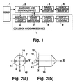
- Fig. 5 shows the constitution of a collision avoidance device and the associated devices of a conventional rendezvous spacecraft.
- numeral 1 represents a navigation sensor (hereinafter referred to as a sensor) for measuring and computing flight conditions of the rendezvous spacecraft, such as a relative position to atarget, a posture, and acceleration.
- Numeral 2 represents a guidance and control device.
- Numeral 3 represents a circuit (hereinafter referred to as a thruster driver for ordinary use) for driving a group of thrusters (hereinafter referred to as a group of thrusters for ordinary use) which generate translation force and triaxial rotation torque in three dime nsional space.
- Numeral 4 represents a group of thrusters for ordinary use.
- Numeral 5 represents a collision avoidance device.
- Numeral 6 represents an abnormality determining circuit.
- Numeral 7 represents an avoidance operation command circuit.
- Numeral 16 represents a circuit (hereinafter referred to as a thruster driver for redundant use) for driving a group of spare thrusters (hereinafter referred to as a group of thrusters for redundant use) which have functions equivalent to those of the group of thrusters for ordinary use.
- Numeral 17 represents the group of thrusters for redundant use whose constitution is same as that of the group of thrusters for ordinary use.
- each of those devices including the collision avoidance device 5 operates in the following manner.
- the guidance and control device 2 computes required controlling force of six degrees of freedom in total concerning position control and triaxial posture control in three dimensional space, and then generates a drive command for each thruster.
- the thruster driver for ordinary use 3 drives the group of thrusters for ordinary use 4 in reply to the aforementioned drive command received. Due to a sequence of the operations, a rendezvous flight to the target is performed. However, if any one of the devices malfunctions, for example, an abnormal operation, such as a cutoff of output from the sensor 1 or an erroneous injection, is carried out, a normal rendezvous flight will not be performed. In a worst case, the chaser spacecraft and the target may collide with each other.
- the abnormality determining circuit 6 selects a signal which the guidance and control device 2 has designated from among monitor signals concerning the flight conditions, such as a relative position, a posture, and acceleration, outputted by the sensor 1. The abnormality determining circuit 6 then compares the signal or a value computed from the signal with a reference value which has been previously set in the abnormality determining circuit 6, thereby performing a repetitive judgement on the presence of abnormality, such as a mechanical failure, an excess of posture error, and a deviation from a predetermined orbit. When any abnormality is found, the avoidance operation command circuit 7 is notified of the incident.
- the avoidance operation command circuit 7 determines how to cope with the situation basing on the contents of the incident notified and a criterion showing a risk of collision, such as an estimated amount of time the spacecraft reaches the target, which is provided by the guidance and control device 2. An outcome of the judgement is transmitted to the guidance and control device 2 as a command to perform the collision avoidance.
- the avoidance operation command circuit 7 determines that any failure arises or may arise in a group of thrusters although there is no sufficient time left before the spacecraft reaches the target, the group of thrusters will be switched to a group of thrusters for redundant use, and a command to perform the injection for collision avoidance will be given to the guidance and control device 2.
- the guidance and control device 2 computes the required controlling force of six degrees of freedom to carry out the injection for collision avoidance and maintain an appropriate posture during the period, and inputs a drive command for each thruster to the thruster driver for redundant use 16. Consequently, a group of thrusters for redundant use 17 are activated and the injection for collision avoidance is finally executed.
- Equation 1 A correlation between a direction of the injection for collision avoidance and an avoidance orbit is shown by an "equation 1.”
- the equation 1 is a so-called Hill equation. This is an equation of motion which shows a relative position of the rendezvous spacecraft to the target by setting the coordinate origin be the target, X-axis be in the direction of the orbit of the target, and Z-axis be in the direction of the center of the earth. (Y-axis, namely, motion in the direction which deviates from the spacecraft's orbital plane is omitted because such motion does not influence collision avoidance.)
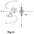
- Fig. 6 illustrate an example of the solution of the equation 1.
- numeral 15 represents the rendezvous spacecraft and numeral 18 represents the target.
- Coordinates X and Z are in the direction of the orbit of the target and the direction of the center of the earth, respectively, as shown in the equation 1. As shown in the drawing, if thrust is applied in the direction of orbit by the injection for collision avoidance, the rendezvous spacecraft 15 will pass over and go away in the backward direction of the target 18. If the thrust is applied in the reverse direction of the orbit, the rendezvous spacecraft 15 will pass below and go away in the forward direction of the target 18.
- the rendezvous spacecraft is usually equipped with at least a group of thrusters for redundant use 17 by way of precaution against a failure of the group of thrusters for ordinary use 4.
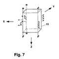
- An example of the arrangement of the groups of thrusters is shown in Fig. 7.
- the constitution of a group of thrusters for rendezvous is such that a mass of thrusters are arranged in a complicated manner.
- a solid line arrow represents one of these thrusters for avoidance
- a dashed line arrow represents one of these thrusters for redundant use.
- Each of these arrows shows a direction of the injection.
- the injection for collision avoidance and the posture control during the injection are carried out by using the group of thrusters for redundant use 17, which have a function to generate three dimensional translation force and triaxial rotation torque, equivalent to the group of thrusters for ordinary use as described above. Consequently, the prior art has superfluous functions for ensuring safety of the rendezvous spacecraft and the target and involves a complicated constitution and a comparatively high cost.
- the present invention is made in order to solve the problems described above. It is directed to provide a system which has simple constitution of thrusters and is not a burden to software by using a group of thrusters which have a minimum of essential function to avoid the collision of a spacecraft (hereinafter referred to as a group of thrusters for collision avoidance) and are independent of a group of thrusters for ordinary use.
- a group of thrusters for collision avoidance a group of thrusters for collision avoidance
- the present invention is related to a device for avoiding the collision of a rendezvous spacecraft.
- the present invention has a plurality of thrusters for collision avoidance separately from thrusters for ordinary use. These thrusters for collision avoidance generate translational thrust and posture control torque around two axes which are orthogonal to a translational thrust axis representing the translational thrust.
- a collision avoidance operation is carried out maintaining the generation of thrust in the direction of a translational thrust vector by driving these thrusters for collision avoidance.
- thrusters for collision avoidance are driven when such a collision is to be avoided.
- decision making on the avoidance is very easy.
- Thrusters only for avoidance are provided, whereby a minimum of thruster necessary for collision avoidance is enough. Therefore, constitution of thrusters can be simplified an d control is easily performed.
- a collision avoidance operation is carried out by rendering at least one of the aforementioned plural thrusters for collision avoidance inactive. Consequently, this leads to an appropriate and easily controllable avoidance operation.
- the aforementioned plural thrusters for collision avoidance consist of at least four thrusterunits. These four thrusters contain a component of translational thrust in their respective outputs. Also, these four thrusters generate posture control torque around those two axes which are orthogonal to the translational thrust axis, and control relative outputs of the plural thrusters for collision avoid ance, whereby a collision avoidance operation is executed.
- the plural thrusters for collision avoidance mentioned above include four pieces of thrusters in the following manner: these four thrusters are arranged on two axes which are orthogonal to the translational thrust axis and also meet each other at right angles at the origin, namely, a certain point of the translational thrust axis; these thrusters are paired and each pair faces each other with the origin as the center; and each of these thrusters outputs thrust in a direction which is parallel to the translational thrust axis.
- the plural thrusters for collision avoidance mentioned above include at least two thrusterunits for translation and at least two thrusterunits for posture control.
- the former are capable of outputting a component of translational thrust and at the same time generating posture control torque around the first axis which is orthogonal to the translational thrust axis.
- the latter independently carry out posture control around the second axis which is orthogonal to both the aforementioned translational thrust axis and the aforementioned first axis.
- the aforementioned thrusters for translation are arranged opposite to each other with a point of intersection of the second axis and the translational thrust axis as the center, and output thrust in a direction which is parallel to the translational thrust axis
- the aforementioned thrusters for posture control are arranged opposite to each other with a point of intersection of the first axis and the translational thrust axis as the center, and output thrust in a reverse direction on the first axis.
- the plural thrusters for collision avoidance mentioned above include at least one thruster for translation which outputs a component of translational thrust and at least four thrusters for posture control which independently carry out posture control around two axes being orthogonal to the translational thrust axis.
- the aforementioned single thruster for translation includes a thruster which is provided on the translational thrust axis and outputs translational thrust
- the aforementioned four thrusters for posture control include a pair of thrusters and another pair of thrusters: the first pair of thrusters are arranged on one of these two axes, which are orthogonal to each other with the translational thrust axis as the origin, in such a manner that these two thrusters face each other with the origin between and output thrust in an opposite direction, respectively; and the second pair of thrusters are arranged on the other one of these two axes, which are orthogonal to each other, in such a manner that these two thrusters face each other with the origin between and output thrust in an opposite direction, respectively.
- Fig. 1 is a block diagram showing an embodiment 1 of the present invention.
- Figs. 2(a) and 2(b) are arrangement drawings of thrusters according to an embodiment 1 of the present invention.
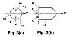
- Figs. 3(a) and 3(b) are arrangement drawings of thrusters according to an embodiment 2 of the present invention.
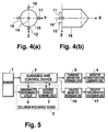
- Figs. 4(a) and 4(b) are arrangement drawings of thrusters according to an embodiment 3 of the present invention.
- Fig. 5 is a block diagram showing a conventional device.
- Fig. 6 shows a correlation between a direction of injection for collision avoidance and an avoidance orbit.
- Fig. 7 shows an example of arrangement of thrusters according to an embodiment of the conventional device.
- Fig. 1 shows a constitution according to an embodiment 1 of the present invention.
- numerals 1 to 4 are the same as those in Fig. 5 which show an embodiment of a conventional device.
- Numeral 5 is a collision avoidance device of the present invention.
- Numeral 6 is an abnormality determining circuit.
- Numeral 7 is an avoidance operation command circuit.
- Numeral 8 is a thruster driver for avoidance.
- Numeral 9 is a group of thrusters for avoidance.
- Figs. 2(a) and 2(b) show an arrangement of a group of those thrusters for avoidance 9 according to the embodiment 1.
- An illustration of a group of thrusters for ordinary use 4 is omitted.
- numerals 10, 11, 13, and 15 represent a first thruster, a second thruster, a fourth thruster, and a rendezvous spacecraft, respectively.
- each of the devices including the collision avoidance device 6 operates in the following manner.
- a guidance and control device 2 computes required control force of six degrees freedom in total concerning position control in three dimensiona l space and triaxial posture control in accordance with a measurement signal from a sensor 1, and generates a drive command for each thruster.
- a thruster driver for ordinary use 3 drives the group of thrusters for ordinary use 4.
- the abnormal ity determining circuit 6 selects a signal designated by the guidance and control device 2 from among monitor signals outputted by the sensor 1 concerning flight conditions, such as a relative position, a posture, and acceleration, and compares the signal or a value calculated from the signal with a reference value previously set in the abnormality determining circuit 6. In such a manner, a repetitive judgement on the presence of abnormality, such as a mechanical failure, an excess of posture error, and a deviation from a predetermined orbit is carried out.
- the avoidance operation command circuit 7 When any abnormality is found, the avoidance operation command circuit 7 is notified of the incident. The avoidance operation command circuit 7 then determines how to cope with the situation based on the contents of the incident notified and a criterion showing a risk of collision, such as an estimated amount of time the spacecraft reaches the target, which is provided by the guidance and control device 2. An outcome of the judgement is transmitted to the guidance and control device 2 as a command to perform the collision avoidance.
- the avoidance operation command circuit 7 determines that a thruster or thrusters are broken or may be broken when there is no sufficient time left before the spacecraft reaches the target, the guidance and control device 2 will receive a command not to send any drive command to the thruster driver for ordinary use, thereby preventing the thrusters for ordinary use from being used.
- the avoidance operation command circuit 7 in accordance with a collision avoidance operation command which the avoidance operation command circuit 7 itself generated, the avoidance operation command circuit 7 generates an injection command corresponding to an equation 3 to the thruster driver for avoidance 8.
- the equation 3 stands for an expression of instruction which brings about the output of translational thrust by using the first thruster 10 to the fourth thruster 14, the generation of torque around an axis Y by using the second thruster 10 or the third thruster 12, and the generation of torque around an axis Z by using the second thruster 11 or the fourth thruster 13 in the arrangement of thrusters of Fig. 2.
- the avoidance operation command circuit 8 drives the group of thrusters for avoidance 9, whereby injection for collision avoidance is carried out with the thrust axis being maintained.
- a definition of the coordinate axes and an arrangement of thrusters shall be based on Fig. 2.
- the injection for collision avoidance and the generation of posture control torque around these two coordinate axes which are orthogonal to the translational thrust axis are carried out by using four pieces of thrusters for avoidance.
- Constitution of an embodiment 2 of the present invention is same as that of the embodiment 1.
- Figs. 3(a) and 3(b) show an arrangement of the group of thrusters for avoidance 9 according to the embodiment 2, respectively.
- numerals 10, 11, 13, and 15 represent the first thruster, the second thruster, the fourth thruster, and the rendezvous spacecraft, respectively.
- Operations in the embodiment 2 correspond to those of the embodiment 1 except that, when any abnormality arises in a thruster or thrusters, the avoidance operation command circuit 7 generates to the thruster driver for avoidance 8 a command to execute injection for collision avoidance which is corresponding to an equation 4.
- the equation 4 stands for an expression of instruction which brings about the output of translational thrust by using the first thruster 10 and the third thruster 12, the generation of torque around the axis Y by using the first thruster 10 or the third thruster 12, and the generation of torque around the axis Z by using the second thruster 11 or the fourth thruster 13 in the arrangement of thrusters shown in Figs. 3(a) and 3(b).
- the avoidance operation command circuit 8 drives the group of thrusters for avoidance 9, whereby injection for collision avoidance is carried out with the thrust axis being maintained.
- a definition of the coordinate axes and an arrangement of thrusters shall be based on Fig. 3.
- a group of thrusters for avoidance are used in such a manner that the injection for collision avoidance and the generation of posture control torque around a coordinate axis which is orthogonal to the translational thrust axis are carried out by using two pieces of thrusters, whereas the generation of posture control torque around the third axis which is orthogonal to the aforementioned two axes is carried out by using two pieces of independent thrusters.
- the generation of posture control torque around the third axis which is orthogonal to the aforementioned two axes is carried out by using two pieces of independent thrusters.
- Constitution of an embodiment 3 of the present invention is the same as that of the embodiment 1.
- Figs. 4(a) and 4(b) show an arrangement of the group of thrusters for avoidance 9 in the embodiment 3, respectively.
- numerals 10, 11, 12, 13, 14, and 15 represent the first thruster, the second thruster, the third thruster, the fourth thruster, the fifth thruster, and the rendezvous spacecraft, respectively.
- the avoidance operation command circuit 7 when any abnormality arises in a thruster or thrusters, the avoidance operation command circuit 7 generates to the thruster driver for avoidance 8 a command to execute injection for collision avoidance which is corresponding to an equation 5.
- the equation 5 stands for an expression of instruction which brings about the output of translational thrust by using the fifth thruster 14, the generation of torque around the axis Y by using the first thruster 10 or the third thruster 12, and the generation of torque around the axis Z by using the second thruster 11 or the fourth thruster 13 in the arrangement of thrusters shown in Figs. 4(a) and 4(b).
- the avoidance operation command circuit 8 drives the group of thrusters for avoidance 9, whereby injection for collision avoidance is carried out with the thrust axis being maintained.
- a group of thrusters for avoidance are used in such a manner that the injection for collision avoidance is carried out by using a piece of thruster, whereas the generation of posture control torque around a coordinate axis which is orthogonal to the translational thrust axis is carried out by using four pieces of independent thrusters.
- the generation of posture control torque around a coordinate axis which is orthogonal to the translational thrust axis is carried out by using four pieces of independent thrusters.
- a group of thrusters for avoidance are used when abnormality arises in a group of thrusters for ordinary use.
- a group of thrusters for avoidance are used as substitutes; and a system in which a group of thrusters for ordinary use and plural groups of thrusters for avoidance are equipped, and even when abnormality arises in a group of thrusters for avoidance which are used as substitutes for a group of thrusters for ordinary use, another group of thrusters for avoidance is used as further substitutes.
Landscapes
- Engineering & Computer Science (AREA)
- Remote Sensing (AREA)
- Aviation & Aerospace Engineering (AREA)
- Chemical & Material Sciences (AREA)
- Combustion & Propulsion (AREA)
- Radar, Positioning & Navigation (AREA)
- Control Of Position, Course, Altitude, Or Attitude Of Moving Bodies (AREA)
Claims (8)
- Kollisionsvermeidungsvorrichtung für ein Rendezvous-Raumfahrzeug mit mehreren Triebwerken für eine Kollisionsvermeidung, welche getrennt von Triebwerken für den gewöhnlichen Gebrauch vorgesehen sind, wobei die Triebwerke für eine Kollisionsvermeidung einen Translationsschub und ein Lagesteuer-Drehmoment um zwei Achsen erzeugen, welche zu einer Translationsschubachse, die den Translationsschub darstellt, orthogonal sind, und wobei, wenn eine Kollisionsvermeidung erforderlich ist, ein Kollisionsvermeidungsvorgang durchgeführt wird unter Aufrechterhaltung der Erzeugung von Schub in einer Richtung eines Translationsschubvektors, indem die Triebwerke für eine Kollisionsvermeidung angetrieben werden.
- Kollisionsvermeidungsvorrichtung für ein Rendezvous-Raumfahrzeug nach Anspruch 1, worin ein Kollisionsvermeidungsvorgang durchgeführt wird, indem zumindest eines der Triebwerke für eine Kollisionsvermeidung inaktiv gemacht wird.
- Kollisionsvermeidungsvorrichtung für ein Rendezvous-Raumfahrzeug nach Anspruch 1 oder 2, worin die Triebwerke für eine Kollisionsvermeidung zumindest vier Triebwerke aufweisen, von denen jedes eine Translationsschubkomponente in seinem Ausgangsschub enthält, ein Lagesteuer-Drehmoment um zwei Achsen, welche orthogonal zu einer Translationsschubachse sind, erzeugt, und relative Ausgangsschübe der Triebwerke für eine Kollisionsvermeidung steuert, wodurch ein Kollisionsvermeidungsvorgang durchgeführt wird.
- Kollisionsvermeidungsvorrichtung für ein Rendezvous-Raumfahrzeug nach Anspruch 3, worin die Triebwerke für eine Kollisionsvermeidung vier Triebwerke in einer solchen Weise enthalten, daß diese vier Triebwerke auf zwei Achsen angeordnet sind, die orthogonal zu einer Translationsschubachse sind und auch einander unter einem rechten Winkel an einem Punkt der Translationsschubachse mit dem Punkt als einem Ursprung treffen; wobei diese vier Triebwerke paarweise angeordnet sind und jedes Paar einander zugewandt ist mit dem Ursprung als einer Mitte; und wobei jedes dieser vier Triebwerke einen Schub in einer Richtung, welche parallel zu der Translationsschubachse ist, ausgibt.
- Kollisionsvermeidungsvorrichtung für ein Rendezvous-Raumfahrzeug nach Anspruch 1 oder 2, worin die Triebwerke für eine Kollisionsvermeidung enthalten: zwei oder mehr Triebwerke für eine Translationsbewegung, welche in der Lage sind, eine Translationsschubkomponente auszugeben und zur selben Zeit ein Lagesteuer-Drehmoment um eine erste Achse, die orthogonal zu einer Translationsschubachse ist, zu erzeugen; und zwei oder mehr Triebwerke für eine Lagesteuerung, welche unabhängig eine Lagesteuerung um eine zweite Achse, welche orthogonal sowohl zu der Translationsschubachse und der ersten Achse ist, ausführen.
- Kollisionsvermeidungsvorrichtung für ein Rendezvous-Raumfahrzeug nach Anspruch 5, worin die Triebwerke für eine Translationsbewegung einander gegenüber angeordnet sind mit einem Schnittpunkt der zweiten Achse und der Translationsschubachse als Mitte, und einen Schub in einer Richtung ausgeben, welche parallel zu der Translationsschubachse ist, wohingegen die Triebwerke für eine Lagesteuerung einander gegenüber angeordnet sind mit einem Schnittpunkt der ersten Achse und der Translationsschubachse als Mitte, und einen Schub in einer umgekehrten Richtung auf der ersten Achse ausgeben.
- Kollisionsvermeidungsvorrichtung für ein Rendezvous-Raumfahrzeug nach Anspruch 1 oder 2, worin die Triebwerke für eine Kollisionsvermeidung zumindest ein Triebwerk für eine Translationsbewegung, welches eine Translationsschubkomponente ausgibt, und zumindest vier Triebwerke für eine Lagesteuerung, welche unabhängig eine Lagesteuerung um zwei Achsen, welche orthogonal zu einer Translationsschubachse sind, ausführen, enthalten.
- Kollisionsvermeidungsvorrichtung für ein Rendezvous-Raumfahrzeug nach Anspruch 7, bei welcher das Triebwerk für eine Translationsbewegung ein einzelnes Triebwerk enthält, das auf einer Translationsschubachse vorgesehen ist und einen Schub ausgibt, wohingegen die Triebwerke für eine Lagesteuerung enthalten: ein Paar von Triebwerken, welche auf einer von zwei Achsen angeordnet sind, die orthogonal zueinander mit der Translationsschubachse als ein Ursprung sind, in einer solchen Weise, daß diese beiden Triebwerke einander zugewandt sind mit dem Ursprung dazwischen, und Schub in einer entgegengesetzten Richtung ausgeben; und ein anderes Paar von Triebwerken, welche auf der anderen der beiden Achsen angeordnet sind, die orthogonal zueinander in einer solchen Weise sind, daß diese beiden Triebwerke einander zugewandt sind mit den Ursprung dazwischen, und Schub in einer entgegengesetzten Richtung ausgeben.
Applications Claiming Priority (3)
| Application Number | Priority Date | Filing Date | Title |
|---|---|---|---|
| JP100557/96 | 1996-04-22 | ||
| JP10055796 | 1996-04-22 | ||
| JP10055796A JP3867315B2 (ja) | 1996-04-22 | 1996-04-22 | 自動衝突回避装置 |
Publications (2)
| Publication Number | Publication Date |
|---|---|
| EP0803436A1 EP0803436A1 (de) | 1997-10-29 |
| EP0803436B1 true EP0803436B1 (de) | 2001-07-18 |
Family
ID=14277243
Family Applications (1)
| Application Number | Title | Priority Date | Filing Date |
|---|---|---|---|
| EP97106540A Expired - Lifetime EP0803436B1 (de) | 1996-04-22 | 1997-04-21 | Gerät zur Vermeidung von Raumfahrzeugkollisionen beim Rendezvousmanöver |
Country Status (4)
| Country | Link |
|---|---|
| US (1) | US5868358A (de) |
| EP (1) | EP0803436B1 (de) |
| JP (1) | JP3867315B2 (de) |
| DE (1) | DE69705665T2 (de) |
Families Citing this family (15)
| Publication number | Priority date | Publication date | Assignee | Title |
|---|---|---|---|---|
| WO2000013971A2 (en) * | 1998-06-02 | 2000-03-16 | Galaxy Development Llc | Fast resonance shifting as a way to reduce propellant for space mission applications |
| US20040254728A1 (en) * | 2002-10-25 | 2004-12-16 | Poropat George Vladimir | Collision warning system and method |
| US6945500B2 (en) * | 2003-08-15 | 2005-09-20 | Skycorp, Inc. | Apparatus for a geosynchronous life extension spacecraft |
| FR2897841B1 (fr) * | 2006-02-27 | 2009-02-27 | Univ Paris Curie | Engin spatial et procede pour faire fonctionner l'engin spatial. |
| EP1936584B1 (de) * | 2006-12-22 | 2010-03-10 | Saab Ab | Vorrichtung an einem Flugkörper und Verfahren zur Kollisionsvermeidung |
| US8833702B2 (en) * | 2012-05-07 | 2014-09-16 | Robert Briskman | Autonomous satellite orbital debris avoidance system and method |
| US20150001344A1 (en) * | 2013-06-26 | 2015-01-01 | Raytheon Company | Satellite positioning system |
| US9963249B2 (en) * | 2015-06-29 | 2018-05-08 | The Boeing Company | Efficient stationkeeping design for mixed fuel systems in response to a failure of an electric thruster |
| CN106707751B (zh) * | 2016-12-20 | 2019-05-17 | 哈尔滨工业大学 | 航天器终端接近的有限时间饱和避碰控制方法 |
| FR3076817B1 (fr) * | 2018-01-16 | 2020-02-14 | Arianegroup Sas | Procede d'ejection d'une charge utile depuis un vehicule spatial anime d'une force de propulsion continue |
| CN109696917A (zh) * | 2019-01-28 | 2019-04-30 | 中国人民解放军军事科学院国防科技创新研究院 | 一种航天器自动交会避障方法及系统 |
| US11807404B2 (en) * | 2020-06-28 | 2023-11-07 | Mitsubishi Electric Research Laboratories Inc. | Abort-safe vehicle rendezvous in case of partial control failure |
| US11987396B2 (en) * | 2020-06-28 | 2024-05-21 | Mitsubishi Electric Research Laboratories Inc. | Fail-safe vehicle rendezvous in case of total control failure |
| CN112000132A (zh) * | 2020-07-08 | 2020-11-27 | 中国人民解放军军事科学院国防科技创新研究院 | 基于椭球体描述的航天器避障控制方法 |
| US12312102B2 (en) * | 2021-12-10 | 2025-05-27 | Mitsubishi Electric Research Laboratories, Inc. | System and method for controlling a motion of a spacecraft in a multi-object celestial system |
Family Cites Families (10)
| Publication number | Priority date | Publication date | Assignee | Title |
|---|---|---|---|---|
| IT1193427B (it) * | 1983-04-19 | 1988-06-22 | Ritalia Societa Aerospaziale I | Sistema di aggancio docking per moduli spaziali |
| US4834531A (en) * | 1985-10-31 | 1989-05-30 | Energy Optics, Incorporated | Dead reckoning optoelectronic intelligent docking system |
| JP2635746B2 (ja) * | 1987-09-16 | 1997-07-30 | メッセルシュミット‐ベルコウ‐ブローム・ゲゼルシャフト・ミト・ベシュレンクテル・ハフツング | 角運動量を蓄えた自由運動体の目標値制御および/または安定化を行う装置 |
| US4961551A (en) * | 1988-11-18 | 1990-10-09 | Hughes Aircraft Company | Stabilization of a spinning spacecraft of arbitary shape |
| US5109345A (en) * | 1990-02-20 | 1992-04-28 | The United States Of America As Represented By The Administrator Of The National Aeronautics And Space Administration | Closed-loop autonomous docking system |
| DE4129627C2 (de) * | 1991-09-06 | 1994-08-04 | Deutsche Aerospace | Vorrichtung und Verfahren zur Lageregelung eines um eine körperfeste Achse in Rotation zu versetzenden Raumfahrzeuges |
| JP2669223B2 (ja) * | 1991-10-14 | 1997-10-27 | 三菱電機株式会社 | ランデブードッキング用光学センサー装置 |
| US5279484A (en) * | 1992-03-11 | 1994-01-18 | Loral Aerospace Corporation | Manned space vehicle with low-level hydrogen-oxygen-carbon dioxide propulsion unit |
| US5294079A (en) * | 1992-04-01 | 1994-03-15 | Trw Inc. | Space transfer vehicle |
| US5335179A (en) * | 1992-12-24 | 1994-08-02 | General Electric Co. | Unified spacecraft attitude control system with pseudo-complementary paired thrusters |
-
1996
- 1996-04-22 JP JP10055796A patent/JP3867315B2/ja not_active Expired - Lifetime
-
1997
- 1997-04-18 US US08/844,243 patent/US5868358A/en not_active Expired - Lifetime
- 1997-04-21 EP EP97106540A patent/EP0803436B1/de not_active Expired - Lifetime
- 1997-04-21 DE DE69705665T patent/DE69705665T2/de not_active Expired - Lifetime
Also Published As
| Publication number | Publication date |
|---|---|
| DE69705665T2 (de) | 2002-05-23 |
| DE69705665D1 (de) | 2001-08-23 |
| US5868358A (en) | 1999-02-09 |
| EP0803436A1 (de) | 1997-10-29 |
| JPH09286400A (ja) | 1997-11-04 |
| JP3867315B2 (ja) | 2007-01-10 |
Similar Documents
| Publication | Publication Date | Title |
|---|---|---|
| EP0803436B1 (de) | Gerät zur Vermeidung von Raumfahrzeugkollisionen beim Rendezvousmanöver | |
| JP2844090B2 (ja) | 静止衛星のための姿勢制御システム | |
| JP7621533B2 (ja) | 衝突回避方法および地上設備 | |
| EP0781706A2 (de) | Verfahren zur systematischen Kalibrierung von der vektoriellen Schubkraft für Momentumsregelung eines Satelliten | |
| Ueda et al. | HTV rendezvous technique and GN&C design evaluation based on 1st flight on-orbit operation result | |
| US12454370B2 (en) | Satellite constellation maintaining method, satellite constellation, orbital dropping method, and artificial satellite | |
| Kawano et al. | In-orbit demonstration of an unmanned automatic rendezvous and docking system by the Japanese engineering test satellite ETS-VII | |
| Seweryn et al. | The prototype of space manipulator WMS LEMUR dedicated to capture tumbling satellites in on-orbit environment | |
| JP2023018562A (ja) | 衛星コンステレーション、通信衛星および自動衝突回避方法 | |
| Zhang et al. | Predictive control of teleoperation rendezvous with large time delay | |
| CN113320717A (zh) | 一种应对一次点火故障的制导系统重构方法 | |
| Gambone | Seeker Cubesat Control System | |
| RU2205139C2 (ru) | Способ управления пилотируемым космическим аппаратом, отстыкованным от находящегося на околокруговой орбите неориентированного космического объекта | |
| Mokuno et al. | Development of ETS-VII RVD system-Preliminary design and EM development phase (Engineering Test Satellite and RendezVous Docking) | |
| Baranov et al. | Controlling the motion of a spacecraft when approaching a large object of space debris | |
| Ito et al. | Reliable and robust implementation of attitude determination and control subsystem and initial flight operation results of 50-kg class interplanetary spacecraft Procyon | |
| Hamed et al. | Multiple Debris Orbital Collision Avoidance | |
| Dennehy et al. | Guidance, navigation and control (GN&C) best practices for human-rated spacecraft systems | |
| JP2979906B2 (ja) | 宇宙機の誘導装置 | |
| Aghilia | Active Debris Removal (ADR): A Remedial Strategy for Sustainable Satellite Operations | |
| US7114684B2 (en) | Method, apparatus, and computer program product for safe exit maneuver from dimensionally extended rotating space vehicle | |
| Ueda et al. | HTV guidance, navigation and control system design for safe robotics capture | |
| Lebsock et al. | Guidance, Navigation and Control (GN&C): Best Practices for Human-Rated Spacecraft Systems | |
| Woo et al. | Integrated system technology in a launch vehicle integrated testbed | |
| JUDD | Optimized redundant avionics for IUS protects high cost space missions |
Legal Events
| Date | Code | Title | Description |
|---|---|---|---|
| PUAI | Public reference made under article 153(3) epc to a published international application that has entered the european phase |
Free format text: ORIGINAL CODE: 0009012 |
|
| AK | Designated contracting states |
Kind code of ref document: A1 Designated state(s): DE FR |
|
| 17P | Request for examination filed |
Effective date: 19971104 |
|
| GRAG | Despatch of communication of intention to grant |
Free format text: ORIGINAL CODE: EPIDOS AGRA |
|
| GRAG | Despatch of communication of intention to grant |
Free format text: ORIGINAL CODE: EPIDOS AGRA |
|
| GRAH | Despatch of communication of intention to grant a patent |
Free format text: ORIGINAL CODE: EPIDOS IGRA |
|
| 17Q | First examination report despatched |
Effective date: 20001122 |
|
| GRAH | Despatch of communication of intention to grant a patent |
Free format text: ORIGINAL CODE: EPIDOS IGRA |
|
| GRAA | (expected) grant |
Free format text: ORIGINAL CODE: 0009210 |
|
| AK | Designated contracting states |
Kind code of ref document: B1 Designated state(s): DE FR |
|
| REF | Corresponds to: |
Ref document number: 69705665 Country of ref document: DE Date of ref document: 20010823 |
|
| ET | Fr: translation filed | ||
| PLBE | No opposition filed within time limit |
Free format text: ORIGINAL CODE: 0009261 |
|
| STAA | Information on the status of an ep patent application or granted ep patent |
Free format text: STATUS: NO OPPOSITION FILED WITHIN TIME LIMIT |
|
| 26N | No opposition filed | ||
| REG | Reference to a national code |
Ref country code: FR Ref legal event code: PLFP Year of fee payment: 20 |
|
| PGFP | Annual fee paid to national office [announced via postgrant information from national office to epo] |
Ref country code: FR Payment date: 20160309 Year of fee payment: 20 |
|
| PGFP | Annual fee paid to national office [announced via postgrant information from national office to epo] |
Ref country code: DE Payment date: 20160412 Year of fee payment: 20 |
|
| REG | Reference to a national code |
Ref country code: DE Ref legal event code: R071 Ref document number: 69705665 Country of ref document: DE |