EP0803433B1 - Heat sealable inflator - Google Patents
Heat sealable inflator Download PDFInfo
- Publication number
- EP0803433B1 EP0803433B1 EP96106490A EP96106490A EP0803433B1 EP 0803433 B1 EP0803433 B1 EP 0803433B1 EP 96106490 A EP96106490 A EP 96106490A EP 96106490 A EP96106490 A EP 96106490A EP 0803433 B1 EP0803433 B1 EP 0803433B1
- Authority
- EP
- European Patent Office
- Prior art keywords
- bore
- gas
- inflatable article
- pierce pin
- gasket
- Prior art date
- Legal status (The legal status is an assumption and is not a legal conclusion. Google has not performed a legal analysis and makes no representation as to the accuracy of the status listed.)
- Expired - Lifetime
Links
- 238000010304 firing Methods 0.000 claims abstract description 27
- 239000000463 material Substances 0.000 claims abstract description 21
- 238000007789 sealing Methods 0.000 claims description 14
- 238000000034 method Methods 0.000 claims description 8
- 239000012530 fluid Substances 0.000 claims 1
- 238000004519 manufacturing process Methods 0.000 abstract description 7
- 230000011664 signaling Effects 0.000 abstract description 5
- 239000004033 plastic Substances 0.000 abstract description 4
- 229920003023 plastic Polymers 0.000 abstract description 4
- 239000004721 Polyphenylene oxide Substances 0.000 abstract description 3
- 229920000728 polyester Polymers 0.000 abstract description 3
- 229920000570 polyether Polymers 0.000 abstract description 3
- 229920002635 polyurethane Polymers 0.000 abstract description 3
- 239000004814 polyurethane Substances 0.000 abstract description 3
- 230000006835 compression Effects 0.000 description 8
- 238000007906 compression Methods 0.000 description 8
- 239000002184 metal Substances 0.000 description 6
- 230000000712 assembly Effects 0.000 description 4
- 238000000429 assembly Methods 0.000 description 4
- 238000011065 in-situ storage Methods 0.000 description 4
- CURLTUGMZLYLDI-UHFFFAOYSA-N Carbon dioxide Chemical compound O=C=O CURLTUGMZLYLDI-UHFFFAOYSA-N 0.000 description 2
- 238000010276 construction Methods 0.000 description 2
- 238000001746 injection moulding Methods 0.000 description 2
- XLYOFNOQVPJJNP-UHFFFAOYSA-N water Substances O XLYOFNOQVPJJNP-UHFFFAOYSA-N 0.000 description 2
- 230000009286 beneficial effect Effects 0.000 description 1
- 229910002092 carbon dioxide Inorganic materials 0.000 description 1
- 239000001569 carbon dioxide Substances 0.000 description 1
- 239000002131 composite material Substances 0.000 description 1
- IWEDIXLBFLAXBO-UHFFFAOYSA-N dicamba Chemical compound COC1=C(Cl)C=CC(Cl)=C1C(O)=O IWEDIXLBFLAXBO-UHFFFAOYSA-N 0.000 description 1
- 230000009977 dual effect Effects 0.000 description 1
- 229920001971 elastomer Polymers 0.000 description 1
- 238000002347 injection Methods 0.000 description 1
- 239000007924 injection Substances 0.000 description 1
- 238000009434 installation Methods 0.000 description 1
- 230000013011 mating Effects 0.000 description 1
Images

Classifications
-
- B—PERFORMING OPERATIONS; TRANSPORTING
- B63—SHIPS OR OTHER WATERBORNE VESSELS; RELATED EQUIPMENT
- B63C—LAUNCHING, HAULING-OUT, OR DRY-DOCKING OF VESSELS; LIFE-SAVING IN WATER; EQUIPMENT FOR DWELLING OR WORKING UNDER WATER; MEANS FOR SALVAGING OR SEARCHING FOR UNDERWATER OBJECTS
- B63C9/00—Life-saving in water
- B63C9/24—Arrangements of inflating valves or of controls thereof
Definitions
- This invention relates to an inflator for inflating articles such as personal floatation devices, rafts, buoys, and emergency signalling equipment, whose housing may be directly heat-sealed to the inflatable article while assuring that the inflatable article remains inflated even when gas cartridge of the inflator is removed and a method for inflating an inflatable article with gas from a gas cartridge.
- Inflators designed to inflate inflatable articles such as personal floatation devices (life vests, rings and horseshoes), life rafts, buoys and emergency signalling equipment.
- Inflators typically comprise a body for receiving the neck of a cartridge of compressed gas such as carbon dioxide.
- a reciprocating pierce pin is disposed within the body of the inflator for piercing frangible seal of the cartridge to permit compressed gas therein to flow into a manifold assembly of the inflator and then into the article to be inflated.
- a manually movable firing lever is operatively connected to the piercing pin such that the piercing pin pierces the frangible seal of the cartridge upon jerking of a ball lanyard.
- U.S. Patent Number 3,809,288 illustrates one particular embodiment of a manual inflator.
- Water-activated actuators have been incorporated into manual inflators so that in an emergency situation such as downed aviator, injured person or a man overboard, the inflator is automatically actuated to inflate the inflatable article to which it is connected.
- Representative automatic actuators for inflators are disclosed in U.S. Patent Numbers 3,059,814, 3,091,782, 3,426,942, 3,579,964, 3,702,014, 3,757,371, 3,910,457, 3,997,079, 4,223,805, 4,267,944, 4,260,075, 4,382,231, 4,436,159, 4,513,248, 4,627,823, and 5,076,468.
- inflators are typically connected to the inflatable article by means of the manifold assembly that consists of a metal manifold having a lower flange which is molded in situ with a rubber flange.
- a one-way valve such as a schraeder valve, is installed in the manifold.
- a hole is formed in the inflatable article and the manifold is positioned therethrough.
- the flange of the manifold assembly is then heat-sealed to the wall of the inflatable article.
- the one-way valve in the manifold permits inflation of the inflatable article while precluding deflation once inflated.
- typical inflators comprise a manifold hole which is configured and dimensioned to receive the manifold of the manifold assembly.
- a locking nut is threaded onto the end of the manifold to secure the inflator.
- An 0-ring seal is provided to prevent leakage between the manifold and the inflator.
- gas from the compressed gas cartridge flows into the manifold hole of the inflator and then into the manifold.
- the gas then flows past the one-way valve in the manifold and into the inflatable article. Since the one-way valve of the manifold assembly precludes deflation of the inflatable article, the gas cartridge may be removed from the inflator and the inflatable article will remain inflated.
- U.S. Patent 4,894,036 shows an inflator which may be heat-sealed directly to an inflatable article thereby obviating the need for manifold assemblies and the like.
- the heat-sealable inflator as shown in such patent includes a mounting flange integrally formed about the housing of the inflator.
- the housing together with the integral mounting flange are composed of a plastic or similar material which may be heat-sealed to inflatable articles composed of conventional plastic or other materials.
- the housing includes a reciprocal pierce pin and a firing lever.
- a pair of compression springs are provided at opposing ends of the pierce pin to exert forces thereon in opposite directions.
- a pair of O-rings are also provided at opposing ends of the pierce pin.
- the cammed end thereof exerts a force on the rearward (stronger) spring and causes the pierce pin to move forwardly and pierce the gas cartridge.
- the cammed end of the manual firing lever is configured such that upon further movement of the lever, the pierce pin may be blown-back fully rearwardly by means of the forward (weaker) compression spring combined with the pressure exerted by the gas from the gas cartridge.
- the bore of the housing in which the pierce pin is reciprocatably positioned is configured in such a manner that when the pierce pin is blown-back fully rearwardly, the gas may flow through a port into the inflatable article.
- the lost pressure allows the rearward (stronger) spring to return the pierce pin assembly to its rest position.
- the bore of the housing is configured so that when the pierce pin is in its rest position, the O-rings seal the port both forwardly and rearwardly in the bore thereby precluding the gas from the inflatable article from escaping.
- Another object of this invention is to provide a heat-sealable inflator for inflatable articles having a housing with a mounting flange integral thereto, the housing and the flange being composed of a material that is capable of being easily sealed to the type of materials that are typically utilized in the construction of inflatable articles.
- Another object of this invention is to provide a heat-sealable inflator which utilizes a minimal number of components and is therefore economical to manufacture.
- Another object of this invention is to provide a heat-sealable inflator having a design which precludes deflation of the inflatable article once inflated even if the gas cartridge threaded into the housing is removed.
- Another object of this invention is to provide a heat-sealable inflator having a design which eliminates a condition of non-inflation even if the firing lever thereof does not move through its full path of travel.
- Another object of this invention is to provide a heat-sealable inflator for inflating an inflatable article with gas from a gas cartridge, comprising in combination: an inflator housing including a bore; means at one end of the bore for receiving the gas cartridge; a pierce pin assembly which is reciprocatably positioned within the bore; means at another end of the bore for actuating the pierce pin assembly to allow gas from the gas'cartridge to flow into the bore; means for fluidly connecting the bore to the inflatable article to allow the gas to inflate the inflatable article; and the pierce pin assembly comprising rear seal means for sealing a rearward portion of the bore and a slidable seal assembly means capable, during inflation of the inflatable article, of being blown-back by the pressure of the gas from the gas cartridge and, after inflation, forming a seal with a forward portion of the bore to prevent the gas in the inflatable article from escaping therefrom forwardly through the bore.
- Another object of this invention is to provide a method for inflating an inflatable article with gas from a gas cartridge, comprising the steps of: providing an inflator housing including a bore; receiving the gas cartridge at one end of the bore; reciprocatably positioning a pierce pin assembly within the bore; actuating the pierce pin assembly to allow gas from the gas cartridge to flow into the bore; fluidly connecting the bore to the inflatable article to allow the gas to inflate the inflatable article; and sealing a rearward portion of the bore and, after inflation, forming a seal with a forward portion of the bore to prevent the gas in the inflatable article from escaping therefrom forwardly through the bore.
- this invention comprises an inflator adapted to be heat-sealed directly to an inflatable article thereby obviating the need for inflation manifolds and the like.
- the inflator of the invention comprises a housing having an integrally formed mounting flange.
- the housing and the mounting flange are formed by injection molding or the like and are composed of a plastic material such as polyurethane, polyester or polyether capable of being easily sealed to the materials conventionally used in the manufacture of inflatable articles such as personal floatation devices, rafts, buoys and emergency signalling equipment.
- a pierce pin assembly is reciprocatably mounted within a bore in the housing.
- a firing lever is pivotably connected to the rear of the housing in alignment with the rearward end of the bore.
- a threaded metal insert for receiving a conventional gas cartridge is molded in situ within the forward end of the bore.
- the firing lever is operatively configured such that upon pivotable movement by means of a lanyarded ball, the pierce pin assembly is forced forwardly within the bore to pierce the frangible seal of the gas cartridge threaded into the metal insert.
- the gas in the gas cartridge escapes into the bore and then into the inflatable article via a port formed within the housing from the bore to the exterior of the housing at a position located interially of the inflatable article, thereby inflating the inflatable article.
- An important feature of the present invention is the pierce pin assembly which is configured in such a manner that it precludes escaping of the gas from the gas cartridge from the bore during inflation thereby causing all of the gas to flow into the inflatable article via the port.
- the configuration of the pierce pin assembly additionally functions to seal that portion of the bore forwardly of the port after the gas escapes from the gas cartridge into the inflatable article. The gas contained within the inflatable article is therefore precluded from escaping from the inflator even if the gas cartridge is removed after inflation.
- the particular configuration of the pierce pin assembly of the invention functions as a one-way valve permitting inflation of the inflatable article and precluding deflation thereof once inflated.
- the pierce pin assembly of the invention utilizes a single compression spring in combination with a conventional 0-ring positioned about its rearward portion and novel sliding seal assembly positioned about the pierce pin at its forward portion.
- the sliding seal assembly functions as a check valve to permit inflation of the inflatable article and to preclude deflation once inflated.
- the sliding seal assembly may comprise several embodiments without departing from the spirit and scope of this invention.
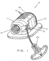
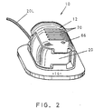
- the inflator 10 of the invention comprises a generallyrectangular-shaped inflator housing 12 having a mounting flange 14 formed annularly about one side thereof.
- the housing 12 and its mounting flange 14 are integrally formed together of a material that is capable of being readily sealed with the material of an inflatable article.
- the material constituting the housing 12 and the flange 14 comprises a material such as polyurethane, polyester or polyether, each of which are known to be readily sealable, such as by radio frequency sealing, to materials conventionally used in the manufacture of inflatable articles such as personal floatation devices, life rafts, buoys and emergency signalling equipment.
- a pierce pin assembly is reciprocably mounted within a longitudinal bore, generally indicated by numeral 18, of the inflator housing 12.
- a firing lever generally indicated by numeral 20, is pivotally mounted at the rearward portion of the inflator housing 12 in alignment with the pierce pin assembly 16.
- a lanyarded handle 20L is connected to the lever 20.
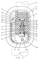
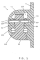
- a conventional metal insert 22, having interior threads and gasket 22G, is molded in situ within the forward portion of the inflator housing 12. As shown in phantom in Fig. 3, a gas cartridge 24 containing compressed gas may be threaded into the metal insert 22. Gasket 22G assures that the gas cartridge 24 is sealed within the insert 22.
- a bleed port 26 extends through the inflator housing 12 from the longitudinal bore 18 to the exterior of the housing 12 at the flanged side thereof such that the lead port 26 leads into the inside of the inflatable article when the inflator 12 is heat-sealed thereto.
- the pierce pin assembly 16 of the invention comprises a generally cylindrical body portion 28 having a rounded rearward end 30.
- the body portion 28 further includes an annular slot 32 for receiving a conventional O-ring 34 that seals against the lumen 18L of the longitudinal bore 18 to preclude the escape of gas rearwardly from the bore 18.
- the pierce pin assembly 16 further includes a pierce pin 36, having a generally cylindrical configuration with a diameter substantially less than the diameter of the cylindrically configured body portion 28.
- the pierce pin 36 extends concentrically from the forward end 38 of the body portion 28 into a reduced diameter portion 18R of the longitudinal bore 18 that includes bleed channels 18C along the length thereof.
- the forward end of the pierce pin 40 is formed at an angle to define a point 42 for piercing the frangible seal of the gas cartridge 24.
- the pierce pin 36 includes a longitudinal slot 44 that extends longitudinally along the pierce pin 36 from the point 42.
- the longitudinal slot 44 extends rearwardly along the pierce pin 36 by a distance that, one the one hand, is sufficiently long to remain in the gas cartridge 24 after piercing and during movement of the pierce pin assembly 16, thereby assuring that the gas cartridge 24 can be fully spent and, on the other hand, sufficiently short not to be engaged by the sliding seal assembly 46 that otherwise could cause damage thereto.
- the pierce pin assembly 16 further includes a slidable seal assembly 46 positioned about the rearward portion of the pierce pin 36.
- the slidable seal assembly 46 functions to permit inflation of the inflatable article and preclude deflation thereof even if the gas cartridge 24 is removed. Generally, these functions are performed by the slidable seal assembly 46 that, in its non-fired position, forms a forward seal within the longitudinal bore 18 forwardly of the bleed port 26.
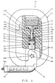
- the slidable seal assembly 46 blows-back in a rearward direction along the length of the pierce pin 36 such that the forward seal is broken allowing the escaping gas from the gas cartridge 24 to bleed into the inflatable article via the bleed port 26.
- the slidable seal assembly 46 is urged forwardly by means of a compression spring 48 along the length of the pierce pin 36 to form the forward seal within the longitudinal bore 18 forwardly of the bleed port 26, thereby precluding gas within the inflatable article from escaping to the atmosphere via the bleed port 26 and longitudinal port 18.
- Figs. 6A, 6B, 6C and 6D illustrate four embodiments of the slidable seal assembly 46.
- the slidable seal assembly 46 includes a gasket 50 adhered or bonded to a rigid gasket retainer 52, both being of substantially cylindrical disk-shaped configuration and configured to be positioned within the longitudinal bore 18 of the housing 12.
- the rigid gasket retainer 52 includes a center hole 54 having a diameter appreciably greater than the diameter of the pierce pin 36 to permit free movement of the retainer 52 longitudinally along the length of the pierce pin 36.
- the gasket 50 also includes a center hole 56.
- the center hole 56 of gasket 50 includes a diameter appreciably less than the diameter of the pierce pin 36 such that an air-tight seal is formed therewith while permitting the gasket 50 to move sealingly along the length of the pierce pin 36.
- the gasket 50 additionally forms a seal, when urged forwardly, with the step 18S formed in the longitudinal bore 18 at the juncture with the reduce diameter portion 18R of the bore 18.
- the rigid gasket retainer 52 comprises a generally disk-shaped configuration with a forwardly protruding annular rim 58 that encircles the gasket 50.
- the step portion 18S of the bore 18 is formed with a rearwardly extending annular protrusion 60 which forms an air-tight seal with the forward surface of the gasket 50 when urged forwardly by the compression spring 48.
- the annular rim 58 of the retainer 52 provides additional support for the gasket 50 to assure that the gasket does not become deformed when sealed against the annular protrusion 60 by the compression spring 48.
- Fig. 6B illustrates another embodiment of the slidable seal assembly 46, which is substantially similar to the embodiment shown in Fig. 6A, but with a rigid gasket retainer 52 that does not include an annular rim 58.
- the material constituting the gasket 50 may be composed of a harder material to eliminate the need for the annular rim 58 providing the extra support.
- the third embodiment of the slidable seal assembly 46 includes a similarly configured rigid gasket retainer 52 to which is adhered or bonded a gasket 50.
- gasket 50 includes a rearwardly extending annular rim 62 which encircles the circumferential edge 50E of the retainer 52 and forms a seal with the lumen 18L of the longitudinal bore 18. It is noted that the gasket 50 with its annular rim 62 is adhered or bonded not only to the front surface of the retainer 52 but also, preferably, adhered or bonded to the circumferential edge 50E of the retainer 52 such that the gasket 50 and its annular rim 62 are fully supported by the retainer 52.
- gasket 50 with its annular rim 62 is appropriately dimensioned to not only form a sliding seal with the pierce pin 36, but to also form a sliding seal with the lumen 18L of the longitudinal bore 18.
- the forward seal forward in the longitudinal bore 18 is not broken until the gasket 50 is blown-back to or past the port 26.
- gasket 50 is preferably composed of a relatively low durometer material capable of maintaining its sealing properties across wide temperature extremes. Therefore, as noted above, it has been found that the gasket 50 is preferably adhered or bonded to the rigid gasket retainer 52 so that the gasket 50 retains its shape and does not fold or otherwise become deformed within the longitudinal bore 18. Notwithstanding, it is also noted that when the inflator 10 of the invention is utilized in less demanding temperature extremes, the gasket 50 may be composed of a material of sufficient durometer that it need not be adhered or bonded to the retainer 52. Indeed, it is contemplated that the need for the retainer 52 may be eliminated altogether when the gasket 50 is composed of a material (or a composite of materials) with sufficient rigidity to withstand the force of the spring 48.
- the firing lever 20 is positioned within a slot 20S formed along the side of the inflator housing 12.
- the exterior surfaces of the inflator housing 12 and the firing lever 20 are formed with a smooth, aesthetically-pleasing rounded contours.
- a pivot pin 66 extends into a blind hole 12H in the inflator housing 12 through a hole 20H of the firing lever 20 such that the firing lever 20 is pivotally secured in operative position for engaging the rearward end 30 of the body portion 28.
- protrusions 20P function to provide bearing surfaces with the mating surfaces 68 of the inflator housing 12, thereby facilitating easier pivoting of the firing lever 20 with reduced friction.
- the gasket 50 then seals against the annular protrusion 60 of the step 18S.
- gasket 50 moves forwardly past the bleed port 26 thereby sealing the bore 18 via the annular rim 62 of the gasket 50. It is noted that in each embodiment the length of the port 26 is such that the gas cartridge 24 is almost completely expended at the point the gasket 50 moves forwardly beyond the port 26.
- the greater the pressure of the gas in the inflatable article the greater force is exerted on the retainer 52 thereby increasing the sealing capabilities of the gasket 50.
- the pierce pin assembly 16 is returned to its non-fired position as shown in Fig. 3 with gasket 50 still maintaining its seal within the bore 18. Accordingly, the spent gas cartridge 24 may be removed without causing deflation of the inflatable article.
- inflator 10 of the invention may be more economically manufactured than all known prior art inflators.
- core-outs 70 should be provided in the inflator housing 12 to assure more accurate injection molding while reducing the quantity of injection material consumed.
- a pop-out (or breakaway) indicator clip 72 may be provided to indicate a fired condition of the inflator 10.
- an automatic actuator 74 may be operatively connected to the inflator 10 to provide for automatic inflation.
Landscapes
- Engineering & Computer Science (AREA)
- Mechanical Engineering (AREA)
- Ocean & Marine Engineering (AREA)
- Air Bags (AREA)
Abstract
Description
Claims (16)
- An inflator (10) for inflating an inflatable article with gas from a gas cartridge (24), comprising in combination:an inflator housing (12) including a bore(18); means (22) at one end of said bore for receiving the gas cartridge; a pierce pin assembly (16) reciprocatably positioned within said bore; means (20) at another end of said bore for actuating said pierce pin assembly to allow gas from the gas cartridge to flow into said bore; means (14) for fluidly connecting said bore to the inflatable article to allow the gas to inflate the inflatable article, said fluid connection means comprising a flange integrally formed about the periphery of said inflator housing, said flange being heat sealable with the inflatable article such that said inflator housing may be positioned about an aperture in the inflatable article and said flange heat sealed to the inflatable article about the aperture; and said pierce pin assembly comprising a pierce pin (36), rear seal means (34) for sealing a rearward portion of said bore and a seal assembly means (46) slidable along said pierce pin and cabable, during inflation of the inflatable article, of being blown-back along said pierce pin by the pressure of the gas from the gas cartridge and, after inflation, sliding along said pierce pin and forming a seal with a forward portion of said bore to prevent the gas in the inflatable article from escaping therefrom forwardly through said bore (18).
- Inflator according to Claim 1, characterized in that said slidable seal assembly (46) comprises a gasket (50) and means for urging said gasket (50) forwardly to form a seal with said forward portion of said bore (18).
- An inflator (10) for inflating an inflatable article with gas from a gas cartridge (24), comprising in combination: an inflator housing (12) including a bore (18); means (22) at one end of said bore for receiving the gas cartridge; a pierce pin assembly (16) which is reciprocatably positioned within said bore; means (20) at another end of said bore for actuating said pierce pin assembly to allow gas from the gas cartridge to flow into said bore; means (14) for fluidly connecting said bore to the inflatable article to allow the gas to inflate the inflatable article; and said pierce pin assembly comprising a pierce pin (36), rear seal means (34) for sealing a rearward portion of said bore and a seal assembly means (46) slidable along said pierce pin and capable, during inflation of the inflatable article, of being blown-back along said pierce pin by the pressure of the gas from the gas cartridge and, after inflation, sliding along said pierce pin and forming a seal with a forward portion of said bore to prevent the gas in the inflatable article from escaping therefrom forwardly through said bore, said slidable seal assembly comprising a gasket (50) and means (48) for urging said gasket forwardly to form a seal with said forward portion of said bore, said gasket being mounted onto a gasket retainer (52) and both said gasket and said gasket retainer being positioned about said pierce pin of said pierce pin assembly such that said gasket forms a sliding seal along said pierce pin.
- Inflator according to Claim 3, characterized in that said gasket retainer (52) comprises a substantially disk-shaped configuration.
- Inflator according to Claim 3, characterized in that said bore (18) includes a protrusion (60) for forming a seal with said gasket (50) when urged forwardly into engagement therewith.
- Inflator according to Claim 3, characterized in that said gasket retainer (52) includes a rim (58) for providing additional support to said gasket (50).
- Inflator according to Claim 3, characterized in that said gasket (50) includes an annular rim (62) encircling the circumference of said gasket retainer (52) that seals against the lumen (18L) of said bore (18).
- Inflator according to Claim 2, characterized in that said gasket (50) comprises forward and rearward O-rings (50 RF, 50 RR) positioned on a retainer (52) for sealing forwardly and rearwardly, respectively, of said fluidly connecting means.
- An inflator (10) for inflating an inflatable article with gas from a gas cartridge (24), comprising in combination: an inflator housing (12) including a bore (18); means (22) at one end of said bore for receiving the gas cartridge; a pierce pin assembly (16) reciprocatably positioned within said bore; means (20) at another end of said bore for actuating said pierce pin assembly to allow gas from the gas cartridge to flow into said bore, said actuator means comprising a firing lever having a pivot hole (20H) with a plurality of protrusions (20P) protruding about the circumference of said pivot hole; said inflator including a pivot pin (66) extending through said pivot hole and operatively connected to said housing; means (14) for fluidly connecting said bore to the inflatable article to allow the gas to inflate the inflatable article; and said pierce pin assembly comprising a pierce pin (36), rear seal means (34) for sealing a rearward portion of said bore and a seal assembly means (46) slidable along said pierce pin and capable, during inflation of the inflatable article, of being blown-back along said pierce pin by the pressure of the gas from the gas cartridge and, after inflation, sliding along said pierce pin and forming a seal with by a forward portion of said bore to prevent the gas in the inflatable article from escaping therefrom forwardly through said bore (18).
- Inflator according Claim 1, characterized in that said acutator means comprises an automatic actuator (74) for automatically actuating said pierce in assembly (16).
- A method for inflating an inflatable article with gas from a gas cartridge (24), comprising the steps of: providing an inflator housing (12) including a flange (14) formed integrally about the periphery of the housing and composed of a material that is heat sealable with the inflatable article, the inflator housing also including a bore (18); receiving the gas cartridge at one end of the bore; reciprocatably positioning a pierce pin assembly (16) within the bore; said pierce pin assembly including a pierce pin (36) and seal assembly means (46) slidable along said pierce pin actuating the pierce pin assembly to allow gas from the gas cartridge to flow into the bore; heat sealing the flange about an aperture in the inflatable article to fluidly connect the bore to the inflatable article to allow the gas to inflate the inflatable article; and sliding said seal assembly along said pierce pin and sealing a rearward portion of the bore and, after inflation, sliding said seal assembly along said pierce pin and forming a seal with a forward portion of the bore to prevent the gas in the inflatable article from escaping therefrom forwardly through the bore.
- Method according to Claim 11, characterized in that the step of forming a seal with a forward portion of the bore (18) comprises providing a gasket (50) and urging the gasket (50) forwardly to form a seal with the forward portion of the bore (18).
- Method according to Claim 12, characterized in that the step of forming a seal with a forward portion of the bore (18) includes the step of providing gasket retainer (52) and mounting the gasket (50) to the gasket retainer (52).
- Method according to Claim 13, characterized in that further including the step of positioning the gasket (50) and the gasket retainer (52) onto a pierce pin (36) to form a sliding seal with the pierce pin (36).
- Method according to Claim 13, characterized in that further including the step of positioning a first portion and a second portion of the gasket forwardly and rearwardly, respectively, of the fluidly connecting means.
- Method according to Claim 11, characterized in that the step of providing the inflator housing (12) includes the step of providing a flange (14) for sealing with the inflatable article.
Priority Applications (3)
| Application Number | Priority Date | Filing Date | Title |
|---|---|---|---|
| AT96106490T ATE208723T1 (en) | 1996-04-25 | 1996-04-25 | HEAT SEALABLE INFLATION DEVICE |
| DE69616979T DE69616979T2 (en) | 1996-04-25 | 1996-04-25 | Heat sealable inflator |
| EP96106490A EP0803433B1 (en) | 1996-04-25 | 1996-04-25 | Heat sealable inflator |
Applications Claiming Priority (1)
| Application Number | Priority Date | Filing Date | Title |
|---|---|---|---|
| EP96106490A EP0803433B1 (en) | 1996-04-25 | 1996-04-25 | Heat sealable inflator |
Publications (2)
| Publication Number | Publication Date |
|---|---|
| EP0803433A1 EP0803433A1 (en) | 1997-10-29 |
| EP0803433B1 true EP0803433B1 (en) | 2001-11-14 |
Family
ID=8222709
Family Applications (1)
| Application Number | Title | Priority Date | Filing Date |
|---|---|---|---|
| EP96106490A Expired - Lifetime EP0803433B1 (en) | 1996-04-25 | 1996-04-25 | Heat sealable inflator |
Country Status (3)
| Country | Link |
|---|---|
| EP (1) | EP0803433B1 (en) |
| AT (1) | ATE208723T1 (en) |
| DE (1) | DE69616979T2 (en) |
Families Citing this family (4)
| Publication number | Priority date | Publication date | Assignee | Title |
|---|---|---|---|---|
| AU2004273044B2 (en) * | 2003-09-08 | 2010-07-08 | Halkey-Roberts Corporation | Inflation valve with pneumatic assist |
| US7475711B2 (en) * | 2006-05-16 | 2009-01-13 | Halkey-Roberts Corporation | Heat sealable inflator |
| US10017231B2 (en) * | 2015-03-23 | 2018-07-10 | Halkey-Roberts Corporation | Indicator for manual inflator |
| CN112896458B (en) * | 2021-01-23 | 2022-08-09 | 东台市高科技术创业园有限公司 | Self-rescue device for offshore drilling platform |
Family Cites Families (5)
| Publication number | Priority date | Publication date | Assignee | Title |
|---|---|---|---|---|
| US3090979A (en) * | 1961-04-03 | 1963-05-28 | Segrest Frank | Quick float life preserver |
| DE1201140B (en) * | 1962-11-29 | 1965-09-16 | Bernhardt Appbau G M B H & Co | Valve for inflating covers, especially for lifeguards |
| US4894036A (en) * | 1988-08-08 | 1990-01-16 | Switlik Parachute Company, Inc. | Inflator assembly for life vests |
| DE9401917U1 (en) * | 1994-02-05 | 1994-03-31 | Bernhardt Apparatebau Gmbh + Co., 22880 Wedel | Trigger adapter for compressed gas cartridge |
| DE9402271U1 (en) * | 1994-02-11 | 1994-07-28 | Bernhardt Apparatebau GmbH & Co., 22880 Wedel | Device for inflating a container or a float, in particular a life jacket |
-
1996
- 1996-04-25 DE DE69616979T patent/DE69616979T2/en not_active Expired - Lifetime
- 1996-04-25 EP EP96106490A patent/EP0803433B1/en not_active Expired - Lifetime
- 1996-04-25 AT AT96106490T patent/ATE208723T1/en not_active IP Right Cessation
Also Published As
| Publication number | Publication date |
|---|---|
| ATE208723T1 (en) | 2001-11-15 |
| DE69616979D1 (en) | 2001-12-20 |
| EP0803433A1 (en) | 1997-10-29 |
| DE69616979T2 (en) | 2002-06-06 |
Similar Documents
| Publication | Publication Date | Title |
|---|---|---|
| EP2019779B1 (en) | Heat sealable inflator | |
| US5564478A (en) | Heat sealable inflator | |
| US5694986A (en) | Automatic actuator with apertured housing and safety indicator | |
| US8360276B2 (en) | Manual inflator with cylinder connector and status indicator | |
| US5601124A (en) | Autoinflator with apertured housing | |
| US3169665A (en) | Inflating apparatus | |
| US3938704A (en) | Inflation control valves | |
| AU2002341594B2 (en) | Bobbin for automatic inflator | |
| EP0803433B1 (en) | Heat sealable inflator | |
| AU2002341594A1 (en) | Bobbin for automatic inflator | |
| US4482081A (en) | Water activated inflation mechanism | |
| US2904217A (en) | Automatic life preserver | |
| US4894036A (en) | Inflator assembly for life vests | |
| US3023932A (en) | Inflator for inflatable appliance | |
| US4838300A (en) | Pressure relief cartridge | |
| EP4202286A1 (en) | A release valve | |
| US4405099A (en) | Apparatus for activating system in response to impact | |
| US20120042965A1 (en) | Apparatus and Method for Mounting an Inflator, Exhaust Valve or Relief Valve Interiorly of an Inflatable Article | |
| JPS6244150B2 (en) | ||
| US20240166314A1 (en) | Yacht preserver and method of the using the yacht preserver to reduce water flow into a yacht | |
| US20050217364A1 (en) | Air valve housing with tire pressure indicator | |
| HK1167375B (en) | Manual inflator with cylinder connector and status indicator | |
| HK1167375A (en) | Manual inflator with cylinder connector and status indicator | |
| AU2002332819A1 (en) | Automatic inflator with status indicator |
Legal Events
| Date | Code | Title | Description |
|---|---|---|---|
| PUAI | Public reference made under article 153(3) epc to a published international application that has entered the european phase |
Free format text: ORIGINAL CODE: 0009012 |
|
| 17P | Request for examination filed |
Effective date: 19970319 |
|
| AK | Designated contracting states |
Kind code of ref document: A1 Designated state(s): AT BE CH DE DK ES FI FR GB GR IE IT LI LU MC NL PT SE |
|
| 17Q | First examination report despatched |
Effective date: 19990118 |
|
| 19U | Interruption of proceedings before grant |
Effective date: 20000430 |
|
| 19W | Proceedings resumed before grant after interruption of proceedings |
Effective date: 20000628 |
|
| GRAG | Despatch of communication of intention to grant |
Free format text: ORIGINAL CODE: EPIDOS AGRA |
|
| GRAG | Despatch of communication of intention to grant |
Free format text: ORIGINAL CODE: EPIDOS AGRA |
|
| GRAH | Despatch of communication of intention to grant a patent |
Free format text: ORIGINAL CODE: EPIDOS IGRA |
|
| GRAH | Despatch of communication of intention to grant a patent |
Free format text: ORIGINAL CODE: EPIDOS IGRA |
|
| GRAA | (expected) grant |
Free format text: ORIGINAL CODE: 0009210 |
|
| AK | Designated contracting states |
Kind code of ref document: B1 Designated state(s): AT BE CH DE DK ES FI FR GB GR IE IT LI LU MC NL PT SE |
|
| PG25 | Lapsed in a contracting state [announced via postgrant information from national office to epo] |
Ref country code: NL Free format text: LAPSE BECAUSE OF FAILURE TO SUBMIT A TRANSLATION OF THE DESCRIPTION OR TO PAY THE FEE WITHIN THE PRESCRIBED TIME-LIMIT Effective date: 20011114 Ref country code: LI Free format text: LAPSE BECAUSE OF FAILURE TO SUBMIT A TRANSLATION OF THE DESCRIPTION OR TO PAY THE FEE WITHIN THE PRESCRIBED TIME-LIMIT Effective date: 20011114 Ref country code: IT Free format text: LAPSE BECAUSE OF FAILURE TO SUBMIT A TRANSLATION OF THE DESCRIPTION OR TO PAY THE FEE WITHIN THE PRESCRIBED TIME-LIMIT;WARNING: LAPSES OF ITALIAN PATENTS WITH EFFECTIVE DATE BEFORE 2007 MAY HAVE OCCURRED AT ANY TIME BEFORE 2007. THE CORRECT EFFECTIVE DATE MAY BE DIFFERENT FROM THE ONE RECORDED. Effective date: 20011114 Ref country code: GR Free format text: LAPSE BECAUSE OF FAILURE TO SUBMIT A TRANSLATION OF THE DESCRIPTION OR TO PAY THE FEE WITHIN THE PRESCRIBED TIME-LIMIT Effective date: 20011114 Ref country code: FR Free format text: LAPSE BECAUSE OF FAILURE TO SUBMIT A TRANSLATION OF THE DESCRIPTION OR TO PAY THE FEE WITHIN THE PRESCRIBED TIME-LIMIT Effective date: 20011114 Ref country code: FI Free format text: LAPSE BECAUSE OF FAILURE TO SUBMIT A TRANSLATION OF THE DESCRIPTION OR TO PAY THE FEE WITHIN THE PRESCRIBED TIME-LIMIT Effective date: 20011114 Ref country code: CH Free format text: LAPSE BECAUSE OF FAILURE TO SUBMIT A TRANSLATION OF THE DESCRIPTION OR TO PAY THE FEE WITHIN THE PRESCRIBED TIME-LIMIT Effective date: 20011114 Ref country code: BE Free format text: LAPSE BECAUSE OF FAILURE TO SUBMIT A TRANSLATION OF THE DESCRIPTION OR TO PAY THE FEE WITHIN THE PRESCRIBED TIME-LIMIT Effective date: 20011114 Ref country code: AT Free format text: LAPSE BECAUSE OF FAILURE TO SUBMIT A TRANSLATION OF THE DESCRIPTION OR TO PAY THE FEE WITHIN THE PRESCRIBED TIME-LIMIT Effective date: 20011114 |
|
| REF | Corresponds to: |
Ref document number: 208723 Country of ref document: AT Date of ref document: 20011115 Kind code of ref document: T |
|
| REG | Reference to a national code |
Ref country code: CH Ref legal event code: EP |
|
| REG | Reference to a national code |
Ref country code: IE Ref legal event code: FG4D |
|
| REF | Corresponds to: |
Ref document number: 69616979 Country of ref document: DE Date of ref document: 20011220 |
|
| REG | Reference to a national code |
Ref country code: GB Ref legal event code: IF02 |
|
| PG25 | Lapsed in a contracting state [announced via postgrant information from national office to epo] |
Ref country code: SE Free format text: LAPSE BECAUSE OF FAILURE TO SUBMIT A TRANSLATION OF THE DESCRIPTION OR TO PAY THE FEE WITHIN THE PRESCRIBED TIME-LIMIT Effective date: 20020214 Ref country code: PT Free format text: LAPSE BECAUSE OF FAILURE TO SUBMIT A TRANSLATION OF THE DESCRIPTION OR TO PAY THE FEE WITHIN THE PRESCRIBED TIME-LIMIT Effective date: 20020214 Ref country code: DK Free format text: LAPSE BECAUSE OF FAILURE TO SUBMIT A TRANSLATION OF THE DESCRIPTION OR TO PAY THE FEE WITHIN THE PRESCRIBED TIME-LIMIT Effective date: 20020214 |
|
| PG25 | Lapsed in a contracting state [announced via postgrant information from national office to epo] |
Ref country code: MC Free format text: LAPSE BECAUSE OF NON-PAYMENT OF DUE FEES Effective date: 20020425 Ref country code: LU Free format text: LAPSE BECAUSE OF NON-PAYMENT OF DUE FEES Effective date: 20020425 Ref country code: IE Free format text: LAPSE BECAUSE OF NON-PAYMENT OF DUE FEES Effective date: 20020425 |
|
| NLV1 | Nl: lapsed or annulled due to failure to fulfill the requirements of art. 29p and 29m of the patents act | ||
| PG25 | Lapsed in a contracting state [announced via postgrant information from national office to epo] |
Ref country code: ES Free format text: LAPSE BECAUSE OF FAILURE TO SUBMIT A TRANSLATION OF THE DESCRIPTION OR TO PAY THE FEE WITHIN THE PRESCRIBED TIME-LIMIT Effective date: 20020530 |
|
| REG | Reference to a national code |
Ref country code: CH Ref legal event code: PL |
|
| PLBE | No opposition filed within time limit |
Free format text: ORIGINAL CODE: 0009261 |
|
| STAA | Information on the status of an ep patent application or granted ep patent |
Free format text: STATUS: NO OPPOSITION FILED WITHIN TIME LIMIT |
|
| EN | Fr: translation not filed | ||
| 26N | No opposition filed | ||
| REG | Reference to a national code |
Ref country code: IE Ref legal event code: MM4A |
|
| PGFP | Annual fee paid to national office [announced via postgrant information from national office to epo] |
Ref country code: GB Payment date: 20150427 Year of fee payment: 20 Ref country code: DE Payment date: 20150429 Year of fee payment: 20 |
|
| REG | Reference to a national code |
Ref country code: DE Ref legal event code: R071 Ref document number: 69616979 Country of ref document: DE |
|
| REG | Reference to a national code |
Ref country code: GB Ref legal event code: PE20 Expiry date: 20160424 |
|
| PG25 | Lapsed in a contracting state [announced via postgrant information from national office to epo] |
Ref country code: GB Free format text: LAPSE BECAUSE OF EXPIRATION OF PROTECTION Effective date: 20160424 |