EP0803303A1 - Method for producing a mold - Google Patents
Method for producing a mold Download PDFInfo
- Publication number
- EP0803303A1 EP0803303A1 EP97106203A EP97106203A EP0803303A1 EP 0803303 A1 EP0803303 A1 EP 0803303A1 EP 97106203 A EP97106203 A EP 97106203A EP 97106203 A EP97106203 A EP 97106203A EP 0803303 A1 EP0803303 A1 EP 0803303A1
- Authority
- EP
- European Patent Office
- Prior art keywords
- molding sand
- pattern
- plate
- thin
- flask
- Prior art date
- Legal status (The legal status is an assumption and is not a legal conclusion. Google has not performed a legal analysis and makes no representation as to the accuracy of the status listed.)
- Granted
Links
- 238000004519 manufacturing process Methods 0.000 title claims description 5
- 239000003110 molding sand Substances 0.000 claims abstract description 72
- 238000000034 method Methods 0.000 claims abstract description 20
- 238000003825 pressing Methods 0.000 claims description 4
- 238000000465 moulding Methods 0.000 description 4
- 239000002184 metal Substances 0.000 description 2
- 238000005056 compaction Methods 0.000 description 1
- 238000007796 conventional method Methods 0.000 description 1
- 238000003780 insertion Methods 0.000 description 1
- 230000037431 insertion Effects 0.000 description 1
- 238000012986 modification Methods 0.000 description 1
- 230000004048 modification Effects 0.000 description 1
- 230000002093 peripheral effect Effects 0.000 description 1
- 239000011800 void material Substances 0.000 description 1
Images

Classifications
-
- B—PERFORMING OPERATIONS; TRANSPORTING
- B22—CASTING; POWDER METALLURGY
- B22C—FOUNDRY MOULDING
- B22C15/00—Moulding machines characterised by the compacting mechanism; Accessories therefor
- B22C15/28—Compacting by different means acting simultaneously or successively, e.g. preliminary blowing and finally pressing
- B22C15/30—Compacting by different means acting simultaneously or successively, e.g. preliminary blowing and finally pressing by both pressing and jarring devices
-
- B—PERFORMING OPERATIONS; TRANSPORTING
- B22—CASTING; POWDER METALLURGY
- B22C—FOUNDRY MOULDING
- B22C15/00—Moulding machines characterised by the compacting mechanism; Accessories therefor
- B22C15/02—Compacting by pressing devices only
-
- B—PERFORMING OPERATIONS; TRANSPORTING
- B22—CASTING; POWDER METALLURGY
- B22C—FOUNDRY MOULDING
- B22C9/00—Moulds or cores; Moulding processes
- B22C9/02—Sand moulds or like moulds for shaped castings
Definitions
- This invention relates to a method for producing a mold by pressing molding sand which is first put in a mold space defined by a pattern plate and a flask.
- molding sand tends not to be well compacted at the part near lower peripheral (i.e., lower inner and outer side) surfaces of the mold and the inner side surface of the flask.
- This invention is conceived in view of the above prior-art drawbacks. It aims to provide a method to sufficiently consolidate molding sand to produce a mold wherein the molding sand is also well consolidated at the lower part of it near the inner and outer side surfaces of a pattern and the inner side surface of the flask.
- the method of the present invention includes pre-compressing molding sand in a mold space at the lower part of it near the side surfaces of the pattern and flask, where it tends to be not well consolidated, by inserting a thin-plate body or rod into the molding sand at the lower part near the side surfaces.
- the method also includes pre-compacting the molding sand at the lower part of it (near the pattern plate) and/or consolidating all the molding sand.
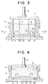
- Figs. 1 - 4 are vertical, sectional views of a molding machine to carry out a first embodiment of the method of the present invention.
- Fig. 5 is a horizontal, sectional view taken along Arrow V-V in Fig. 3.
- Fig. 6 is a horizontal, sectional view similar to Fig. 5, showing an alternative example of a thin-plate body.
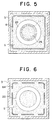
- Fig. 7 is a vertical, sectional view of a molding machine to carry out a second embodiment of the method of the present invention.
- Fig. 8 is a horizontal, sectional view taken along Arrow VIII - VIII in Fig. 7.
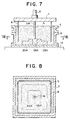
- Fig. 9 is a vertical, sectional view of a molding machine to carry out a third embodiment of the method of the present invention.
- Fig. 10 is a horizontal, sectional view taken along Arrow X- X in Fig. 9.
- a table 1 formed with a central opening 2 is disposed.
- a circular pattern 23 formed with a large, central depression or pocket 26 (Figs. 3 and 5) is mounted on a pattern plate 20.
- the pattern plate 20 is placed on the table 1 such that it bridges the opening 2 of the table 1.
- the pattern plate 20 has a plurality of vent holes 21 provided with vent plugs 22. These vent plugs 22 communicate with the opening 2 of the table 1.
- a flask 3 and a filling frame 4 are placed on the pattern plate 20.
- the pattern plate 20, flask 3, and filling frame 4 define a mold space. Molding sand S is then put into the mold space, and the surface of it is leveled.
- Fig. 2 the mold space is then sealingly covered with a covering member 5, which is connected by way of a valve 5A to a source P for supplying compressed air into the mold space.
- the valve 5A is opened for a while, so that compressed air is introduced into the mold space.
- the introduced air pre-compacts the molding sand S, especially its lower part close to the pattern plate 20, and is then evacuated from the vent plugs 22.
- the covering member 5 is then removed.
- a pre-compressing device or means comprised of a tubular thin-plate body 8 attached to a rigid plate 7, which in turn is attached to a piston rod 6 of a cylinder (not shown), is moved to a position just above the mold space.
- the length of the thin-plate body 8 generally equals the total height of the flask 3 and filling frame 4.
- the diameter of the body 8 is slightly less than that of the mold space.
- the piston rod 6 is lowered so that the thin-plate body 8 is inserted into the molding sand S until the lower end of it reaches a part of the molding sand above the pattern plate 20. By this insertion the lower part of the molding sand near the inner side surface of the flask is well pre-compressed.
- the thin-plate body 8 is then withdrawn from the molding sand S and moved away from the mold space.
- the thin-plate body 8 is preferably 20 mm thick. If it were thicker, a void would be left in the surface of the molding sand S when the thin-plate body 8 is withdrawn from it.
- a press plate 10 attached to a piston rod 9 of a cylinder (not shown) is pressed against the entire surface of the molding sand to thereby compact all the molding sand. This completes the process of producing a mold.
- a thin-plate body 8A that has a plurality of metal strips and angles as in the drawing may be used.
- an additional tubular thin-plate body 11 (shown in dotted lines), which has a diameter slightly less than the inner side surface 25 of the pattern 20, may be attached to the rigid plate 7 such that the lower end of the thin-plate body 11 reaches the lower part of the molding sand S near the inner side surface 25 of the pattern 20 as in Fig. 3 when the piston rod 6 is lowered.
- the thin-plate body 11 well pre-compresses this part of the molding sand.
- Figs. 7 and 8 a second embodiment of the method of the present invention is explained.
- another method is used to pre-compress the lower part of the molding sand near the outer and inner side surfaces of a pattern and to consolidate all the molding sand.
- the same numbers and letters are used for the same elements of the first embodiment, and similar numbers and letters for similar elements.
- a pattern plate 20A (with no vent hole) is placed on a table 1A (with no opening).
- a pattern 23A is mounted on the pattern plate 20A.
- the pattern 23A is in the form of an almost square block and has a small, cylindrical central throughbore or pocket 26A.
- the pattern plate 20A, flask 3, and filling frame define a mold space.
- the device to pre-compact the molding sand includes a piston rod 6, a rigid plate 7 attached to it, and a thin-plate body 8 and a round bar or rod 11A, both attached to the rigid plate 7.
- the diameter of the round rod 11A is slightly less than that of the pocket 26A.
- molding sand is fed into the mold space, and the side surface of the molding sand is leveled.
- the piston rod 6 is then lowered until the thin-plate body 8 and round rod 11A reach the lower part of the molding sand near the outer and inner side surfaces of the pattern 23A, respectively, as in Fig. 7.
- the molding sand is well pre-compressed at the part near the side surfaces by the thin-plate body 8 and rod 11A.
- the device is then moved away from the molding sand.
- a covering member which is connected to means for supplying compressed air through a valve (such as the covering member 5, the valve 5A, and the means P of Fig. 2), is then sealingly attached to the top of the filling frame 4.
- the valve is opened to introduce compressed air into the mold space to consolidate all the molding sand.
- a mold is produced.
- a third embodiment of the method to pre-compress the molding sand is shown. This method is similar to that of the second embodiment.
- a pattern 23B and a thin-plate body 8B are circular in plan, but the inner side surface of the flask 3 is square.
- the distance between the inner side surface of the flask and outer side surface of the pattern is great at the inner corners of the flask 3. Molding sand tends to be not well consolidated at these corners.
- four more thin-plate bodies or angle rods 12 are attached to comers of the rigid plate 7 so that the lower part of the molding sand S near the inner side surface of the flask 3 is well pre-compressed.
- the foregoing embodiments are exemplary only.
- One or more of thin-plate bodies and/or rods may be selectively used depending on the part of the molding sand to be especially compressed and the shape of a pattern and a flask. Any other modification to or variation of the embodiments, or any combination of the embodiments, can be made within the scope of the appended claims.
- the vent holes and vent plugs may be eliminated in the first embodiment.
- pre-compacting by compressed air pre-compacting by the jolting process may be used.
- molding sand is pre-compacted by compressed air before pre-compressing by a thin-plate body, this sequence may be changed.
- the molding sand may be pre-compressed first by the thin-plate body and then be pre-compacted by compressed air.
- the thin-plate body and/or rod is inserted into molding sand in the mold space by lowering it, instead of this, by a conventional method the molding sand in the mold space may be lifted to the fixed thin-plate body and/or rod.
Landscapes
- Engineering & Computer Science (AREA)
- Mechanical Engineering (AREA)
- Casting Devices For Molds (AREA)
Abstract
Description
- This invention relates to a method for producing a mold by pressing molding sand which is first put in a mold space defined by a pattern plate and a flask.
- To produce a mold from molding sand, it must be compacted. However, molding sand tends not to be well compacted at the part near lower peripheral (i.e., lower inner and outer side) surfaces of the mold and the inner side surface of the flask.
- This poor compacting is caused because a force to press the molding sand is not well transmitted to the lower part of it near these side surfaces due to frictional resistance by the side surfaces. A mold having a part or parts that are not dense tends to deform, particularly when it is filled with molten metal. Thus it fails to produce a good cast of accurate dimensions.
- Conventionally, before pressing all the molding sand, pre-compacting it by the jolt process or by circulating compressed air through it has been tried. However, even by this pre-compaction the molding sand is insufficiently consolidated at the part near the inner or outer side surface of the pattern or the inner side surface of the flask. To sufficiently pre-compact molding sand by such methods, heavy and bulky equipment is required. This equipment causes serious vibrations and noises.
- This invention is conceived in view of the above prior-art drawbacks. It aims to provide a method to sufficiently consolidate molding sand to produce a mold wherein the molding sand is also well consolidated at the lower part of it near the inner and outer side surfaces of a pattern and the inner side surface of the flask.
- The method of the present invention includes pre-compressing molding sand in a mold space at the lower part of it near the side surfaces of the pattern and flask, where it tends to be not well consolidated, by inserting a thin-plate body or rod into the molding sand at the lower part near the side surfaces. The method also includes pre-compacting the molding sand at the lower part of it (near the pattern plate) and/or consolidating all the molding sand. Below the details of the invention will be explained through embodiments by reference to the accompanying drawings.
- Figs. 1 - 4 are vertical, sectional views of a molding machine to carry out a first embodiment of the method of the present invention.
- Fig. 5 is a horizontal, sectional view taken along Arrow V-V in Fig. 3.
- Fig. 6 is a horizontal, sectional view similar to Fig. 5, showing an alternative example of a thin-plate body.
- Fig. 7 is a vertical, sectional view of a molding machine to carry out a second embodiment of the method of the present invention.
- Fig. 8 is a horizontal, sectional view taken along Arrow VIII - VIII in Fig. 7.
- Fig. 9 is a vertical, sectional view of a molding machine to carry out a third embodiment of the method of the present invention.
- Fig. 10 is a horizontal, sectional view taken along Arrow X- X in Fig. 9.
- Now the embodiments of the present invention will be explained in detail by reference to the drawings.
- In Figs. 1 - 5 a first embodiment of the method of the present invention is explained. In Fig. 1 a table 1 formed with a
central opening 2 is disposed. Acircular pattern 23 formed with a large, central depression or pocket 26 (Figs. 3 and 5) is mounted on apattern plate 20. Thepattern plate 20 is placed on the table 1 such that it bridges theopening 2 of the table 1. Thepattern plate 20 has a plurality ofvent holes 21 provided withvent plugs 22. Thesevent plugs 22 communicate with theopening 2 of the table 1. Aflask 3 and a fillingframe 4 are placed on thepattern plate 20. Thepattern plate 20,flask 3, and fillingframe 4 define a mold space. Molding sand S is then put into the mold space, and the surface of it is leveled. - In Fig. 2 the mold space is then sealingly covered with a covering
member 5, which is connected by way of a valve 5A to a source P for supplying compressed air into the mold space. The valve 5A is opened for a while, so that compressed air is introduced into the mold space. The introduced air pre-compacts the molding sand S, especially its lower part close to thepattern plate 20, and is then evacuated from thevent plugs 22. Thus the lower part of the molding sand S has a high bulk density. The coveringmember 5 is then removed. - In Fig. 3 a pre-compressing device or means comprised of a tubular thin-
plate body 8 attached to arigid plate 7, which in turn is attached to apiston rod 6 of a cylinder (not shown), is moved to a position just above the mold space. The length of the thin-plate body 8 generally equals the total height of theflask 3 and fillingframe 4. The diameter of thebody 8 is slightly less than that of the mold space. Thepiston rod 6 is lowered so that the thin-plate body 8 is inserted into the molding sand S until the lower end of it reaches a part of the molding sand above thepattern plate 20. By this insertion the lower part of the molding sand near the inner side surface of the flask is well pre-compressed. The thin-plate body 8 is then withdrawn from the molding sand S and moved away from the mold space. The thin-plate body 8 is preferably 20 mm thick. If it were thicker, a void would be left in the surface of the molding sand S when the thin-plate body 8 is withdrawn from it. - In Fig. 4 a
press plate 10 attached to a piston rod 9 of a cylinder (not shown) is pressed against the entire surface of the molding sand to thereby compact all the molding sand. This completes the process of producing a mold. - Referring to Fig. 6, instead of using a single tubular thin-plate body such as the
body 8 shown in Figs. 3 and 5, a thin-plate body 8A that has a plurality of metal strips and angles as in the drawing may be used. - Referring to Figs. 3 and 5, an additional tubular thin-plate body 11 (shown in dotted lines), which has a diameter slightly less than the
inner side surface 25 of thepattern 20, may be attached to therigid plate 7 such that the lower end of the thin-plate body 11 reaches the lower part of the molding sand S near theinner side surface 25 of thepattern 20 as in Fig. 3 when thepiston rod 6 is lowered. The thin-plate body 11 well pre-compresses this part of the molding sand. - In Figs. 7 and 8 a second embodiment of the method of the present invention is explained. In this embodiment another method is used to pre-compress the lower part of the molding sand near the outer and inner side surfaces of a pattern and to consolidate all the molding sand. The same numbers and letters are used for the same elements of the first embodiment, and similar numbers and letters for similar elements.
- As in Figs. 7 and 8, a
pattern plate 20A (with no vent hole) is placed on a table 1A (with no opening). Apattern 23A is mounted on thepattern plate 20A. Thepattern 23A is in the form of an almost square block and has a small, cylindrical central throughbore orpocket 26A. Thepattern plate 20A,flask 3, and filling frame define a mold space. The device to pre-compact the molding sand includes apiston rod 6, arigid plate 7 attached to it, and a thin-plate body 8 and a round bar or rod 11A, both attached to therigid plate 7. The diameter of the round rod 11A is slightly less than that of thepocket 26A. - In operation, first, molding sand is fed into the mold space, and the side surface of the molding sand is leveled. The
piston rod 6 is then lowered until the thin-plate body 8 and round rod 11A reach the lower part of the molding sand near the outer and inner side surfaces of thepattern 23A, respectively, as in Fig. 7. The molding sand is well pre-compressed at the part near the side surfaces by the thin-plate body 8 and rod 11A. After pre-compressing, the device is then moved away from the molding sand. A covering member, which is connected to means for supplying compressed air through a valve (such as the coveringmember 5, the valve 5A, and the means P of Fig. 2), is then sealingly attached to the top of the fillingframe 4. The valve is opened to introduce compressed air into the mold space to consolidate all the molding sand. Thus a mold is produced. - In Figs. 9 and 10 a third embodiment of the method to pre-compress the molding sand is shown. This method is similar to that of the second embodiment. In this third embodiment a
pattern 23B and a thin-plate body 8B are circular in plan, but the inner side surface of theflask 3 is square. Thus the distance between the inner side surface of the flask and outer side surface of the pattern is great at the inner corners of theflask 3. Molding sand tends to be not well consolidated at these corners. Thus in this embodiment four more thin-plate bodies orangle rods 12 are attached to comers of therigid plate 7 so that the lower part of the molding sand S near the inner side surface of theflask 3 is well pre-compressed. When the central rod 11A, thin-plate body 8B, andangle rods 12, are inserted into the molding sand, it is well pre-compressed at the lower part near the inner and outer side surface of thepattern 23B and the inner side surface of theflask 3. After the molding is pre-compressed, compressed air is applied to the entire surface of it as in the second embodiment. Thus a mold is produced. If desired, allangle rods 12 may be wider than those shown in Fig. 10. - The foregoing embodiments are exemplary only. One or more of thin-plate bodies and/or rods may be selectively used depending on the part of the molding sand to be especially compressed and the shape of a pattern and a flask. Any other modification to or variation of the embodiments, or any combination of the embodiments, can be made within the scope of the appended claims. For example, the vent holes and vent plugs may be eliminated in the first embodiment. Further, in the first embodiment, instead of pre-compacting by compressed air, pre-compacting by the jolting process may be used. Although in the first embodiment molding sand is pre-compacted by compressed air before pre-compressing by a thin-plate body, this sequence may be changed. That is, the molding sand may be pre-compressed first by the thin-plate body and then be pre-compacted by compressed air. Further, although in the foregoing embodiments the thin-plate body and/or rod is inserted into molding sand in the mold space by lowering it, instead of this, by a conventional method the molding sand in the mold space may be lifted to the fixed thin-plate body and/or rod.
Claims (5)
- A method for producing a mold by compressing molding sand, comprising the steps of:introducing molding sand in a mold space defined by a pattern plate, which has a pattern, and a flask;pre-compacting the introduced molding sand at a part thereof near the pattern plate;moving the pattern plate and a means for pre-compressing the molding sand relatively close to each other, said means being disposed above the mold space, said means including at least one thin-plate body or rod that is laterally spaced apart from the inner side surface of the flask inwardly, and/or that is laterally spaced apart from the inner and outer side surfaces of the pattern, so as to insert said at least one thin-plate or rod into the molding sand, thereby pre-compressing the molding sand at the part thereof that is near the pattern plate, and that is near at least one of the inner side surface of the flask and the inner and outer side surfaces of the pattern;moving the pattern plate and said means relatively away from each other so as to withdraw said at least one thin-plate body or rod from the molding sand; andafter the withdrawal, pressing the entire surface of the molding sand.
- A method for producing a mold by compressing molding sand, comprising the steps of:introducing molding sand in a mold space defined by a pattern plate, which has a pattern, and a flask;moving the pattern plate and a means for pre-compressing the molding sand relatively close to each other, said means being disposed above the mold space, said means including at least one thin-plate body or rod that is laterally spaced apart from the inner side surface of the flask inwardly, and/or that is laterally spaced apart from the inner and outer side surfaces of the pattern, so as to insert said at least one thin-plate or rod into the molding sand, thereby pre-compressing the molding sand at the part thereof that is near the pattern plate, and that is near at least one of the inner side surface of the flask and the inner and outer side surfaces of the pattern;moving the pattern plate and said means relatively away from each other so as to withdraw said at least one thin-plate body or rod from the molding sand;after the withdrawal, pre-compacting the molding sand at a part thereof near the pattern plate; andpressing the entire surface of the molding sand.
- The method of claim 1 or 2, wherein said step of pre-compacting includes applying compressed air to the molding sand in the mold space.
- The method of claim 1 or 2, wherein said step of pre-compacting includes pre-compacting by the jolting process.
- A method for producing a mold by compressing a molding sand, comprising the steps of:introducing molding sand in a mold space defined by a pattern plate, which has a pattern, and a flask;moving the pattern plate and a means for pre-compressing the molding sand relatively close to each other, said means being disposed above the mold space, said means including at least one thin-plate body or rod that is laterally spaced apart from the inner side surface of the flask inwardly, and/or that is laterally spaced apart from the inner and outer side surfaces of the pattern, so as to insert said at least one thin-plate or rod into the molding sand, thereby pre-compressing the molding sand at the part thereof that is near the pattern plate, and that is near at least one of the inner side surface of the flask and the inner and outer side surfaces of the pattern;moving the pattern plate and said means relatively away from each other so as to withdraw said at least one thin-plate body or rod from the molding sand; andapplying compressed air to the surface of the molding sand to thereby compress all the molding sand.
Applications Claiming Priority (6)
| Application Number | Priority Date | Filing Date | Title |
|---|---|---|---|
| JP12906196 | 1996-04-24 | ||
| JP129061/96 | 1996-04-24 | ||
| JP12906196A JP3266506B2 (en) | 1996-04-24 | 1996-04-24 | Mold making method |
| JP140772/96 | 1996-05-10 | ||
| JP14077296A JP3271740B2 (en) | 1996-05-10 | 1996-05-10 | Mold making method |
| JP14077296 | 1996-05-10 |
Publications (2)
| Publication Number | Publication Date |
|---|---|
| EP0803303A1 true EP0803303A1 (en) | 1997-10-29 |
| EP0803303B1 EP0803303B1 (en) | 1999-09-01 |
Family
ID=26464579
Family Applications (1)
| Application Number | Title | Priority Date | Filing Date |
|---|---|---|---|
| EP97106203A Expired - Lifetime EP0803303B1 (en) | 1996-04-24 | 1997-04-15 | Method for producing a mold |
Country Status (7)
| Country | Link |
|---|---|
| EP (1) | EP0803303B1 (en) |
| KR (1) | KR970073798A (en) |
| CN (1) | CN1071163C (en) |
| DE (1) | DE69700459T2 (en) |
| ES (1) | ES2138411T3 (en) |
| ID (1) | ID16815A (en) |
| SG (1) | SG52957A1 (en) |
Cited By (2)
| Publication number | Priority date | Publication date | Assignee | Title |
|---|---|---|---|---|
| EP0867242A1 (en) * | 1997-03-28 | 1998-09-30 | Sintokogio, Ltd. | Method and apparatus for pre-compacting molding sand |
| EP0900606A1 (en) * | 1997-09-05 | 1999-03-10 | Sintokogio, Ltd. | Apparatus for making mold |
Families Citing this family (5)
| Publication number | Priority date | Publication date | Assignee | Title |
|---|---|---|---|---|
| GB0611430D0 (en) * | 2006-06-09 | 2006-07-19 | Foseco Int | Improved feeder element for metal casting |
| DE102011051420B4 (en) | 2011-06-28 | 2015-09-24 | Künkel Wagner Germany Gmbh | Forming box-bound sand molds and sand molds |
| CN104759595B (en) * | 2015-03-31 | 2016-10-19 | 青岛意特机械有限公司 | Microseism squeeze molding machine and formative method thereof |
| CN107262674A (en) * | 2017-07-04 | 2017-10-20 | 湖南江滨机器(集团)有限责任公司 | A kind of salt core pressing mold and salt core, manufacturing method |
| CN108339951B (en) * | 2018-05-03 | 2024-07-26 | 临沂市卓杰机械有限公司 | Casting large-end cavity molding assembly, automatic molding machine and molding process |
Citations (4)
| Publication number | Priority date | Publication date | Assignee | Title |
|---|---|---|---|---|
| EP0299941A2 (en) * | 1987-07-15 | 1989-01-18 | Hybe Maskin System AB | An apparatus for under compaction or ramming in a moulding machine |
| JPH0428453A (en) * | 1990-05-18 | 1992-01-31 | Sintokogio Ltd | Method for molding mold and pressurizing compressing apparatus |
| EP0490701A2 (en) * | 1990-12-14 | 1992-06-17 | Sintokogio Ltd. | Compressed air blowing apparatus for use in green sand mold molding facility |
| EP0748663A1 (en) * | 1995-06-16 | 1996-12-18 | Sintokogio, Ltd. | Apparatus and method for producing molds |
-
1997
- 1997-04-15 EP EP97106203A patent/EP0803303B1/en not_active Expired - Lifetime
- 1997-04-15 DE DE69700459T patent/DE69700459T2/en not_active Expired - Fee Related
- 1997-04-15 ES ES97106203T patent/ES2138411T3/en not_active Expired - Lifetime
- 1997-04-19 SG SG1997001259A patent/SG52957A1/en unknown
- 1997-04-22 CN CN97110781A patent/CN1071163C/en not_active Expired - Fee Related
- 1997-04-22 ID IDP971335A patent/ID16815A/en unknown
- 1997-04-24 KR KR1019970015243A patent/KR970073798A/en not_active Application Discontinuation
Patent Citations (4)
| Publication number | Priority date | Publication date | Assignee | Title |
|---|---|---|---|---|
| EP0299941A2 (en) * | 1987-07-15 | 1989-01-18 | Hybe Maskin System AB | An apparatus for under compaction or ramming in a moulding machine |
| JPH0428453A (en) * | 1990-05-18 | 1992-01-31 | Sintokogio Ltd | Method for molding mold and pressurizing compressing apparatus |
| EP0490701A2 (en) * | 1990-12-14 | 1992-06-17 | Sintokogio Ltd. | Compressed air blowing apparatus for use in green sand mold molding facility |
| EP0748663A1 (en) * | 1995-06-16 | 1996-12-18 | Sintokogio, Ltd. | Apparatus and method for producing molds |
Non-Patent Citations (1)
| Title |
|---|
| PATENT ABSTRACTS OF JAPAN vol. 016, no. 195 (M - 1246) 12 May 1992 (1992-05-12) * |
Cited By (3)
| Publication number | Priority date | Publication date | Assignee | Title |
|---|---|---|---|---|
| EP0867242A1 (en) * | 1997-03-28 | 1998-09-30 | Sintokogio, Ltd. | Method and apparatus for pre-compacting molding sand |
| EP0900606A1 (en) * | 1997-09-05 | 1999-03-10 | Sintokogio, Ltd. | Apparatus for making mold |
| US5996678A (en) * | 1997-09-05 | 1999-12-07 | Sintokogio, Ltd. | Apparatus for making mold |
Also Published As
| Publication number | Publication date |
|---|---|
| ES2138411T3 (en) | 2000-01-01 |
| CN1170646A (en) | 1998-01-21 |
| KR970073798A (en) | 1997-12-10 |
| DE69700459T2 (en) | 2000-03-16 |
| CN1071163C (en) | 2001-09-19 |
| SG52957A1 (en) | 1998-09-28 |
| DE69700459D1 (en) | 1999-10-07 |
| EP0803303B1 (en) | 1999-09-01 |
| ID16815A (en) | 1997-11-13 |
Similar Documents
| Publication | Publication Date | Title |
|---|---|---|
| EP0803303B1 (en) | Method for producing a mold | |
| EP0748663B1 (en) | Apparatus and method for producing molds | |
| GB2043507A (en) | Moulding apparatus | |
| US20060008376A1 (en) | Method and an apparatus for producing multi-level components by shock compression of powdered material | |
| EP0465930A2 (en) | Method and apparatus for compacting foundry molding materials | |
| JP2759433B2 (en) | Method for squeezing a mold from powder material in two directions in a mold train | |
| JP3329691B2 (en) | Sand molding method and apparatus | |
| CA1201272A (en) | Apparatus and method for breaking sand free from a pattern pocket in a mold | |
| EP0867242A1 (en) | Method and apparatus for pre-compacting molding sand | |
| US5137091A (en) | Process of producing molded body from green molding sand | |
| RU2172656C2 (en) | Casting mold manufacture method and apparatus | |
| JPS638728Y2 (en) | ||
| JPH091288A (en) | Molding method and molding machine | |
| JPS6239079Y2 (en) | ||
| US5601777A (en) | Process for compressing granular material in a molding box | |
| CA1220014A (en) | Method and apparatus for making foundry molds | |
| JPH0428453A (en) | Method for molding mold and pressurizing compressing apparatus | |
| JPS6239081Y2 (en) | ||
| JPH0910892A (en) | Mold molding method | |
| JPH0367780B2 (en) | ||
| JP3262201B2 (en) | Mold making method | |
| JPH07150202A (en) | Feeder of powder molding press | |
| JPH03146243A (en) | Apparatus for molding casting mold | |
| RU2024354C1 (en) | Method for molding of long articles | |
| JPH0233955Y2 (en) |
Legal Events
| Date | Code | Title | Description |
|---|---|---|---|
| PUAI | Public reference made under article 153(3) epc to a published international application that has entered the european phase |
Free format text: ORIGINAL CODE: 0009012 |
|
| AK | Designated contracting states |
Kind code of ref document: A1 Designated state(s): DE ES FR GB IT |
|
| 17P | Request for examination filed |
Effective date: 19980109 |
|
| 17Q | First examination report despatched |
Effective date: 19980224 |
|
| GRAG | Despatch of communication of intention to grant |
Free format text: ORIGINAL CODE: EPIDOS AGRA |
|
| GRAG | Despatch of communication of intention to grant |
Free format text: ORIGINAL CODE: EPIDOS AGRA |
|
| GRAH | Despatch of communication of intention to grant a patent |
Free format text: ORIGINAL CODE: EPIDOS IGRA |
|
| GRAH | Despatch of communication of intention to grant a patent |
Free format text: ORIGINAL CODE: EPIDOS IGRA |
|
| GRAA | (expected) grant |
Free format text: ORIGINAL CODE: 0009210 |
|
| AK | Designated contracting states |
Kind code of ref document: B1 Designated state(s): DE ES FR GB IT |
|
| REF | Corresponds to: |
Ref document number: 69700459 Country of ref document: DE Date of ref document: 19991007 |
|
| ET | Fr: translation filed | ||
| ITF | It: translation for a ep patent filed | ||
| REG | Reference to a national code |
Ref country code: ES Ref legal event code: FG2A Ref document number: 2138411 Country of ref document: ES Kind code of ref document: T3 |
|
| PLBE | No opposition filed within time limit |
Free format text: ORIGINAL CODE: 0009261 |
|
| STAA | Information on the status of an ep patent application or granted ep patent |
Free format text: STATUS: NO OPPOSITION FILED WITHIN TIME LIMIT |
|
| 26N | No opposition filed | ||
| PGFP | Annual fee paid to national office [announced via postgrant information from national office to epo] |
Ref country code: GB Payment date: 20010330 Year of fee payment: 5 Ref country code: FR Payment date: 20010330 Year of fee payment: 5 |
|
| PGFP | Annual fee paid to national office [announced via postgrant information from national office to epo] |
Ref country code: DE Payment date: 20010423 Year of fee payment: 5 |
|
| PGFP | Annual fee paid to national office [announced via postgrant information from national office to epo] |
Ref country code: ES Payment date: 20010514 Year of fee payment: 5 |
|
| REG | Reference to a national code |
Ref country code: GB Ref legal event code: IF02 |
|
| PG25 | Lapsed in a contracting state [announced via postgrant information from national office to epo] |
Ref country code: GB Free format text: LAPSE BECAUSE OF NON-PAYMENT OF DUE FEES Effective date: 20020415 |
|
| PG25 | Lapsed in a contracting state [announced via postgrant information from national office to epo] |
Ref country code: ES Free format text: LAPSE BECAUSE OF NON-PAYMENT OF DUE FEES Effective date: 20020416 |
|
| PG25 | Lapsed in a contracting state [announced via postgrant information from national office to epo] |
Ref country code: DE Free format text: LAPSE BECAUSE OF NON-PAYMENT OF DUE FEES Effective date: 20021101 |
|
| GBPC | Gb: european patent ceased through non-payment of renewal fee |
Effective date: 20020415 |
|
| PG25 | Lapsed in a contracting state [announced via postgrant information from national office to epo] |
Ref country code: FR Free format text: LAPSE BECAUSE OF NON-PAYMENT OF DUE FEES Effective date: 20021231 |
|
| REG | Reference to a national code |
Ref country code: FR Ref legal event code: ST |
|
| REG | Reference to a national code |
Ref country code: ES Ref legal event code: FD2A Effective date: 20030514 |
|
| PG25 | Lapsed in a contracting state [announced via postgrant information from national office to epo] |
Ref country code: IT Free format text: LAPSE BECAUSE OF NON-PAYMENT OF DUE FEES;WARNING: LAPSES OF ITALIAN PATENTS WITH EFFECTIVE DATE BEFORE 2007 MAY HAVE OCCURRED AT ANY TIME BEFORE 2007. THE CORRECT EFFECTIVE DATE MAY BE DIFFERENT FROM THE ONE RECORDED. Effective date: 20050415 |