EP0803163B1 - Systeme multiplexeur mettant en uvre des codeurs a debit binaire constant - Google Patents
Systeme multiplexeur mettant en uvre des codeurs a debit binaire constant Download PDFInfo
- Publication number
- EP0803163B1 EP0803163B1 EP94916545A EP94916545A EP0803163B1 EP 0803163 B1 EP0803163 B1 EP 0803163B1 EP 94916545 A EP94916545 A EP 94916545A EP 94916545 A EP94916545 A EP 94916545A EP 0803163 B1 EP0803163 B1 EP 0803163B1
- Authority
- EP
- European Patent Office
- Prior art keywords
- bit rate
- signal
- complexity
- data
- input terminal
- Prior art date
- Legal status (The legal status is an assumption and is not a legal conclusion. Google has not performed a legal analysis and makes no representation as to the accuracy of the status listed.)
- Expired - Lifetime
Links
Images


Classifications
-
- H—ELECTRICITY
- H04—ELECTRIC COMMUNICATION TECHNIQUE
- H04N—PICTORIAL COMMUNICATION, e.g. TELEVISION
- H04N7/00—Television systems
- H04N7/12—Systems in which the television signal is transmitted via one channel or a plurality of parallel channels, the bandwidth of each channel being less than the bandwidth of the television signal
-
- H—ELECTRICITY
- H04—ELECTRIC COMMUNICATION TECHNIQUE
- H04N—PICTORIAL COMMUNICATION, e.g. TELEVISION
- H04N21/00—Selective content distribution, e.g. interactive television or video on demand [VOD]
- H04N21/20—Servers specifically adapted for the distribution of content, e.g. VOD servers; Operations thereof
- H04N21/23—Processing of content or additional data; Elementary server operations; Server middleware
- H04N21/236—Assembling of a multiplex stream, e.g. transport stream, by combining a video stream with other content or additional data, e.g. inserting a URL [Uniform Resource Locator] into a video stream, multiplexing software data into a video stream; Remultiplexing of multiplex streams; Insertion of stuffing bits into the multiplex stream, e.g. to obtain a constant bit-rate; Assembling of a packetised elementary stream
- H04N21/2365—Multiplexing of several video streams
-
- H—ELECTRICITY
- H04—ELECTRIC COMMUNICATION TECHNIQUE
- H04J—MULTIPLEX COMMUNICATION
- H04J3/00—Time-division multiplex systems
- H04J3/16—Time-division multiplex systems in which the time allocation to individual channels within a transmission cycle is variable, e.g. to accommodate varying complexity of signals, to vary number of channels transmitted
- H04J3/1682—Allocation of channels according to the instantaneous demands of the users, e.g. concentrated multiplexers, statistical multiplexers
- H04J3/1688—Allocation of channels according to the instantaneous demands of the users, e.g. concentrated multiplexers, statistical multiplexers the demands of the users being taken into account after redundancy removal, e.g. by predictive coding, by variable sampling
-
- H—ELECTRICITY
- H04—ELECTRIC COMMUNICATION TECHNIQUE
- H04N—PICTORIAL COMMUNICATION, e.g. TELEVISION
- H04N19/00—Methods or arrangements for coding, decoding, compressing or decompressing digital video signals
- H04N19/10—Methods or arrangements for coding, decoding, compressing or decompressing digital video signals using adaptive coding
- H04N19/102—Methods or arrangements for coding, decoding, compressing or decompressing digital video signals using adaptive coding characterised by the element, parameter or selection affected or controlled by the adaptive coding
- H04N19/115—Selection of the code volume for a coding unit prior to coding
-
- H—ELECTRICITY
- H04—ELECTRIC COMMUNICATION TECHNIQUE
- H04N—PICTORIAL COMMUNICATION, e.g. TELEVISION
- H04N19/00—Methods or arrangements for coding, decoding, compressing or decompressing digital video signals
- H04N19/10—Methods or arrangements for coding, decoding, compressing or decompressing digital video signals using adaptive coding
- H04N19/102—Methods or arrangements for coding, decoding, compressing or decompressing digital video signals using adaptive coding characterised by the element, parameter or selection affected or controlled by the adaptive coding
- H04N19/124—Quantisation
-
- H—ELECTRICITY
- H04—ELECTRIC COMMUNICATION TECHNIQUE
- H04N—PICTORIAL COMMUNICATION, e.g. TELEVISION
- H04N19/00—Methods or arrangements for coding, decoding, compressing or decompressing digital video signals
- H04N19/10—Methods or arrangements for coding, decoding, compressing or decompressing digital video signals using adaptive coding
- H04N19/134—Methods or arrangements for coding, decoding, compressing or decompressing digital video signals using adaptive coding characterised by the element, parameter or criterion affecting or controlling the adaptive coding
- H04N19/136—Incoming video signal characteristics or properties
- H04N19/14—Coding unit complexity, e.g. amount of activity or edge presence estimation
-
- H—ELECTRICITY
- H04—ELECTRIC COMMUNICATION TECHNIQUE
- H04N—PICTORIAL COMMUNICATION, e.g. TELEVISION
- H04N19/00—Methods or arrangements for coding, decoding, compressing or decompressing digital video signals
- H04N19/10—Methods or arrangements for coding, decoding, compressing or decompressing digital video signals using adaptive coding
- H04N19/169—Methods or arrangements for coding, decoding, compressing or decompressing digital video signals using adaptive coding characterised by the coding unit, i.e. the structural portion or semantic portion of the video signal being the object or the subject of the adaptive coding
- H04N19/17—Methods or arrangements for coding, decoding, compressing or decompressing digital video signals using adaptive coding characterised by the coding unit, i.e. the structural portion or semantic portion of the video signal being the object or the subject of the adaptive coding the unit being an image region, e.g. an object
- H04N19/172—Methods or arrangements for coding, decoding, compressing or decompressing digital video signals using adaptive coding characterised by the coding unit, i.e. the structural portion or semantic portion of the video signal being the object or the subject of the adaptive coding the unit being an image region, e.g. an object the region being a picture, frame or field
-
- H—ELECTRICITY
- H04—ELECTRIC COMMUNICATION TECHNIQUE
- H04N—PICTORIAL COMMUNICATION, e.g. TELEVISION
- H04N19/00—Methods or arrangements for coding, decoding, compressing or decompressing digital video signals
- H04N19/10—Methods or arrangements for coding, decoding, compressing or decompressing digital video signals using adaptive coding
- H04N19/169—Methods or arrangements for coding, decoding, compressing or decompressing digital video signals using adaptive coding characterised by the coding unit, i.e. the structural portion or semantic portion of the video signal being the object or the subject of the adaptive coding
- H04N19/17—Methods or arrangements for coding, decoding, compressing or decompressing digital video signals using adaptive coding characterised by the coding unit, i.e. the structural portion or semantic portion of the video signal being the object or the subject of the adaptive coding the unit being an image region, e.g. an object
- H04N19/176—Methods or arrangements for coding, decoding, compressing or decompressing digital video signals using adaptive coding characterised by the coding unit, i.e. the structural portion or semantic portion of the video signal being the object or the subject of the adaptive coding the unit being an image region, e.g. an object the region being a block, e.g. a macroblock
-
- H—ELECTRICITY
- H04—ELECTRIC COMMUNICATION TECHNIQUE
- H04N—PICTORIAL COMMUNICATION, e.g. TELEVISION
- H04N19/00—Methods or arrangements for coding, decoding, compressing or decompressing digital video signals
- H04N19/10—Methods or arrangements for coding, decoding, compressing or decompressing digital video signals using adaptive coding
- H04N19/169—Methods or arrangements for coding, decoding, compressing or decompressing digital video signals using adaptive coding characterised by the coding unit, i.e. the structural portion or semantic portion of the video signal being the object or the subject of the adaptive coding
- H04N19/177—Methods or arrangements for coding, decoding, compressing or decompressing digital video signals using adaptive coding characterised by the coding unit, i.e. the structural portion or semantic portion of the video signal being the object or the subject of the adaptive coding the unit being a group of pictures [GOP]
-
- H—ELECTRICITY
- H04—ELECTRIC COMMUNICATION TECHNIQUE
- H04N—PICTORIAL COMMUNICATION, e.g. TELEVISION
- H04N19/00—Methods or arrangements for coding, decoding, compressing or decompressing digital video signals
- H04N19/60—Methods or arrangements for coding, decoding, compressing or decompressing digital video signals using transform coding
- H04N19/61—Methods or arrangements for coding, decoding, compressing or decompressing digital video signals using transform coding in combination with predictive coding
-
- H—ELECTRICITY
- H04—ELECTRIC COMMUNICATION TECHNIQUE
- H04N—PICTORIAL COMMUNICATION, e.g. TELEVISION
- H04N21/00—Selective content distribution, e.g. interactive television or video on demand [VOD]
- H04N21/20—Servers specifically adapted for the distribution of content, e.g. VOD servers; Operations thereof
- H04N21/23—Processing of content or additional data; Elementary server operations; Server middleware
- H04N21/236—Assembling of a multiplex stream, e.g. transport stream, by combining a video stream with other content or additional data, e.g. inserting a URL [Uniform Resource Locator] into a video stream, multiplexing software data into a video stream; Remultiplexing of multiplex streams; Insertion of stuffing bits into the multiplex stream, e.g. to obtain a constant bit-rate; Assembling of a packetised elementary stream
- H04N21/2365—Multiplexing of several video streams
- H04N21/23655—Statistical multiplexing, e.g. by controlling the encoder to alter its bitrate to optimize the bandwidth utilization
-
- H—ELECTRICITY
- H04—ELECTRIC COMMUNICATION TECHNIQUE
- H04N—PICTORIAL COMMUNICATION, e.g. TELEVISION
- H04N19/00—Methods or arrangements for coding, decoding, compressing or decompressing digital video signals
- H04N19/10—Methods or arrangements for coding, decoding, compressing or decompressing digital video signals using adaptive coding
- H04N19/134—Methods or arrangements for coding, decoding, compressing or decompressing digital video signals using adaptive coding characterised by the element, parameter or criterion affecting or controlling the adaptive coding
- H04N19/146—Data rate or code amount at the encoder output
- H04N19/152—Data rate or code amount at the encoder output by measuring the fullness of the transmission buffer
Definitions
- the present application relates to a multiplexer system for dynamically allocating bits in a multiplexed stream of data to respective constant bit rate encoded data channels.
- data from the channels is often combined, or multiplexed, at a head end station into a single data stream.
- the multiplexed data stream is then transmitted over a transmission link, such as a wire, fiber optic or radio link, to a back end station, where the channels of data from the multiplexed data stream are then separated, or demultiplexed, and supplied to the intended recipients.
- a plurality of video signals from respective sources may be transmitted over a satellite link for broadcast to respective television receivers in consumers' homes.
- An exemplary satellite link includes a digital transmission path capable of transmitting 24 megabits per second (Mbps).
- Mbps megabits per second
- VBR encoders variable bit rate encoders
- a VBR encoder produces successive frames of digitally encoded video which have different numbers of bits, depending upon the spatial and temporal complexity of the image represented by the video signal. More spatially complex scenes and/or scenes with motion require more bits to encode them than spatially simple scenes with little motion.
- the average combined bit rate from all the VBR encoders will be less than the maximum bit rate of the transmission link, even though at any given time a single channel encoder may provide a large number of bits in a burst for transmission. For this reason, such apparatus is termed a statistical multiplexer.
- a statistical multiplexer there is a finite probability that the instantaneous combined bit rate from all the channels will exceed the maximum bit rate of the transmission link, resulting in loss of data at the back end station.
- buffers are added for either the respective channels or the multiplexed data stream. However, there still exists a finite probability that those buffers will overflow, again resulting in loss of data at the back end station.
- CBR encoders For each channel, the video signal from each channel is supplied to a CBR encoder.
- a CBR encoder produces a digitally encoded bit stream, representing the video signal supplied to it, at a predetermined constant bit rate.
- a CBR encoder continually modifies the number of quantizing levels into which the video signal is encoded. Using fewer quantizing levels requires fewer bits to represent those levels, and the overall number of bits required to represent the video signal is reduced. Conversely, using more quantizing levels requires more bits to represent those levels, and the overall number of bits required to represent the image is increased.
- the appropriate number of quantizing levels depends upon the complexity of the frame currently being encoded.
- a CBR encoder encodes an image having lower spatial and temporal complexity with an increased number of quantizing levels to produce the predetermined bit rate. Conversely, to encode an image having higher spatial and/or temporal complexity in the allocated number of bits, the number of quantizing levels is reduced.
- CBR encoders produce a constant bit rate, however, controlling the multiplexing of video signals from a plurality of such encoders is simplified.
- Each encoder is a priori allocated a bit rate representing its quota of the total available bit rate of the transmission link.
- One known allocation method allocates equal portions of the total bit rate of the transmission link to each encoder.
- video signals representing different program types inherently have differing complexities. For example, a video channel transmitting a basketball game has a much higher complexity than one transmitting a panel discussion. Thus, the quality of the image reproduced from the encoded video signal representing the basketball game will be lower (probably substantially lower) than that of the panel discussion.
- Another known allocation method which attempts to solve this problem, allocates different bit rates to each CBR encoder based on the expected image complexity of the signal to be encoded.
- the channel transmitting a basketball game would be allocated a larger proportion of the total bit rate of the transmission link than the channel transmitting the panel discussion.
- Such an allocation method can result in the quality of the images reproduced from the encoded signals representing both the basketball game and the panel discussion being more nearly equal.
- Yet another known allocation method allocates the proportion of the total bit rate of the transmission link to channels based on payment by the provider of the signal. The more the provider pays for the transmission of the channel, the greater the proportion of the total bit rate of the transmission link allocated to that channel, and the better the quality of the image reproduced from the encoded signal through that channel.
- Patent US-A-5115309 discloses a method and system for allocating bit rates for a group of parallel encoders, in accordance with the complexity of the data being processed by such encoders.
- the complexity of data, from an image is determined by calculating the average quantization step size (for the parallel encoders) and the average number of bits per pixel employed by each video encoder for the image contained in the previous frame. This technique is however unable to accurately accommodate more than one frame of video data at a time.
- VBR variable bit rate
- RC-VBR joint rate controlled VBR mode
- Bit rate allocation is carried out for each multiplexing epoch (one-sixth of a frame period) according to a signal representative of the complexity of each source.
- a news broadcast contains scenes of very low complexity, (e.g. a news reader sitting behind a desk reading news) interspersed with scenes of very high complexity (e.g. a video clip of a basketball game). If such a video channel were a priori allocated a high proportion of the total bit rate of the transmission link, then the basketball game scene would be reproduced with acceptable quality, but the news reader scene would be encoded with too high a quality, or, in other words, with more bits than is necessary.
- each video source on the average, may be characterized in the same manner as the above news broadcast. I.e. almost every video signal of commercial interest contains scenes of high complexity interspersed with scenes of low complexity. They also realized that the scenes of differing complexity are uncorrelated in time. Furthermore, they have found that, within any given frame period, the images of the different channels have differing complexities, and that these complexity variations are also uncorrelated in time.
- bit rates be dynamically allocated to different channels based on the current image complexity of those channels.
- the complexity of the images currently being transmitted for all the channels are evaluated, and a proportion of the total bit rate of the transmission link is allocated to each channel corresponding in some manner to the relationship of the complexity of the current image of that channel to the overall complexity of the images of all the channels.
- a multiplexer system according to claim 1 is defined.
- a multiplexer system operated in this manner allocates bits to the various channels such that, during any time period, the quality of the reproduced images of all the channels have about the same quality. It further optimizes the overall reproduced image quality.
- a channel transmitting a high complexity image for a period of time will dynamically be allocated a higher bit rate during that period of time, but when the complexity of the image becomes lower, the bit rate allocated to that channel will be reduced, and assigned to other channels which are transmitting higher complexity images.
- Fig. 1 is a block diagram of a multiplexer system incorporating the present invention.
- all signal paths are illustrated as single signal lines.
- the illustrated signal paths could carry multibit digital signals, either in parallel, in which case the signal paths would be composed of multiple signal lines, or serially, in which case the signal paths could be a single data line and/or include a data and clock signal line.
- Other control and clock signal paths not germane to the understanding of the present invention have been omitted from the figure to simplify it.
- a plurality of input terminals 5 are coupled to sources (not shown) of video signals (CHANNEL 1 - CHANNEL K) which are to be transmitted together over a data link.
- the plurality of input terminals 5 are coupled to respective data input terminals of a corresponding plurality of channel processors 10.
- Respective data output terminals of the plurality of channel processors 10 are coupled to corresponding data input terminals 1 - K of a multiplexer (MUX) 20.
- a data output terminal of multiplexer 20 is coupled to an output terminal 15 of the multiplexer system.
- Output terminal 15 is coupled to utilization circuitry (not shown) for transmitting the multiplexed data stream (MUX'ED DATA) over the transmission link.
- Each of the plurality of channel processors 10 further includes a complexity output terminal and a control input terminal.
- the respective complexity output terminals of each of the plurality of channel processors are coupled to corresponding complexity input terminals of a bit rate allocator 30, and respective quota output terminals of the bit rate allocator 30 are coupled to the corresponding control input terminals of the plurality of channel processors 10.
- each channel processor receives a signal at its control input terminal representing the bit rate allocated to it for the next quota period.
- the channel processor then encodes the signal at its data input terminal for the next quota period into a digitally encoded signal at the allocated bit rate.
- the encoded data signal is supplied to the corresponding input terminal of multiplexer 20.
- Multiplexer 20 operates in a known manner to combine the signals from all the channel processors into a multiplexed data stream.
- the multiplexed data stream is then supplied to the circuitry comprising the data link for transmission, also in a known manner.
- the channel processor 10 During the encoding process, the channel processor 10 generates a signal at its complexity output terminal representing the coding complexity of the signal being encoded.
- the bit rate allocator 30 receives the signals from the complexity output terminals of the channel processors 10, and, based on all of the complexity signals, dynamically adjusts the bit rate quotas for the next quota period among the plurality of channel processors 10. In a preferred embodiment, more complex signals are dynamically allocated a relatively higher bit rate than less complex signals. Different methods of determining the complexity of the video signal and for allocating bit rates based on the complexities are described below.
- Fig. 2 is a block diagram of a channel processor which may be used in the multiplexer system illustrated in Fig. 1 .
- a data input terminal 5 is coupled a video signal source (not shown).
- Data input terminal 5 is coupled to a data input terminal of a constant bit rate encoder (CBR) 14, and a complexity analyzer 16.
- a data output terminal of the CBR encoder 14 is coupled to an input terminal of multiplexer (MUX) 20 (of Fig. 1 ).
- a control input terminal (CONTROL) of the channel processor 10 is coupled to a quota input terminal Q of the CBR encoder 10.
- An output terminal of the complexity analyzer 16 is coupled to the complexity output terminal (COMPLEXITY) of the channel processor 10.
- the complexity analyzer 16 analyzes the complexity of the video signal at the data input terminal 5.
- a signal is produced at the output terminal of the complexity analyzer 16 representative of the complexity of the input signal.
- the complexity representative signal is supplied to the bit rate allocator 30 (of Fig. 1 ).
- bit rate allocator 30 provides a signal to the control input terminal (CONTROL) of this channel processor 10 (and the other channel processors 10) representing the bit rate allocated to this channel processor 10.
- the CBR encoder 14 provides a data path between its data input and data output terminals for producing an output signal encoded at a constant bit rate.
- the constant bit rate is set in response to the signal at the quota input terminal Q from the control input terminal (CONTROL) of the channel processor 10 from the bit rate allocator 30.
- circuitry in the CBR encoder 14 can also be utilized by the complexity analyzer 16 in performing its analysis.
- data is supplied from within the CBR encoder 14 directly to the complexity analyzer 16, as illustrated in phantom in Fig. 2 .
- Such data from the CBR encoder 14 may supplement data from the input terminal 5, or replace it altogether, in which case there is no direct connection of the complexity analyzer to The data input terminal 5.
- each CBR encoder 14 is an encoder which compresses and encodes a video signal in accordance with a standard promulgated by the Moving Picture Expert Group (MPEG), termed an MPEG encoder.
- MPEG encoder a standard promulgated by the Moving Picture Expert Group (MPEG), termed an MPEG encoder.
- Fig. 3 is a block diagram illustrating a portion of an MPEG encoder 14. The known components of the MPEG encoder 14 will not be described in detail below. MPEG encoders include other elements, not germane to an understanding of the present invention, which have been omitted from the figure to simplify it.
- a data input terminal 5 (DATA IN) of MPEG encoder 14 is coupled to a source (not shown) of a video signal to be compressed and encoded.
- Input terminal 5 is coupled to an input terminal of a frame buffer 41.
- Frame buffer 41 includes a plurality of frame period buffers or delay lines and a plurality of output terminals producing respective signals representing portions of different, but temporally adjacent, frames or pictures.
- the plurality of output terminals of the frame buffer 41 are coupled to corresponding input terminals of a motion estimator 42.
- An output terminal of the motion estimator is coupled to a discrete cosine transform (DCT) circuit 43.
- An output terminal of DCT circuit 43 is coupled to a data input terminal of a variable quantizer (Qu) circuit 46.
- DCT discrete cosine transform
- variable quantizer circuit 46 is coupled to an input terminal of a variable length coder (VLC) 47.
- VLC 47 is coupled to an input terminal of an output buffer 48.
- a data output terminal of output buffer 48 is coupled to a data output terminal (DATA OUT) of MPEG encoder 14.
- Data output terminal (DATA OUT) of MPEG encoder 14 is coupled to a corresponding input terminal of multiplexer 20 (of Fig. 1 ).
- a status output terminal of output buffer 48 is coupled to a status input terminal of a bit rate regulator 49.
- a control output terminal of bit rate regulator 49 is coupled to a control input terminal of variable quantizer 46.
- a quota input terminal Q of MPEG encoder 14 is coupled to a corresponding quota output terminal of bit rate allocator 30. The quota input terminal Q of the MPEG encoder 14 is coupled to a control input terminal of regulator 49.
- MPEG encoder 14 operates in a known manner to compress and encode the video signal at its input terminal for the next quota period at a bit rate determined by the signal at its Q input terminal.
- groups GOPs
- the number of pictures or frames in a GOP can vary.
- the bit rate allocation for each MPEG encoder is updated once each GOP, i.e. the quota period is the GOP period.
- the quota period may be different, and may even vary over time.
- the frame buffer 41 receives and stores data representing the portion of the twelve frames in the exemplary GOP currently being encoded necessary to perform motion estimation, in a manner described below. This data is supplied to motion estimator 42.
- the first one of the twelve frames or pictures is used as a reference frame (I frame), and is passed through the motion estimator to DCT circuit 43.
- a motion vector is generated in motion estimator 42 for each one of a plurality of 16 pixel by 16 line blocks in each picture or frame, termed macroblocks in the MPEG standard document, either from preceding frames alone (P frames), or interpolated from both preceding and succeeding frames (B frames).
- frame buffer 41 holds the data necessary for the motion estimator to perform the estimation from preceding frames or the interpolation from preceding and succeeding frames.
- the generated motion vectors for a particular frame are then compared to the actual data in the frame being estimated and a motion difference signal is generated, and supplied to DCT circuit 43.
- the 16 pixel by 16 line macroblocks of spatial data from the I frame and motion difference signals from the P frames and B frames are divided into six 8 pixel by 8 line blocks (four luminance blocks, and two subsampled chrominance blocks) termed microblocks in the remainder of this application, in accordance with the MPEG standard document.
- a discrete cosine transform is performed on each microblock.
- the resulting 8 by 8 blocks of DCT coefficients are then supplied to variable quantizer 46.
- the 8 by 8 blocks of coefficients are quantized, scanned in a zig-zag order and supplied to VLC 47.
- the quantized DCT coefficients, and other side information (related to parameters of the encoded GOP), representing the GOP are encoded using runlength coding in the VLC 47, and supplied to output buffer 48.
- the most direct way to control the output bit rate of VLC 47, and thus maintain the allocated constant bit rate for the MPEG encoder 14, is to control the number of quantizing levels (or, put another way, the quantizing step size) to be used for quantizing each block of DCT coefficients in the variable quantizer 46.
- the control signal supplied to the variable quantizer 46 from the bit rate regulator 49 performs this controlling function.
- a quota period which is the period between successive bit rate quota update signals from the bit rate allocator 30 (of Fig.
- the bit rate regulator 49 in known manner, supplies a control signal to the variable quantizer 46 which varies the number of levels into which each 16 by 16 macroblock in the GOP is being quantized in order to maintain the allocated bit rate for that quota period.
- the bit rate allocation for the bit rate regulator 49 in the present example is varied for each GOP period in response to the coding complexity values of the video signals in each of the plurality of channels, in a manner described below.
- bit rate allocator 30 (of Fig. 1 ), is a computer system having connections coupled to various circuit components in the plurality 10 of channel processors.
- Fig. 4 is a block diagram of the hardware forming the bit rate allocator 30.
- a microprocessor ( ⁇ P) 31 is coupled to a read/write memory (RAM) 32, a read-only memory (ROM) 33 and an input/output (I/O) controller 34 over a computer system bus 35.
- RAM read/write memory
- ROM read-only memory
- I/O input/output
- the I/O controller 34 has a plurality of input terminals (COMPLEXITY) coupled to corresponding complexity output terminals of the plurality 10 of channel processors (of Fig. 1 ) and a plurality of output terminals (QUOTA) coupled to corresponding quota input terminals of the plurality 10 of channel processors.
- COMPONENT a plurality of input terminals
- QUOTA output terminals
- the microprocessor 31, RAM 32, ROM 33 and I/O controller 34 operate as a computer system in known manner to execute programs stored in the ROM 33, store and retrieve data in the RAM 32 and receive data from and transmit data to the devices attached to the I/O controller 34.
- the data representing the current coding complexity of the video signals being encoded in the plurality 10 of channel processors (of Fig. 1 ) are received from the corresponding output terminals of those channel processors at the I/O controller 34 via the COMPLEXITY input terminals in a manner described below.
- the microprocessor 31 is notified of the receipt of this data in a known manner, e.g. polling, interrupt, etc.
- the microprocessor 31 retrieves those signals from the I/O controller 34 via the computer system bus 35, determines the quota of bits for the next quota period for each of the encoders, and supplies signals representing those quotas to the plurality 10 of channel processors via the QUOTA output terminals at the next quota period.
- a preferred method for determining the coding complexity of a video signal being encoded by an MPEG encoder 14 utilizes the quantization scale factor (designated Q MB ) for each 16 by 16 macroblock and the number of bits (designated T MB ) used to encode that macroblock, for all the macroblocks in each picture or frame of the GOP.
- Fig. 5 is a block diagram of bit rate regulator 49 of the MPEG encoder 14 (of Fig. 3 ) and the complexity analyzer 16 (of Fig. 2 ) which generates a coding complexity representative signal according to this method.
- Various clock and control signals have been omitted from Fig 5 , to simplify it. However, what signals are required, and the necessary timing and voltage characteristics of these signals are well understood.
- the complexity analyzer 16 illustrated in Fig. 5 is an example of a complexity analyzer utilizing information from the CBR encoder 14 only, as illustrated in phantom in Fig. 2 .
- bit rate regulator 49 has a status input terminal T MB coupled to the status output terminal of output buffer 48 (of Fig. 3 ).
- the control output terminal Q MB of bit rate regulator 49 is coupled to the control input terminal of variable quantizer 46 (of Fig. 3 ).
- Regulator 49 further has a control input terminal (Q) coupled to a corresponding quota output terminal of the bit rate allocator 30 (of Fig. 1 ).
- the status input terminal T MB of the bit rate regulator 49 is also coupled to a first input terminal of a first adder 92.
- An output terminal of the first adder 92 is coupled to an input terminal of a first latch 93.
- An output terminal of the first latch 93 is coupled to a first input terminal of a multiplier 94 and a second input terminal of the first adder 92.
- An output terminal of the multiplier 94 is coupled to an input terminal of a second latch 95.
- An output terminal of the second latch 95 is coupled to a coding complexity output terminal X pic .
- Complexity output terminal X pic is coupled a corresponding complexity input terminal of bit rate allocator 30 (of Fig. 1 ).
- the control output terminal Q MB of bit rate regulator 49 is also coupled to a first input terminal of a second adder 96.
- An output terminal of the second adder 96 is coupled to an input terminal of a third latch 97.
- An output terminal of the third latch 97 is coupled to a numerator input terminal N of a divider 98 and to a second input terminal of the second adder 96.
- An output terminal of divider 98 is coupled to a second input terminal of the multiplier 94.
- a register 99 has an output terminal coupled to the denominator input terminal D of the divider 98.
- bit rate regulator 49 In operation, for each macroblock, bit rate regulator 49 generates a quantizing scale factor signal Q MB for the variable quantizer 46, in a known manner, based on the current bit rate quota and the number of bits used to encode preceding pictures, and then receives a signal from the output buffer 48 indicating the number of bits T MB used to encode that macroblock.
- the variable quantizer 46 (of Fig. 3 ) quantizes the DCT coefficients in each macroblock in accordance with the quantizing scale factor Q MB .
- the quantizing scale factor Q MB represents the quantizing step size, or percentage of the full dynamic range of the DCT coefficients in each quantizing level.
- a high value for Q MB means that there is a larger quantizing step size, and, consequently, fewer quantizing levels.
- a low value for Q MB means that there is a smaller quantizing step size, and, consequently, more quantizing levels.
- Q MB is a five bit integer (having values between 1 and 31).
- An average quantizing scale factor for all the macroblocks in a complete picture or frame (designated Q pic ) is then calculated as follows. At the beginning of each frame or picture, latches 93 and 97 are cleared to zero in response to a clear signal (not shown). The combination of the second adder 96 and the third latch 97 operate as an accumulator to continually sum the macroblock quantizing scale factors Q MB from the bit rate regulator 49. At the same time, the combination of the first adder 92 and the first latch 93 operate as an accumulator to continually sum the number of bits used thus far to encode the frame or picture.
- latch 97 contains the sum of all of the macroblock quantizing scale factors Q MB produced by bit rate regulator 49, and latch 93 contains the sum of all the bits used to encode the picture or frame T pic .
- the divider 98 produces the quotient of the sum of all the macroblock quantizing scale factors Q MB in the picture or frame, divided by the number of macroblocks in the picture or frame N MB . This quotient is the average quantizing scale factor pic for that frame or picture.
- the coding complexity X pic is then supplied from latch 95 to a complexity input terminal of the I/O controller 34 of the bit rate allocator 30 (of Fig. 4 ) which performs the remaining processing to obtain the coding complexity for the GOP.
- the coding complexity for a GOP (designated X GOP ) is the sum of the X pic 's for all of the pictures in that GOP. (See equation (1)).
- the ⁇ P 31 acts as an accumulator by retrieving each X pic value from the I/O controller 34, and summing them over all of the frames or pictures in the GOP.
- N The number of frames or pictures in a GOP (designated N) generally remains constant. While N is constant, X GOP can be calculated, on a sliding window basis, by adding the coding complexity value X pic of the latest picture, and subtracting the coding complexity value from the oldest picture in the GOP. In this case, an updated value of X GOP is available after each frame or picture. However, N can change. If N changes, then X GOP for the newly defined GOP must be calculated by summing the coding complexity values X pic from the new number of preceding pictures in the newly defined GOP, as in equation (1).
- the standard video frame rate in the U.S.
- the standard video frame rate in the U.S.
- the standard video frame rate in the U.S.
- different channels have different numbers of pictures or frames in a GOP.
- GOP time periods In order to accurately allocate bits to channels under such conditions, the GOP coding complexity values of the plurality of channels in such situations are time normalized in the bit rate allocator 30 by dividing the GOP complexity value from equation for each channel by that channel's GOP time period (designated GOP time ). (See equation (2)).
- the normalized GOP coding complexity value Xnorm GOP X GOP GOP time (designated Xnorm GOP ) is then used to allocate bits among the different channels.
- the timing of the sampling of the complexity values, and the generation of quota values for such systems will be discussed in more detail below.
- bit rate regulator 49 For each macroblock, bit rate regulator 49 generates a quantizing scale factor signal Q MB for variable quantizer 46, and then receives a signal from the output buffer 48 indicating the number of bits T MB used to encode that macroblock. These signals may alternatively be supplied directly to the I/O controller 34 in the bit rate allocator 30 (of Fig. 4 ). The ⁇ P 31 may then calculate the appropriate coding complexity measure (from equation (1) or equations (1) and (2)) internally.
- the coding complexity value for each picture X pic may be scaled.
- this value is scaled, after multiplier 94, into an eight bit number.
- This scaled value is then passed to the bit rate allocator 30 (of Fig. 4 ).
- X i will represent the currently available appropriate one of either X GOP (if all channels have the same GOP time period) or Xnorm GOP from the i th channel processor.
- the bit rate allocator 30 (of Fig. 1 ) generates respective quota (Q) signals representing allocations of the available bits in the transmission link for the next quota period based on the coding complexity values X i from all of the K channel processors forming the plurality of channel processors 10.
- the predetermined transmission link bit rate from the output terminal of the multiplexer 20 (of Fig. 1 ) (designated R) is allocated among the plurality 10 of channel processors, so that the i th channel processor receives a bit rate allocation designated R i .
- One method for allocating bit rates in the transmission link to the different channels is a linear allocation based on the currently available coding complexity X i of the preceding GOP period (on a sliding window basis, as discussed above) for all of the plurality 10 of channel processors (of Fig. 1 ).
- bit rate allocations for the next quota period depends upon the complexity measures from the preceding GOP.
- complexity measures from the preceding GOP For example, if there is a scene change from a simple image to a complex image, there may be insufficient bits allocated to encode the new, complex, scene because the allocation for the new scene was based on the preceding, simple, scene.
- An alternative method for allocating bit rates in the transmission link to different channels guarantees a minimum bit rate allocation RG i to each encoder i, and allocates the remaining bits linearly, as in equation (3). (See equation 4).
- Each channel may have a different guaranteed minimum bit rate depending upon the anticipated overall complexity of the video transmitted through the channel and/or pricing of the channel to the providers of the video signals.
- Yet another alternative method for allocating bits in the transmission link to different channels provides a weighting factor P i for each encoder i and allocates bits proportionately according to the coding complexity values X i , as weighted by the weighting factors P i .
- the weighting factors P i may depend on anticipated overall complexity of the video signal transmitted through the channel and/or pricing of the channel to the provider of the video signals.
- a preferred method for allocating bits in the transmission link to different channels is a combination of the weighted allocation method of equation (5) and the guaranteed minimum allocation method of equation (4).
- each channel is guaranteed a minimum allocation, and the remaining bits are allocated on a weighted proportion basis.
- both the guaranteed minimum allocation and the weighting factors may depend upon the anticipated overall complexity of the video signal transmitted over the channel and/or pricing of the channel to the provider of the video signals.
- bit allocations R i it is possible to further refine the bit allocations R i , in response to other parameters of the system. For example, it has been found that there is an upper bit rate allocation value above which no improvement in the quality of the reproduced image is visible. Thus, an allocation of bits in excess of this upper allocation value is wasteful of bits in the transmission link. Also, the operator of the transmission link may impose a maximum bit rate allocation R max (which can reflect the above upper bit rate allocation value) and/or a minimum bit rate allocation R min for each channel.
- the values of the upper bit rate allocation value, the maximum and minimum bit rate allocations, and maximum increments of increase and decrease may be different for the different channels, and may depend on the anticipated overall complexity of the video signal to be transmitted through this channel and/or the pricing of the channel to the provider of the video signals.
- the maximum and minimum increments of increase and decrease may vary dynamically according to the degree of emptiness or fullness of the buffers in the channel.
- the allocated bit rates may be further refined in order to provide buffer management, e.g. to ensure that the output buffers of the CBR encoders 10 (of Fig. 1 ) and the input buffers of the corresponding receiver decoders (not shown) do not overflow or underflow.
- Explicit buffer management is not necessary if the encoder buffer size E is controlled as illustrated in inequality (7), where D is the fixed decoder buffer size. If the encoder buffer size is selected according to inequality (7), the bit rate allocation may vary from R min to R max without inducing overflow or underflow in either the encoder or decoder buffers. However, this method unduly limits the size of the encoder buffer, thus, unduly limiting the rate control flexibility.
- An alternative buffer management scheme is adaptive and uses the current, instantaneous bit rates for buffer management, rather than the fixed parameters R min and R max . Because the decoder buffer size was selected to be able to process data transmitted at the highest rate, R max , the bit rate allocation can always be increased (to the system maximum, R max ) without overflowing the decoder buffer. However, there is an instantaneous minimum bit rate which must be maintained in order to assure that the data already in the encoder buffer gets transmitted to the decoder buffer before its decode time. Thus, a minimum bit rate allocation to ensure that the decoder buffer does not underflow must be dynamically calculated.
- This buffer size ensures that in steady state at the new bit rate allocation, there will be no overflow or underflow in the encoder and decoder buffers.
- bit rate allocations are checked to determine whether they fall within the current upper and lower limits for that channel.
- the upper and lower limits for each channel i are determined.
- the upper limit bit rate allocation for any quota period k (designated R i upper [k]) is the minimum of: the maximum permissible increased allocation over the previous quota period k-1; and the maximum bit rate allocation limit. (See equation (10)).
- the lower limit bit allocation for any quota period R i upper k min R i max , 1 + ⁇ ⁇ R i ⁇ k - 1 k, R i lower [k], is the maximum of: the minimum bit rate allocation limit; the minimum permissible decreased allocation over the previous quota period k-1 and the minimum reduced bit rate allocation from equation (9). (See equation (11)). Then adjustments in the bit rate allocations for the channels are made.
- R i lower k max R i min , 1 - ⁇ R i ⁇ k - 1 , e max ⁇ / ⁇
- bit rate allocation for that channel is set to that limiting value, and the available remaining bit rate is reallocated among the other channels. For example, if the bit rate allocated to a channel i, as calculated in equation (3), (4), (5) or (6), is greater than the upper limit for that channel, as calculated in equation , then the bit rate for channel i is set to that upper limit R i upper If, conversely, the bit rate is less than the lower limit calculated in equation (11), then the bit rate is set to that lower limit R i lower , (See equation (12)).
- R i k ⁇ R i lower k if R i k ⁇ R i lower k R i upper k if R i k > R i upper k R i k otherwise
- the remaining available bit rate is reallocated among the non-limited channels in accordance with equation (3), (4), (5) or (6). Then these channels are again checked against the limits in equations (10), (11) and (12). This cycle is repeated until all bit rate allocations are finalized.
- the coding complexity period is the GOP period, determined picture by picture on a sliding window basis, which is of sufficient duration that changes in bit rate allocations in a channel from one quota period to the next should generally be relatively small. Consequently, equations (10), (11) and (12) should only rarely be invoked.
- the timing of the coding complexity sampling and generation of updated bit rate quotas based on the coding complexities is complicated if the channels are operating with different GOP time periods.
- a constant quota period is calculated in such a manner that each channel has an equal number of quota periods in each GOP.
- the number of sample and quota periods per GOP may vary from channel to channel, but, for any channel, the number of such sample and quota periods within a GOP is constant.
- a sample is taken, and new allocation generated whenever any channel begins a new GOP, and the number of bits allocated in the new quota is calculated taking into account the length of the time period from the previous sample to the current sample.
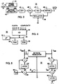
- Fig. 7 is a timing diagram illustrating the sampling and quota updates in a system using the first approach.
- channel 1 is an example of a channel transmitting standard video having a frame rate of 30 frames per second (in the U.S.).
- Channel 2 is an example of a channel transmitting a film having a frame rate of 24 frames per second.
- Each of the channels is assumed to have 12 frames per GOP.
- Channel 1 thus, starts a new GOP every 0.4 seconds, or 2.5 GOPs per second, while channel 2 starts a new GOP every 0.5 seconds, or 2 GOPs per second.
- the sampling rate selected is one sample every 0.1 seconds.
- channel 1 there are four sample and quota updates in every GOP, and in channel 2 there are five sample and quota updates in every GOP.
- the sampling times, t s are illustrated by vertical dashed lines. Because the time periods between samples ⁇ t is constant (0.1 seconds), equations (3) through (12), above, may be used without any modification in calculating the bit rate allocations for the next sample period. These bit rate allocations may be accumulated and used in the channel processors 10 (of Fig. 1 ) according to the known scheme termed the "token and leaky bucket" scheme.
- Fig. 8 is a timing diagram illustrating the sampling of coding complexity values and quota updating in a system using the second approach, described above.
- the respective channels illustrated in Fig. 8 are carrying the same signals as in Fig. 7 .
- samples of the coding complexity values from all the channels are taken whenever any channel begins a new GOP. New allocations are generated based on the values of those samples, and the time period ⁇ t since the last sample.
- These sample times are illustrated in Fig. 8 as vertical dashed lines t1 - t8, where t2, t3, t4, t6 and t8 correspond to starts of GOPs in channel 1, and t1, t3, t5 and t7 correspond to starts of GOPs in channel 2.
- t3 illustrates a sampling time corresponding to starts of GOPs in both channel 1 and 2, there is no requirement that such a time occur.
- Equations (3) through (12) may be used to calculate the next bit rate quota proportions, but in determining the actual number of bits available to be allocated, the amount of time ⁇ t since the last sample must be taken into account.
- the number of bits calculated by equations (3) through (12) are then allocated to the respective channel processors 10 (of Fig. 1 ) which, as above, use the "token and leaky bucket" scheme to accumulate and use the allocated bits. Either of the above two above approaches will accurately allocate bit rates to the respective channel processors 10 when the video signals from the different channels 5 have different GOP time periods.
- Fig. 6 is a timing diagram illustrating coding complexity sample and quota update timing in such a system.
- each horizontal line corresponds to a respective channel I - K.
- the short vertical lines extending upward from the horizontal lines represent the time when coding of an I frame is begun for that channel, which is considered to be the beginning of a GOP for that channel.
- the time period for a GOP, GOP time is equal in all of the channels, but, as can be seen, the beginning times of the GOPs for the respective channels are different. In fact, it has been found desirable to have different starting times for the GOPs for the respective channels so that coding of I frames do not overlap. This increases the complexity variations across the different channels.
- a coding complexity value sample may be taken simultaneously from all the channels at any time within a GOP. Updates of the bit rate quotas for all of the channels may then be generated from that sample and transmitted back to the channel processors 10 (of Fig. 1 ).
- the above multiplexer system has been described as a collocated system.
- the plurality 10 of channel processors could reside in remote locations from the bit rate allocator 30 and the multiplexer 20.
- communication links would be established between the encoders and the bit rate allocator.
- some portion of the bits transmitted between the processors 10 and the multiplexer could be dedicated to transmission of complexity information from the processors.
Landscapes
- Engineering & Computer Science (AREA)
- Signal Processing (AREA)
- Multimedia (AREA)
- Computer Networks & Wireless Communication (AREA)
- Compression Or Coding Systems Of Tv Signals (AREA)
- Time-Division Multiplex Systems (AREA)
Claims (18)
- Système de multiplexage comportant :- une pluralité de sources (5) de signaux de données représentant des séquences respectives d'images s'étendant sur une durée donnée de groupe d'images (GOP- Group of Pictures) ;- un multiplexeur (20) comportant une pluralité de bornes d'entrée (1 à K) et une borne de sortie (15),- une pluralité de processeurs de canaux (10), chacun comportant une borne d'entrée de données connectée à une des sources (5) respectives, une borne de sortie de complexité conçue pour générer un signal représentatif de la complexité de l'ensemble de la séquence d'images représentée par le signal de données au niveau de la borne d'entrée de données, une borne d'entrée de commande et une borne de sortie de données connectée à une des bornes d'entrée respectives (1 à K) du multiplexeur (20) et conçue pour générer un signal codé à débit binaire constant fixé en fonction du signal au niveau de la borne d'entrée de commande ; et- un dispositif d'affectation de débit binaire (30), comportant une pluralité de paires de bornes d'entrée et de sortie associées, chaque paire étant associée avec un processeur de canaux respectif, la borne d'entrée de chaque paire étant connectée à la borne de sortie de complexité du processeur de canaux associé, et la borne de sortie de chaque paire étant connectée à la borne d'entrée de commande du processeur de canaux associé et conçue pour générer un signal de quota de débit binaire de façon à ce que à chaque processeur de canaux (10) soit affecté un débit binaire en relation avec la complexité représentée par le signal au niveau de la borne d'entrée associée et avec la complexité combinée représentée par les signaux aux niveau des bornes d'entrée de l'ensemble de la pluralité des paires, dans lequel :- ledit multiplexeur (20) est conçu pour générer un signal au niveau de sa borne de sortie (15) qui a un débit binaire prédéterminé constant,- chaque source de signaux (5) est conçue pour générer un signal de données qui est un signal vidéo comportant des données d'image de ladite séquence d'images comportant un certain nombre de trames, dans laquelle ladite durée donnée du groupe GOP est identique pour chaque processeur de la pluralité de processeurs de canaux,- chaque processeur de canaux (10) est conçu pour générer le signal représentatif de la complexité pendant le codage de la séquence d'images représentée par le signal de données au niveau de la borne d'entrée de données du processeur de canaux ; et- le dispositif d'affectation de débit binaire (30) est conçu pour générer un signal séparé de quota de débit binaire pour chaque processeur de canaux, les signaux séparés de quota de débit binaire étant valables pour la totalité de la durée du groupe GOP qui suit la durée donnée du groupe GOP, selon les signaux représentatifs de la complexité, de telle façon qu'à chaque processeur de canaux (10) soit affectée une proportion du débit binaire constant prédéterminé en fonction de la proportion de la complexité représentée par le signal au niveau de la borne d'entrée de chaque paire associée à la complexité combinée représentée par les signaux au niveau des bornes d'entrée de la pluralité des paires.
- Système de multiplexage selon la revendication 1, dans lequel le dispositif d'affectation de débit binaire (30) est conçu pour générer des signaux de quota de débit binaire respectifs au niveau de la borne de sortie de chaque paire de bornes d'entrée et de sortie associée de façon à ce qu'un processeur de canaux (10) ayant un signal de complexité de niveau relativement important au niveau de sa borne d'entrée de données reçoive un signal de quota de débit binaire de niveau relativement plus élevé qu'un processeur de canaux (10) ayant un signal de complexité relativement moins important.
- Système de multiplexage selon la revendication 2, dans lequel :- le multiplexeur (20) est conçu pour générer un signal au niveau de sa borne de sortie ayant un débit binaire prédéterminé constant ;- à chaque processeur de canaux (10) est affecté un débit binaire respectif prédéterminé minimal ; et- le dispositif d'affectation de débit binaire (30) est conçu pour générer des signaux de quota de débit binaire respectifs au niveau de la borne de sortie de chaque paire associée de bornes d'entrée et de sortie, de façon à ce que à chaque processeur de canaux (10) soit affecté le débit binaire prédéterminé minimal prévu, et en outre une proportion de débit binaire restant, le débit binaire restant étant égal au débit binaire constant prédéterminé moins les débits binaires minimaux prédéterminés précédemment affectés, la proportion affectée en outre étant égale à la proportion de la complexité représentée par le signal au niveau de la borne d'entrée de la paire associée à la complexité combinée représentée par les signaux au niveau des bornes d'entrée de toutes les paires.
- Système de multiplexage selon la revendication 2, dans lequel :- le multiplexeur (20) est conçu pour générer un signal au niveau de sa borne de sortie (15) ayant un débit binaire constant ;- à chaque processeur de canaux (10) est affecté un facteur de pondération respectif prédéterminé ; et- le dispositif d'affectation de débit binaire (30) est conçu pour générer des signaux de quota de débit binaire respectifs au niveau de la borne de sortie de chaque paire de bornes d'entrée et de sortie associée de façon à ce qu'à chaque processeur de canaux soit affectée une proportion du débit binaire constant prédéterminé égale à la proportion de la complexité représentée par le signal au niveau de la borne d'entée de la paire associée à la complexité combinée représentée par les signaux au niveau des bornes d'entrée de la pluralité des paires, pondérée par le facteur de pondération prédéterminé affecté au processeur de canaux associé.
- Système de multiplexage selon la revendication 2, dans lequel :- le multiplexeur (20) est conçu pour générer un signal au niveau de sa borne de sortie (15) ayant un débit binaire prédéterminé constant ;- à chaque processeur de canaux (10) est affecté un débit binaire respectif prédéterminé minimal et un facteur de pondération prédéterminé ; et- le dispositif d'affectation de débit binaire (30) est conçu pour générer des signaux respectifs de quota de débit binaire au niveau de la borne de sortie de chaque paire de bornes d'entrée et de sortie associée de façon à ce qu'à ce que à chaque processeur de canaux soit affecté son débit binaire prédéterminé minimal et en outre une proportion du débit binaire restant, le débit binaire restant étant égal au débit binaire constant prédéterminé moins les débits binaires minimaux prédéterminés précédemment affectés, la proportion affectée en outre étant égale à la proportion de la complexité représentée par le signal au niveau de la borne d'entrée de la paire associée à la complexité combinée représentée par les signaux au niveau des bornes d'entrée de toutes les paires, pondérée par le facteur de pondération prédéterminé affecté au processeur de canaux associé.
- Système de multiplexage selon la revendication 2, dans lequel :- à chaque processeur de canaux (10) est affectée une limite respective d'affectation de débit binaire prédéterminée ; et- le dispositif d'affectation de débit binaire (30), après la génération des signaux de quota de débit binaire respectifs qui affectent des débits binaires aux processeurs de canaux respectifs (10), est conçu pour comparer les affectations de débits binaires respectives aux limites respectives prédéterminées d'affectation de débit binaire, et si une affectation de débit binaire dépasse la limite d'affectation de débit binaire prédéterminée, pour générer un signal de quota de débit binaire représentant la limité prédéterminée d'affectation de débit binaire, au lieu de l'affectation précédemment générée de débit binaire pour le processeur de canaux associé.
- Système de multiplexage selon la revendication 6, dans lequel la limite prédéterminée d'affectation de débit binaire est une affectation maximale de débit binaire.
- Système de multiplexage selon la revendication 6, dans lequel la limite prédéterminée d'affectation de débit binaire est une affectation minimale de débit binaire.
- Système de multiplexage selon la revendication 2, dans lequel :- à chaque processeur de canaux (10) et affecté un incrément de limite respectif prédéterminé d'affectation de débit binaire ; et- le dispositif d'affectation de débit binaire (30), après avoir généré les signaux respectifs de quota de débit binaire qui représentent les débits binaires affectés aux processeurs de canaux (10) associés, est conçu pour comparer les affectations respectives de débit binaire aux affectations de débit binaire correspondant représentées par les signaux respectifs de quota de débit binaire qui précèdent immédiatement pour déterminer les incréments d'affectation de débit binaire respectifs, et si un incrément d'affectation de débit binaire dépasse une limite d'incrément d'affectation de débit binaire prédéterminée affectée, pour générer un signal de quota de débit binaire qui représente l'affectation de débit binaire représentée par le signal de quota de débit binaire respectif immédiatement précédent modifiée par la limite d'incrément d'affectation de débit binaire prédéterminée, au lieu de l'affectation de débit binaire précédemment générée pour le processeur de canaux associé.
- Système de multiplexage selon la revendication 9, dans lequel la limite d'incrément de débit binaire prédéterminée est un incrément maximal d'augmentation du débit binaire.
- Système de multiplexage selon la revendication 9, dans lequel la limite d'incrément de débit binaire prédéterminée est un incrément maximal de diminution du débit binaire.
- Système de multiplexage selon la revendication 2, dans lequel :- chaque processeur de canaux (10) comprend une mémoire tampon de sortie (48) dont la capacité permet d'enregistrer temporairement les données à fournir au multiplexeur (20) pendant une certaine durée ; et- le dispositif d'affectation de débit binaire (30), après la génération des signaux de quota de débit binaire respectifs qui représentent les débits binaires affectés aux processeurs de canaux (10), est conçu pour comparer les affectations de débit binaire aux affectations de débit binaire correspondantes représentées par les signaux de quota de débit binaire respectifs qui précèdent immédiatement, et si une affectation de débit binaire a diminué, pour déterminer si les données enregistrées temporairement dans la mémoire tapon de sortie du processeur de canaux du processeur de canaux associé seront fournies au multiplexeur (20) pendant la durée prédéterminée d'affectation diminuée de débit binaire, et sinon, pour générer un signal de quota de débit binaire qui représente une nouvelle affectation de débit binaire qui permettra aux données temporairement enregistrées dans la mémoire tampon de sortie du processeur de canaux associé d'être fournies au multiplexeur (20) pendant la durée prédéterminée, au lieu de l'affectation de débit binaire précédemment générée pour le processeur de canaux associé.
- Système de multiplexage selon a revendication 1, dans lequel :chacun des processeurs de la pluralité de processeurs de canaux (10) comporte :- un codeur à débit binaire constant (14) ayant un trajet de données connecté entre la borne d'entrée de données (5) et la borne de sortie de données du processeur de canaux (10), et une borne d'entrée de quota (0) connectée à la borne d'entrée de commande (CONTROL) du processeur de canaux (10), pour générer le signal codé ; et- un analyseur de complexité (16) connecté entre la borne d'entrée de données (5) et la borne de sortie de complexité (COMPLEXITY) du processeur de canaux (10), afin d'analyser la complexité du signal au niveau de la borne d'entrée de données (5), et de générer le signal représentatif de la complexité.
- Système de multiplexage selon la revendication 13, dans lequel :le codeur à débit binaire constant (14) comporte :- un quantificateur variable (46) connecté au trajet de données du codeur à débit binaire constant (14) et comportant une borne d'entrée de commande (QMB) pour générer un signal quantifié ayant une valeur de pas de quantification défini en fonction du signal au niveau de la borne d'entrée de commande (OMB) ; et- un régulateur de débit binaire (49) connecté entre la borne de sortie de données (TMB) du processeur de canaux (10) et la borne d'entrée de commande (QMB) du quantificateur variable (49), pour faire varier la valeur du pas de quantification en fonction du débit binaire du signal codé au niveau de la borne de sortie ( DATA OUT) du codeur à débit binaire constant (14) et du signal au niveau de la borne d'entrée de quota (Q) du codeur à débit binaire constant (14) ; et dans lequel :- l'analyseur de complexité (16) comporte :- des circuits de détermination de complexité (92 à 99) comportant des bornes d'entrée respectives connectées à la borne d'entrée de commande (QMB) du quantificateur variable (46) et à la borne de sortie du codeur à débit binaire constant (DATA OUT), afin de générer le signal représentatif de la complexité (Xpic) qui est fonction de la valeur moyenne du pas de quantification et du débit binaire du signal codé au niveau de la borne de sortie du codeur à débit binaire constant (DATA OUT).
- Système de multiplexage selon la revendication 14, dans lequel les circuits de détermination de complexité (92 à 99) sont conçus pour générer le signal représentatif de la complexité (Xpic) qui est directement proportionnel à la valeur moyenne de pas de quantification (QMB) et au débit binaire (TMB) du signal codé au niveau de la borne de sortie du codeur à débit binaire constant (DATA OUT).
- Système de multiplexage selon la revendication 15, dans lequel les circuits de détermination de complexité (92 à 99) sont conçus pour générer le signal représentatif de la complexité (Xpic) qui est le produit de la valeur moyenne du pas de quantification (QMB) par le débit binaire (TMB) du signal codé au niveau de la borne de sortie du codeur à débit binaire constant (DATA OUT).
- Système de multiplexage selon la revendication 13, dans lequel codeur à débit binaire constant (14) comporte :- un quantificateur variable (46) connecté dans le trajet de données du codeur à débit binaire constant (14) et ayant une borne d'entrée de commande (QMB) pour générer un signal quantifié dont la valeur du pas de quantification est définie en fonction du signal de valeur de pas de quantification au niveau de la borne d'entrée de commande ; et- un régulateur de débit binaire (49) connecté entre la borne de sortie de données (DATA OUT) du processeur de canaux (10) et la borne d'entrée de commande (QMB) du quantificateur variable (46) et ayant une borne d'entrée de commande de débit binaire (Q) connectée à la borne de sortie de la paire associée de bornes d'entrée et de sortie du dispositif d'affectation de débit binaire (30), afin de générer le signal de valeur de pas de quantification au niveau de l'entrée de commande terminal (QMB) du quantificateur variable (46) pour commander la valeur du pas de quantification en fonction du débit binaire du signal codé au niveau de la borne de sortie du codeur à débit binaire constant (DATA OUT) et du signal au niveau de la borne d'entrée de commande de débit binaire (Q) ; et dans lequel :l'analyseur de complexité (16) comporte :- des circuits de détermination de complexité (92 à 99) ayant des bornes d'entrée respectives connectées à la bornes d'entrée de commande (QMB) du quantificateur variable (46) et à la borne de sortie du codeur à débit binaire constant (DATA OUT), afin de générer le signal représentatif de la complexité (Xpic) qui est fonction de la valeur moyenne du pas de quantification et du débit binaire du signal codé au niveau de la borne de sortie (DATA OUT) du codeur à débit binaire constant(14).
- Système de multiplexage selon la revendication 17, dans lequel :- le codeur à débit binaire constant (14) est conçu pour fonctionner selon le standard MPEG (Motion Picture Experts Group), à savoir diviser chaque image séquentielle du signal vidéo au niveau de sa borne d'entrée de données (5) en un nombre prédéterminé (NMB) de macroblocs et coder séquentiellement chacun des nombres prédéterminés (NMB) de macroblocs en nombres respectifs de bits (TMB) au niveau de sa borne de sortie de données (DATA OUT) pour générer une séquence d'images codées ;- le régulateur de débit binaire (49) est conçu pour générer des signaux respectifs de commande de valeur de pas de quantification (QMB) pour chacun des nombres prédéterminés (NMB) de macroblocs ; et- les circuits de détermination de complexité (92 à 99) comportent :- un premier accumulateur (92, 93) connecté à la borne de sortie de données du codeur à débit binaire constant (DATA OUT), pour faire la somme des nombres respectifs de bits (TMB) générés au niveau de la borne de sortie de données (DATA OUT) du codeur à débit binaire constant (14) pour chaque macrobloc codé, pour générer le nombre total de bits (Tpic) dans chacune des images séquentielles codées ;- un deuxième accumulateur (96, 97) connecté au régulateur de débit binaire (49) pour faire la somme des signaux respectifs de valeur de pas de quantification (QMB) pour chaque macrobloc de chacune des images séquentielles ;- un circuit de calcul de moyenne (98, 99) connecté au deuxième accumulateur (96, 97) pour calculer la valeur moyenne du pas de quantification pour le nombre prédéterminé (NMB) de macroblocs dans chacune des images séquentielles, pour générer un signal de valeur moyenne du pas de quantification (QMB) pour chacune des images séquentielles ;- un multiplicateur (94) connecté au premier accumulateur (92, 93) et au circuit de calcul de moyenne (98, 99), pour multiplier le nombre total de bits (T pic) par le signal de valeur moyenne du pas de quantification (QMB), pour générer un signal de complexité d'image (Xpic) pour chacune des images séquentielles ; et- un troisième accumulateur (94, 95) pour faire la somme des signaux respectifs de complexité d'image pour chacune des images d'un groupe d'images, pour générer le signal représentatif de la complexité (XGOP).
Applications Claiming Priority (1)
| Application Number | Priority Date | Filing Date | Title |
|---|---|---|---|
| PCT/US1994/004333 WO1995029559A1 (fr) | 1994-04-20 | 1994-04-20 | Systeme multiplexeur mettant en ×uvre des codeurs a debit binaire constant |
Publications (3)
| Publication Number | Publication Date |
|---|---|
| EP0803163A1 EP0803163A1 (fr) | 1997-10-29 |
| EP0803163A4 EP0803163A4 (fr) | 1998-05-20 |
| EP0803163B1 true EP0803163B1 (fr) | 2009-07-08 |
Family
ID=22242479
Family Applications (1)
| Application Number | Title | Priority Date | Filing Date |
|---|---|---|---|
| EP94916545A Expired - Lifetime EP0803163B1 (fr) | 1994-04-20 | 1994-04-20 | Systeme multiplexeur mettant en uvre des codeurs a debit binaire constant |
Country Status (6)
| Country | Link |
|---|---|
| EP (1) | EP0803163B1 (fr) |
| JP (1) | JPH09512396A (fr) |
| KR (1) | KR100314329B1 (fr) |
| AU (1) | AU6816094A (fr) |
| DE (1) | DE69435216D1 (fr) |
| WO (1) | WO1995029559A1 (fr) |
Families Citing this family (12)
| Publication number | Priority date | Publication date | Assignee | Title |
|---|---|---|---|---|
| US5805220A (en) * | 1995-02-22 | 1998-09-08 | U.S. Philips Corporation | System for transmitting a plurality of video programs simultaneously through a transmission channel |
| US5835498A (en) * | 1995-10-05 | 1998-11-10 | Silicon Image, Inc. | System and method for sending multiple data signals over a serial link |
| US5862140A (en) * | 1995-11-21 | 1999-01-19 | Imedia Corporation | Method and apparatus for multiplexing video programs for improved channel utilization |
| US5956088A (en) * | 1995-11-21 | 1999-09-21 | Imedia Corporation | Method and apparatus for modifying encoded digital video for improved channel utilization |
| US5877812A (en) * | 1995-11-21 | 1999-03-02 | Imedia Corporation | Method and apparatus for increasing channel utilization for digital video transmission |
| US5793425A (en) * | 1996-09-13 | 1998-08-11 | Philips Electronics North America Corporation | Method and apparatus for dynamically controlling encoding parameters of multiple encoders in a multiplexed system |
| FR2764156B1 (fr) | 1997-05-27 | 1999-11-05 | Thomson Broadcast Systems | Dispositif de pretraitement pour codage mpeg ii |
| KR100495101B1 (ko) * | 1997-12-24 | 2005-09-30 | 주식회사 팬택앤큐리텔 | 무선가입자망 시스템에서의 기지국내 트래픽 데이터다중/역다중 처리장치 |
| US6570922B1 (en) | 1998-11-24 | 2003-05-27 | General Instrument Corporation | Rate control for an MPEG transcoder without a priori knowledge of picture type |
| JP2003531533A (ja) | 2000-04-18 | 2003-10-21 | コーニンクレッカ フィリップス エレクトロニクス エヌ ヴィ | ジョイントビットレートトランスコーディングにおけるビットレートアロケーション |
| WO2011075160A1 (fr) * | 2009-12-14 | 2011-06-23 | Thomson Licensing | Procédé de multiplexage statistique de diffusion |
| US20140112386A1 (en) * | 2012-10-22 | 2014-04-24 | General Instrument Corporation | Algorithms for determining bitrate for a statistical multiplexing system to account for signal complexity including film mode and gop structural changes |
Family Cites Families (9)
| Publication number | Priority date | Publication date | Assignee | Title |
|---|---|---|---|---|
| CA1253255A (fr) * | 1983-05-16 | 1989-04-25 | Nec Corporation | Systeme de codage et de decodage simultanee de signaux multiples |
| JPH0624341B2 (ja) * | 1986-12-18 | 1994-03-30 | 三菱電機株式会社 | マルチメディアデータ伝送方式 |
| EP0418396B1 (fr) * | 1989-03-16 | 1998-06-03 | Fujitsu Limited | Systeme de transmission multiplex video/audio |
| IT1237668B (it) * | 1989-10-31 | 1993-06-15 | Telettra Lab Telefon | Sistema e multiplatore/demultiplatore per la trasmissione/ricezione di informazione digitale televisiva. |
| US5134476A (en) * | 1990-03-30 | 1992-07-28 | At&T Bell Laboratories | Video signal encoding with bit rate control |
| US5115309A (en) * | 1990-09-10 | 1992-05-19 | At&T Bell Laboratories | Method and apparatus for dynamic channel bandwidth allocation among multiple parallel video coders |
| US5231484A (en) * | 1991-11-08 | 1993-07-27 | International Business Machines Corporation | Motion video compression system with adaptive bit allocation and quantization |
| JP2500582B2 (ja) * | 1993-03-17 | 1996-05-29 | 日本電気株式会社 | 動画像信号の多重化伝送方法とその装置 |
| BE1007490A3 (nl) * | 1993-09-10 | 1995-07-11 | Philips Electronics Nv | Inrichting voor het overdragen van een pluraliteit van televisie signalen over een transmissie kanaal. |
-
1994
- 1994-04-20 JP JP7527600A patent/JPH09512396A/ja active Pending
- 1994-04-20 WO PCT/US1994/004333 patent/WO1995029559A1/fr active Application Filing
- 1994-04-20 AU AU68160/94A patent/AU6816094A/en not_active Abandoned
- 1994-04-20 KR KR1019960705919A patent/KR100314329B1/ko not_active IP Right Cessation
- 1994-04-20 EP EP94916545A patent/EP0803163B1/fr not_active Expired - Lifetime
- 1994-04-20 DE DE69435216T patent/DE69435216D1/de not_active Expired - Lifetime
Also Published As
| Publication number | Publication date |
|---|---|
| DE69435216D1 (de) | 2009-08-20 |
| AU6816094A (en) | 1995-11-16 |
| EP0803163A4 (fr) | 1998-05-20 |
| EP0803163A1 (fr) | 1997-10-29 |
| JPH09512396A (ja) | 1997-12-09 |
| WO1995029559A1 (fr) | 1995-11-02 |
| KR100314329B1 (ko) | 2001-12-28 |
| KR970702663A (ko) | 1997-05-13 |
Similar Documents
| Publication | Publication Date | Title |
|---|---|---|
| US6055270A (en) | Multiplexer system using constant bit rate encoders | |
| US5838686A (en) | System for dynamically allocating a scarce resource | |
| US5933451A (en) | Complexity determining apparatus | |
| EP0758509B1 (fr) | Procede et appareil pour empecher un depassement de capacite positif ou negatif dans un tampon de codeur, d'un systeme de compression video | |
| US5694170A (en) | Video compression using multiple computing agents | |
| US5719632A (en) | Motion video compression system with buffer empty/fill look-ahead bit allocation | |
| US6181742B1 (en) | Single pass target allocation for video encoding | |
| US5877814A (en) | Asynchronous control signal generating apparatus | |
| EP0803163B1 (fr) | Systeme multiplexeur mettant en uvre des codeurs a debit binaire constant | |
| US5864583A (en) | Parameter sampling apparatus | |
| EP0761048B1 (fr) | Systeme d'attribution dynamique d'une ressource disponible en faible quantite | |
| US5933450A (en) | Complexity determining apparatus | |
| EP0756790B1 (fr) | Generateur asynchrone de signaux de commande | |
| EP0756793B1 (fr) | Appareil pour determiner le niveau de complexite pour regler le codage d'un signal video | |
| EP0756789B1 (fr) | Appareil de determination de complexite | |
| EP0756788B1 (fr) | Echantillonneur de parametres | |
| CN1078782C (zh) | 异步控制信号发生装置 | |
| CN1067203C (zh) | 利用恒定位率编码器的多路复用系统 | |
| CN1080960C (zh) | 参数抽样装置 |
Legal Events
| Date | Code | Title | Description |
|---|---|---|---|
| PUAI | Public reference made under article 153(3) epc to a published international application that has entered the european phase |
Free format text: ORIGINAL CODE: 0009012 |
|
| 17P | Request for examination filed |
Effective date: 19961014 |
|
| AK | Designated contracting states |
Kind code of ref document: A1 Designated state(s): DE FR GB |
|
| RHK1 | Main classification (correction) |
Ipc: H04J 3/16 |
|
| A4 | Supplementary search report drawn up and despatched |
Effective date: 19980401 |
|
| AK | Designated contracting states |
Kind code of ref document: A4 Designated state(s): DE FR GB |
|
| 17Q | First examination report despatched |
Effective date: 20020612 |
|
| RAP1 | Party data changed (applicant data changed or rights of an application transferred) |
Owner name: THOMSON INC. |
|
| APBN | Date of receipt of notice of appeal recorded |
Free format text: ORIGINAL CODE: EPIDOSNNOA2E |
|
| APBR | Date of receipt of statement of grounds of appeal recorded |
Free format text: ORIGINAL CODE: EPIDOSNNOA3E |
|
| APAF | Appeal reference modified |
Free format text: ORIGINAL CODE: EPIDOSCREFNE |
|
| APBT | Appeal procedure closed |
Free format text: ORIGINAL CODE: EPIDOSNNOA9E |
|
| GRAP | Despatch of communication of intention to grant a patent |
Free format text: ORIGINAL CODE: EPIDOSNIGR1 |
|
| GRAS | Grant fee paid |
Free format text: ORIGINAL CODE: EPIDOSNIGR3 |
|
| GRAA | (expected) grant |
Free format text: ORIGINAL CODE: 0009210 |
|
| AK | Designated contracting states |
Kind code of ref document: B1 Designated state(s): DE FR GB |
|
| REG | Reference to a national code |
Ref country code: GB Ref legal event code: FG4D |
|
| REF | Corresponds to: |
Ref document number: 69435216 Country of ref document: DE Date of ref document: 20090820 Kind code of ref document: P |
|
| PLBE | No opposition filed within time limit |
Free format text: ORIGINAL CODE: 0009261 |
|
| STAA | Information on the status of an ep patent application or granted ep patent |
Free format text: STATUS: NO OPPOSITION FILED WITHIN TIME LIMIT |
|
| 26N | No opposition filed |
Effective date: 20100409 |
|
| PGFP | Annual fee paid to national office [announced via postgrant information from national office to epo] |
Ref country code: GB Payment date: 20100330 Year of fee payment: 17 |
|
| PGFP | Annual fee paid to national office [announced via postgrant information from national office to epo] |
Ref country code: FR Payment date: 20100429 Year of fee payment: 17 |
|
| PGFP | Annual fee paid to national office [announced via postgrant information from national office to epo] |
Ref country code: DE Payment date: 20100419 Year of fee payment: 17 |
|
| REG | Reference to a national code |
Ref country code: DE Ref legal event code: R119 Ref document number: 69435216 Country of ref document: DE |
|
| REG | Reference to a national code |
Ref country code: DE Ref legal event code: R119 Ref document number: 69435216 Country of ref document: DE |
|
| GBPC | Gb: european patent ceased through non-payment of renewal fee |
Effective date: 20110420 |
|
| REG | Reference to a national code |
Ref country code: FR Ref legal event code: ST Effective date: 20111230 |
|
| PG25 | Lapsed in a contracting state [announced via postgrant information from national office to epo] |
Ref country code: FR Free format text: LAPSE BECAUSE OF NON-PAYMENT OF DUE FEES Effective date: 20110502 |
|
| PG25 | Lapsed in a contracting state [announced via postgrant information from national office to epo] |
Ref country code: GB Free format text: LAPSE BECAUSE OF NON-PAYMENT OF DUE FEES Effective date: 20110420 |
|
| PG25 | Lapsed in a contracting state [announced via postgrant information from national office to epo] |
Ref country code: DE Free format text: LAPSE BECAUSE OF NON-PAYMENT OF DUE FEES Effective date: 20111031 |