EP0803116B1 - Harmonische und frequenzstarre grundfrequenz-folgeschaltung sowie system zur trennung von geräuschen - Google Patents
Harmonische und frequenzstarre grundfrequenz-folgeschaltung sowie system zur trennung von geräuschen Download PDFInfo
- Publication number
- EP0803116B1 EP0803116B1 EP96902649A EP96902649A EP0803116B1 EP 0803116 B1 EP0803116 B1 EP 0803116B1 EP 96902649 A EP96902649 A EP 96902649A EP 96902649 A EP96902649 A EP 96902649A EP 0803116 B1 EP0803116 B1 EP 0803116B1
- Authority
- EP
- European Patent Office
- Prior art keywords
- signal
- frequency
- input signal
- tracking error
- demodulation
- Prior art date
- Legal status (The legal status is an assumption and is not a legal conclusion. Google has not performed a legal analysis and makes no representation as to the accuracy of the status listed.)
- Expired - Lifetime
Links
- 238000000926 separation method Methods 0.000 title description 2
- 230000036961 partial effect Effects 0.000 claims description 55
- 238000000034 method Methods 0.000 claims description 30
- 230000003111 delayed effect Effects 0.000 claims description 14
- 238000001914 filtration Methods 0.000 claims description 8
- 230000008859 change Effects 0.000 claims description 7
- 238000001514 detection method Methods 0.000 claims description 5
- 238000009499 grossing Methods 0.000 claims description 3
- 230000008878 coupling Effects 0.000 claims description 2
- 238000010168 coupling process Methods 0.000 claims description 2
- 238000005859 coupling reaction Methods 0.000 claims description 2
- 230000001934 delay Effects 0.000 claims 1
- 230000000737 periodic effect Effects 0.000 description 9
- 238000005070 sampling Methods 0.000 description 8
- 239000000203 mixture Substances 0.000 description 7
- 230000002238 attenuated effect Effects 0.000 description 6
- 238000012937 correction Methods 0.000 description 4
- 238000002955 isolation Methods 0.000 description 4
- 230000008569 process Effects 0.000 description 3
- 230000005236 sound signal Effects 0.000 description 3
- 238000001228 spectrum Methods 0.000 description 3
- 238000000605 extraction Methods 0.000 description 2
- 230000004048 modification Effects 0.000 description 2
- 238000012986 modification Methods 0.000 description 2
- 229920006395 saturated elastomer Polymers 0.000 description 2
- 238000005311 autocorrelation function Methods 0.000 description 1
- 230000009286 beneficial effect Effects 0.000 description 1
- 230000015572 biosynthetic process Effects 0.000 description 1
- 238000004364 calculation method Methods 0.000 description 1
- 230000008030 elimination Effects 0.000 description 1
- 238000003379 elimination reaction Methods 0.000 description 1
- 238000010606 normalization Methods 0.000 description 1
- 230000004044 response Effects 0.000 description 1
- 238000003786 synthesis reaction Methods 0.000 description 1
- 230000001131 transforming effect Effects 0.000 description 1
- 238000004804 winding Methods 0.000 description 1
Images

Classifications
-
- G—PHYSICS
- G10—MUSICAL INSTRUMENTS; ACOUSTICS
- G10L—SPEECH ANALYSIS TECHNIQUES OR SPEECH SYNTHESIS; SPEECH RECOGNITION; SPEECH OR VOICE PROCESSING TECHNIQUES; SPEECH OR AUDIO CODING OR DECODING
- G10L25/00—Speech or voice analysis techniques not restricted to a single one of groups G10L15/00 - G10L21/00
- G10L25/90—Pitch determination of speech signals
- G10L2025/906—Pitch tracking
-
- G—PHYSICS
- G10—MUSICAL INSTRUMENTS; ACOUSTICS
- G10L—SPEECH ANALYSIS TECHNIQUES OR SPEECH SYNTHESIS; SPEECH RECOGNITION; SPEECH OR VOICE PROCESSING TECHNIQUES; SPEECH OR AUDIO CODING OR DECODING
- G10L25/00—Speech or voice analysis techniques not restricted to a single one of groups G10L15/00 - G10L21/00
- G10L25/03—Speech or voice analysis techniques not restricted to a single one of groups G10L15/00 - G10L21/00 characterised by the type of extracted parameters
- G10L25/15—Speech or voice analysis techniques not restricted to a single one of groups G10L15/00 - G10L21/00 characterised by the type of extracted parameters the extracted parameters being formant information
Definitions
- the present invention relates generally to pitch tracking systems, methods for tracking the pitch of a quasi periodic sound source and for the separation of periodic signals from mixtures of sounds.
- Pitch tracking is of interest whenever a single quasi periodic sound source is to be studied or modeled.
- the trajectory of a sound's pitch also called the fundamental frequency
- An example of a quasi periodic sound source is a singer's voice singing a particular note (e.g., high C).
- the sound generated by the singer typically has a certain amount of vibrato or pitch modulation, noise and aperiodicity in the wave shape, making the sound quasi periodic rather than a pure periodic signal.
- pitch detection methods can be classified into three categories: Fourier-based frequency domain techniques, time domain techniques, and methods which use both techniques.
- the present invention is a time domain technique.
- time domain “feature detection methods” the input signal is usually preprocessed to accentuate some time domain feature, and the time between occurrences of that feature is calculated as the period of the signal.
- a typical time domain feature detector includes a low pass filter for detecting peaks or zero crossings of the filtered signal. Since the time between occurrences of a particular feature is used as the period estimate, feature detection schemes usually do not use all of the data available. Selection of a different feature often yields a different set of pitch estimates. Since estimates of the period are often defined at the instant when the features are detected, the frequency samples yielded are not uniformly distributed in time. To avoid the problem of non-uniform time sampling a window of fixed size can be moved through the signal in order to obtain an averaged period estimate.
- RISC An improved Costas Estimator-Predictor, Filter Bank for Decomposing Multicomponent Signals, Proc. 7th SSAP Workshop, 1994, pp 207-210.
- a frequency-locked loop pitch tracker as set out in claim 1 and a frequency-locked loop method for tracking an input signal as set out in claim 8.
- the present invention is a system and method for tracking the pitch of a quasi periodic signal in a mixture of signals.
- the quasi periodic signal is "frequency warped" by selectively frequency modulating it, thereby resulting in a signal that is stationary and is a simplified spectrum which is more amenable to analysis.
- the resultant demodulated signal is low pass filtered resulting in an analytic signal whose phase winding rate is the frequency mismatch error between the target signal and the demodulating signal.
- the phase is differenced by multiplying the signal with a delayed version of itself creating an instantaneous autocorrelation. Thereafter the phase difference is measured with a complex arctangent to yield a resulting phase error.
- the resulting phase error is input to an integrator whose output value is the estimate of the frequency. This output frequency parameter is then used to update the demodulating signal thus closing the signal loop.
- a plurality of frequency locked loop trackers are servoed together centering each one of the trackers on a multiple of the fundamental frequency of the input signal.
- the resulting phase errors derived from the frequency lock loop trackers are weighted to improve system performance.
- the frequency corrections from each tracker are weighted with the inverse variance of its tracking performance. Accordingly, harmonics with low variance are weighted strongly, and harmonics in a noisy region of the spectrum and thus high variance will be weighted less strongly.
- the resulting fundamental frequency estimate is a minimum-variance estimate, and is better than the best single frequency locked loop estimate.
- the weighted phase error is then fed back to an integrator to yield a high resolution estimate of the target signal fundamental frequency and all of its harmonics.
- the amplitude envelopes for each partial signal can be easily extracted and used in conjunction with the fundamental estimate from each frequency lock loop tracker to resynthesize the signal in isolation from the mixture. Since the resynthesized signal is in phase with the original signal, the target may be removed from the mixture by subtraction.
- the first step in the analysis of the input signal z[n] 102 is to demodulate the input signal by means of a frequency matched demodulation signal.
- the input signal z [n] 102 is demodulated by multiplier 104, which multiplies the input signal z[n] with the complex conjugate of a frequency warping signal ⁇ [n] 106.
- the use of the frequency warping signal 106 allows for the elimination of the FM band width component due to the instantaneous frequency modulation of the carrier.
- the frequency warping signal 106 demodulates the input signal z [n] 102 by means of a signal which is frequency matched to the input signal z [n] 102.
- the input signal z[n] is demodulated using a complex phasor which rotates at a frequency equal to a frequency estimate generated by the pitch tracker 100.
- the frequency matching will be described in greater detail below in conjunction with the frequency estimate generated by the pitch tracker of the present invention.
- a frequency matched demodulation signal is provided. Those ordinarily skilled in the art will recognize that if the frequency estimate is equal to the target frequency, then the frequency matched demodulation by the instantaneous frequency f (t) of the estimate signal will yield a constant phase signal d [n] at or near DC.
- the second step of the analysis requires low pass filtering of the constant phase signal to improve the signal to noise ratio.
- the complex demodulated signal d[n] resulting from the multiplication of the input signal z[n] 102 with the complex conjugate of the frequency warping signal 106 is coupled to a low pass filter 108.
- the low pass filter 108 improves the signal to noise ratio by low pass filtering the demodulated signal d[n] thereby attenuating the demodulated noise portion of the input signal.
- the low pass filter has a cut off frequency of f c and unity gain at DC.
- the low pass filter may be of time-varying or time-invariant form with a fixed f c .
- a time-varying filter can be used with a dynamically adjustable bandwidth wherein a wide cut-off frequency is programmed before frequency lock is achieved, and thereafter bandwidth can be reduced.
- dynamically altering the filter characteristics may introduce artifacts into the filter output if changes are made suddenly.
- a time-invariant filter with a wide bandwidth is utilized providing a wide frequency lock-in range.
- a typical cut-off frequency would be 50-100 Hz. Wider cut-off frequencies are beneficial for tracking signals with rapidly varying frequency modulation, whereas narrower cut-off frequencies allow for better noise rejection.
- the resultant low pass filtered signal is sampled to measure the phase difference of the filtered signal.
- the resultant signal u[n] is multiplied by means of multiplier 110 with a delayed and complex-conjugated version of itself via delay line 112.
- the change in phase of the resultant signal u[n] from the low pass filter 108 is then calculated by using a standard argument function 114 in order to result in the change in phase ⁇ u [n].
- the frequency tracking error at time [n] is thereafter defined as ⁇ f [n] where ⁇ f [n] ⁇ f s 2 ⁇ ⁇ u [n] Accordingly the change in phase ⁇ u [n] is normalized by multiplying the change in phase signal by the sampling frequency divided by 2 ⁇ ( f s /2 ⁇ ) by multiplier 116 and results in an instantaneous frequency tracking error at time [n]. Note that the scaling factor may be left off resulting in calculations in radians per sample as opposed to hertz. In the preferred embodiment of the present invention the sampling frequency is 44,100 Hz, however, other sampling frequencies as is known in the art may be utilized.
- the frequency tracking error represents the error between the frequency estimate (generated by the pitch tracker 100 for use in demodulating the input signal z[n]) and the frequency of the target signal p[n].
- the pitch tracker 100 utilizes this error information to generate a better frequency estimate for use in demodulating the input signal.
- the frequency tracking error ⁇ f [n] is combined with an attenuation tracking gain signal g[n] by multiplier 118 for input into integrator 120.
- the gain signal g[n] controls how fast the system will adapt to the particular frequency error ⁇ f [n].
- the combination of the frequency error ⁇ f [n] and the gain signal g[n] yields an attenuated frequency error signal.
- the attenuated frequency error signal is coupled to an integrator 120 in order to derive the estimated frequency output f and [n] for use in updating the demodulation signal.
- any filtering or smoothing means may be used as is known in the art in lieu of the simple attenuated frequency integrator.
- the integrator output which reflects the estimated frequency of the target signal, must be initialized for tracking a particular desired partial signal. This may be accomplished by providing a particularized user input associated with the frequency of a particular partial signal to be tracked or may be accomplished by performing a sweep over an audio band in order to isolate a particular partial signal. Alternatively, a peak-detection scheme may be used on a FFT of an initial segment of the input signal to find a candidate initial frequency.
- the frequency tracker 100 will naturally track the strongest sinusoidal in the pass band of the low pass filter, and accordingly, the accuracy of the initial frequency estimate is not critical.
- the loop is closed by providing the frequency estimate to a phase accumulator for updating the frequency warping signal for use in demodulating the input signal.
- the integrator estimated frequency output f and [n] from integrator 120 is scaled via multiplier 122 by combining the estimated frequency with a scaling signal (2 ⁇ / f s where f s is the sampling frequency).
- the scaled output is coupled to a phase accumulator 124 for use in deriving an estimated phase responsive to the estimated frequency f and [n].
- the estimated phase is then used as the estimated phase of the demodulating phasor to produce the warping signal 106 for use in the demodulation of the input signal z [n].
- the phase accumulator 124 includes an integrator which derives an estimated phase from the scaled estimated frequency provided from the integrator 120.
- the derived phase is the estimated phase of the demodulating phasor for use in demodulating the input signal z [n]. In the preferred embodiment, this is accomplished by transforming the estimated phase into a sinusoid by taking the cosine and sine of the phase to generate a complex sinusoidal signal. Additionally, the phase is wrapped in a periodic fashion in order to prevent overflow of the phase accumulator 124.
- the combination of the output estimate frequency from the integrator 120 in conjunction with the scaling multiplier 122 and the modulator 124 for deriving a frequency warping signal 106 is equivalent to a voltage controlled oscillator wherein the input frequency is used to derive a frequency matched demodulation signal.
- the description of the integrator and phase accumulator according to the preferred embodiment should not be construed as limiting.
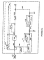
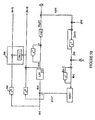
- the frequency locked loop tracker of the present invention including a phase-locked loop for more feedback control.
- a phase-locked loop is provided for locking to the phase of the demodulated and filtered signal u [n] described in conjunction with the first embodiment above.
- the frequency of a target signal is tracked but the phase is not.
- phase lock as well as frequency lock may be attained.
- the extra phase information provides for better isolation of the target signal for subtractive analysis.
- the pitch tracker is more sensitive to noise and phase locking is difficult to attain in rapidly changing signals.
- the analysis begins by demodulating a complex input signal z [n] 102 via multiplier 104 by a frequency warping signal 106 resulting in the complex demodulated signal d[n].
- the complex demodulated signal d[n] is coupled to a low pass filter 108 producing an analytic output u[n].
- the analytic signal u[n] is used in achieving phase lock by adding a modification to the frequency lock method described in the preferred embodiment.
- the phase lock loop is created by providing a second loop for tracking the phase mismatch error between the frequency warping signal 106 and the input signal z [n] 102. This is accomplished by taking the argument 202 of the analytic signal u[n] which yields a phase error.
- the resultant phase error is attenuated by a phase gain signal g ⁇ [n] via multiplier 204.
- the resultant attenuated phase error signal is coupled to the phase accumulator 124 of the preferred embodiment. Internal to the phase accumulator 124, this attenuated phase error is combined via an internal integrator with the derived phase estimate for phase lock.
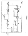
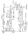
- the present invention is shown including a second frequency estimate f and ⁇ [n- ⁇ 1- ⁇ 2] for providing a frequency estimate including group delay compensation outside the "loop" for use in resynthesis or other means as is known in the art.
- the basic tracking loop is identical to that shown in Figure 1, however, a second frequency estimate is made outside of the loop based on the crude estimates of f and [n] from a first pass of a partial signal to be tracked along with the error estimation updates ⁇ f [n], The crude estimates are then refined using a Kay optimal phase-difference smoother.
- the estimated frequency f and [n] output from the integrator 120 is coupled via a delay line 304 to the frequency error signal ⁇ f [n] via adder 306. Since the new estimate is made outside the loop, the new estimate does not contribute to tracking dynamics.
- the group delay of the low pass filter 108 is taken into account by the delay line 304.
- the output of the adder 306, which is effectively the phase difference of the input signal if it had not been demodulated by the frequency warping signal 106, is then coupled to a Kay smoother 302 having a group delay of ⁇ 2.
- the Kay smoother 302 is simply an FIR filter with quadratic coefficients given by the formula for 1 ⁇ n ⁇ N-1.
- the Kay smoother output then reflects an improved estimate of the frequency being tracked. This improved estimate f and ⁇ [n- ⁇ 1- ⁇ 2] may be used in providing a resynthesized partial signal as will be described below.
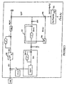
- the frequency locked loop tracker 100 of the preferred embodiment of the present invention is shown including a resynthesis module 401. Often it may be desired to produce a resynthesized partial signal p and[n] which is a cleaned up version of the partial signal p[n] being tracked from the input signal z [n].
- the cleaned up signal may be derived by combining the frequency warping signal 106 with the analytic signal u[n] via multiplier 402.
- the resultant output of this combination is an estimated partial signal p and[n] which reflects the combination of the estimated frequency from the integrator 120 (as embodied in the frequency warping signal 106) combined with the envelope signal u[n].
- this frequency locked loop tracker does not compensate for the group delay of the low pass filter 108.
- a better estimation of the partial signal p and[n- ⁇ 1 ] can be derived by providing a delay line 502 as shown in Figure 5A.
- the delay line 502 provides compensation for the group delay of the low pass filter and accordingly provides a more accurate resynthesized partial signal.
- the delay line 502 couples the frequency warping signal 106 to the multiplier 402 yielding an improved estimate that accounts for the group delay of the low pass filter.
- the partial signal p and[n] or p and[n- ⁇ 1 ] may be used in a notch-filter process to derive a notch-filtered output signal as shown in Figure 5B.
- the notch-filtered output signal is derived by subtracting the resynthesized partial signal p[n] from the input signal z[n].
- the input signal z[n] is coupled via a second delay line 504 to a first input of a subtractor 506.
- the second input of the subtractor 506 receives the resynthesized partial signal p and[n- ⁇ 1 ] from above.
- the subtractor 506 outputs a notch-filtered signal resulting from the subtraction of the partial signal from the input signal.
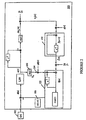
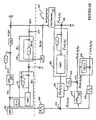
- FIG. 6A a second resynthesis module 601 for resynthesizing a partial signal is shown.
- the basic frequency locked loop tracker of Figure 1 is included with the Kay smoother filter of Figure 3 in order to make use of the improved frequency estimate f and ⁇ [n- ⁇ 1 - ⁇ 2 ] in producing a resynthesized partial signal.
- the improved frequency estimate f and ⁇ [n- ⁇ 1 - ⁇ 2 ] is scaled by combining it with a scaling signal (2 ⁇ / f s where f s is the sampling frequency) via multiplier 604.
- the scaled frequency is then coupled to a second phase accumulator 602 which integrates the scaled frequency to create an improved estimated phase of the demodulating phasor for the phase accumulator 602.
- the phase accumulator 602 outputs a second frequency warping signal 606 which is utilized in demodulating a delayed version of the input signal z n . This is accomplished by coupling the input signal z n via delay line 608 to multiplier 610 for combining with the second frequency warping signal 606.
- the complex demodulated signal d ⁇ [n- ⁇ 1 - ⁇ 2 ] is then coupled to a second low pass filter 612 having a group delay of ⁇ 3.
- the output of the second low pass filter 612 is coupled with the second frequency warping signal 606 via multiplier 614 in order to yield an improved partial signal p and ⁇ [n- ⁇ 1- ⁇ 2- ⁇ 3].
- the second low pass filter is the resynthesis filter, and is designed to allow for higher-quality filtering characterized by a narrower cut-off frequency and linear phase response.
- a delay line 616 may be used to couple the second frequency warping signal 606 to the multiplier 614 in order to account for the group delay of the second low pass filter 612.
- the resultant output of the combination of the delayed second frequency warping signal 606 and the analytic signal from the low pass filter 612 will result in an improved partial signal p and ⁇ [n- ⁇ 1 - ⁇ 2 - ⁇ 3 ]. Because this resynthesized signal is generated outside the normal tracking loop, no tracking dynamics will be affected by this resynthesis function. Those ordinarily skilled in the art will recognize that the more efficient estimate of the partial signal p and[n] can be used to calculate a high quality notched filter signal as is known in the art.
- the partial signal p and[n- ⁇ 1 - ⁇ 2 - ⁇ 3 ] may be used in a notch-filter process to derive a notch-filtered output signal as shown in Figure 6B.
- the notch-filtered output signal is derived by subtracting the resynthesized partial signal p[n] from the input signal z[n].
- the input signal z[n] is coupled via a fourth delay line 618 to a first input of a subtractor 620.
- the second input of the subtractor 620 receives the resynthesized partial signal p and[n- ⁇ 1 - ⁇ 2 - ⁇ 3 ] from above.
- the subtractor 620 outputs a notch-filtered signal resulting from the subtraction of the partial signal from the input signal.
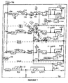
- a plurality of frequency locked loop trackers 700-1 to 700-N according to the preferred embodiment of the present invention are servoed in a harmonic locked loop tracker 701.
- the frequency locked loop tracker of the preferred embodiment of the present invention performs fast and accurate tracking of the instantaneous frequency of a single target partial signal in isolation. However if the signal to noise ratio is large, tracking may break down. Acoustical signals are often composed of complex mixtures of signals which bring the signal to noise ratio for a target partial signal down below the level needed for tracking according to the frequency locked loop method disclosed above. However, the harmonic structure of many natural acoustic signals allows for the robust tracking of the harmonic set of partials associated with a given harmonic signal.
- a harmonic locked loop tracker 701 wherein a plurality of frequency locked loop trackers are servoed to track a partial signal and a plurality of harmonics where each of the harmonics is a multiple of the fundamental frequency of the partial signal being tracked.
- an instantaneous frequency correction term is calculated for each harmonic.
- the harmonic signal s[n] is demodulated by the frequency warping signal 706 via multipliers 704 for each stage.
- Each stage further includes a low pass filter 708 which receives the complex demodulated signal d k [n] which in turn produces an analytic signal u k [n].
- This resultant signal u k [n] is then combined with a conjugate of itself delayed by one sample via multiplier 710 and delay element 712.
- the resultant output of the multiplier 710 is coupled to a phase extraction module 714 in order to calculate the phase difference of the resultant signal.
- the phase extraction module 714 is normalized by combining a normalization signal ( f s /2 ⁇ k where f s is the sampling frequency) via multiplier 716, resulting in a error term ⁇ (k) / f,o[n].
- the division by "k” takes into account that the kth stage is tracking "k" times the fundamental frequency.
- the resulting error signals ⁇ (k) / f,o[n] are combined for each stage to yield an overall optimized error correction for use by the frequency estimator and phase accumulator of the frequency locked loop tracker disclosed above.
- the frequency corrections from each tracker are weighted in accordance with the inverse of the variance of its tracking performance. Hence each harmonic of the tracked fundamental signal with a low variance will be weighted strongly, while harmonics with high variance (e.g., in noisy portions of the spectrum) will be weighted less strongly.
- the resultant fundamental frequency estimate is a minimum variance estimate, and is better than the best single frequency locked loop estimate.
- the error signal ⁇ (k) / f,o[n] is utilized in order to calculate a variance estimate for each of the individual phase trackers.
- the error signal ⁇ (k) / f,o[n] is multiplied by itself via squaring module 750.
- the output of the squaring module 750 is coupled to a variance estimator 752 utilized to calculate the variance of the error signal ⁇ (k) / f,o[n].
- the resultant variance estimate ⁇ 2 (k) / f,o[n] is inverted by module 754 and then coupled to a saturation detector 756.
- the saturation detector serves to compensate for signals with a high signal to noise ratio for the particular harmonic being tracked.
- the variance estimate becomes limited by the band width of the low pass filter 708 causing it to be too low.
- the variance estimate is saturated in this way, it causes the weighting for its associated tracker to be too high.
- This saturated variance estimate associated with the particular harmonic tracking stage then becomes an unreliable estimator of the true variance of the single target partial p[n] for this particular harmonic. This is especially a problem for higher harmonics where often a mix of broad band noise and audio signals occurs.
- the output of the saturation detector is combined via multiplier 757 with the individual error signal ⁇ (k) / f,o[n] to yield a weighted phase error signal.
- Each of the weighted error signals are combined by adders 758 and combined with the sum of the weights from each of the saturation detectors 756 for each harmonic phase tracker.
- the sum of the weights is inverted prior to combination with the sum of the phase error signals by inverter 760 in order to provide a normalizing factor for the summed phase error signal.
- the output of the multiplier 762 is the weighted phase error signal which is then combined with the tracker attenuation gain g 0 [n] and integrated to produce the estimated fundamental frequency f and o [n] for use in the demodulation of the input signal 702 as was described in accordance with the frequency locked loop tracker above.
- the input signal s[n] may include several voices, each comprising a fundamental partial signal and a set corresponding harmonics.
- the harmonics tracked by the set of parallel trackers in Figure 7 can be resynthesized so as to regenerate one complete "voice".
- such resynthesis is accomplished using one instance of the resynthesis module (i.e., multiplier 402) shown in Figure 4 for each of the trackers.
- Improved resynthesis is accomplished in a second preferred embodiment by providing one instance of the resynthesis module shown in Figure 5 or Figure 6 for each of the trackers in Figure 7.
- the harmonic loop tracker described in the preferred embodiment may also be used for tracking a well defined partial signal along with non-integer multiples of the fundamental frequency.
- This type of tracking known as inharmonic tracking is especially useful in tracking audio signals such as a piano, wherein sounds emanating from a piano are composed of stretched partials which are not integer multiples of a particular fundamental frequency.
- Inharmonic tracking is accomplished by defining a constant inharmonic ratio between the kth partial and the fundamental frequency. Such inharmonic frequency ratios may be supplied by a template or may be adaptively trained.
- the tracking of the inharmonic partials is the same with the exception that the kth demodulated signal must be computed explicitly, instead of in an iterative cascade, since the partials are no longer integer multiples of the fundamental frequency.
- the minimum-variance weighting method of the present invention could be used with a set of harmonically constrained peak detectors in an FFT-based pitch tracker.
Landscapes
- Engineering & Computer Science (AREA)
- Computational Linguistics (AREA)
- Signal Processing (AREA)
- Health & Medical Sciences (AREA)
- Audiology, Speech & Language Pathology (AREA)
- Human Computer Interaction (AREA)
- Physics & Mathematics (AREA)
- Acoustics & Sound (AREA)
- Multimedia (AREA)
- Stabilization Of Oscillater, Synchronisation, Frequency Synthesizers (AREA)
Claims (22)
- Frequenzstarre Grundfrequenz-Folgeschaltung zum Verfolgen eines Eingangssignals mit:wobei der Akkumulator einen Integrator (120) enthält, der das Frequenzfolge-Fehlersignal empfängt und die geschätzte Eingangssignalfrequenz erzeugt, und einen an den Integrator angeschlossenen (302, 304, 306) Frequenzglättungsfilter, der das Ausgangssignal des Integrators empfängt und dadurch die ausgegebene geschätzte Eingangssignalfrequenz verbessert.einer Demodulationseinrichtung (104) mit einem Demodulationssignal zum Demodulieren des Eingangssignals zu einem komplexen demodulierten Signal, einem Tiefpassfilter (108), der das komplexe demodulierte Signal empfängt und ein gefiltertes analytisches Signal erzeugt,einer Einrichtung (110, 112, 114, 116) zum Erfassen der Rate der Phasenänderung des gefilterten analytischen Signals und zum Erzeugen eines Frequenzfolge-Fehlersignals,einem Akkumulator (120) zum Empfangen des Frequenzfolge-Fehlersignals undAusgeben einer geschätzten Eingangssignalfrequenz undeiner Einrichtung (124) zum Aktualisieren des Demodulationssignals entsprechend der geschätzten Eingangssignalfrequenz,
- Grundfrequenz-Folgeschaltung nach Anspruch 1, wobei die Demodulationseinrichtung einen Multiplizierer zum Multiplizieren des Eingangssignals mit dem komplexen Konjugat eines Frequenzverschiebungssignals.
- Grundfrequenz-Folgeschaltung nach Anspruch 1 oder 2, ferner mit einer Einrichtung zum Subtrahieren eines resynthetisierten partiellen Signals aus dem Eingangssignal,
wobei die Subtrahiereinrichtung enthält:einen Resynthetisierer zum Resynthetisieren eines partiellen Signals aus dem gefilterten analytischen Signal und dem Demodulationssignal undeine Subtrahiereinrichtung zum Subtrahieren des resynthetisierten partiellen Signals vom Eingangssignal. - Grundfrequenz-Folgeschaltung nach Anspruch 1 oder 2, ferner mit einem Resynthetisierer mit einer Multipliziereinrichtung zum Kombinieren des Demodulationssignals mit dem gefilterten analytischen Signal zu einem resynthetisierten einzelnen partiellen Zielsignal.
- Grundfrequenz-Folgeschaltung nach Anspruch 4, ferner mit einer Subtrahiervorrichtung zum Entfernen des resynthetisierten einzelnen partiellen Zielsignals vom Eingangssignal, wobei die Subtrahiervorrichtung enthält:eine Verzögerungsleitung zum Kompensieren der Gruppenverzögerung im Tiefpassfilter, so dass ein verzögertes Eingangssignal entsteht undeine Subtrahiereinrichtung mit einem ersten und einem zweiten Eingang und einem Subtraktionsausgang, wobei dem ersten Eingang das verzögerte Eingangssignal unddem zweiten Eingang das resynthetisierte einzelne partielle Zielsignal zugeführt wird, so dass die Subtraktionseinrichtung ein Restsignal an ihrem Ausgang erzeugt, indem das resynthetisierte einzelne partielle Zielsignal vom verzögerten Eingangssignal entfernt wird.
- Grundfrequenz-Folgeschaltung nach Anspruch 5, wobei der Resynthetisierer enthält:eine zweite Demodulationseinrichtung mit einem zweiten Demodulationssignal, die auf das verbesserte Frequenzschätzungssignal anspricht und ein zweites komplexes Demoduliersignal erzeugt,eine zweite Verzögerungsleitung zum Anpassen der Gruppenverzögerungen des Tiefpassfilters und eines KAY-Filters, wobei die zweite Verzögerungsleitung das Eingangssignal auf die zweite Demodulationseinrichtung führt,einen zweiten Tiefpassfilter, der das zweite komplexe demodulierte Signal empfängt und ein zweites gefiltertes analytisches Signal erzeugt,eine dritte Verzögerungsleitung, die das zweite Demodulationssignal empfängt undein verzögertes zweites Demodulationssignal erzeugt, dessen Verzögerung gleich der Gruppenverzögerung des zweiten Tiefpassfilters ist,eine Multipliziereinrichtung zum Kombinieren des verzögerten zweiten Demodulationssignals mit dem zweiten gefilterten analytischen Signal zum Erzeugen eines resynthetisierten einzelnen partiellen Zielsignals.
- Grundfrequenz-Folgeschaltung nach Anspruch 1 oder 2, ferner mit einer phasenstarren Folgeeinrichtung, die das gefilterte analytische Signal unter Verwendung einer komplexen Phasenerfassungsfunktion verarbeitet und ein Phasenfehlersignal erzeugt, das der Einrichtung zum Aktualisieren des Demodulationssignals zugeführt wird, so dass eine Phasenverriegelung erzielt wird.
- Frequenzstarres Grundfrequenz-Folgeverfahren zum Verfolgen eines Eingangssignals mit folgenden Schritten:wobei beim Ausgeben das Frequenzfolge-Fehlersignal integriert und die geschätzte Eingangssignalfrequenz erzeugt und das Ausgangssignal des Integrators mit einem Frequenz-Glättungsfilter gefiltert wird, um die geschätzte Eingangssignalfrequenz zu verbessern.Demodulieren des Eingangssignals mit einem Demodulationssignal zu einem komplexen demodulierten Signal,Filtern des komplexen demodulierten Signals mit einem Tiefpassfilter, der ein gefiltertes analytisches Signal erzeugt,Erfassen der Rate der Phasenänderung des gefilterten analytischen Signals zur Erzeugung eines Frequenzfolge-Fehlersignals,Ausgeben einer geschätzten Eingangssignalfrequenz auf das Frequenzfolge-Fehlersignal undAktualisieren des Demodulationssignals auf die geschätzte Eingangssignalfrequenz,
- Verfahren nach Anspruch 8, wobei der Demodulationsschritt das Multiplizieren des Eingangssignals mit einem komplexen Konjugat eines Frequenzverschiebungssignals umfasst.
- Verfahren nach Anspruch 8, wobei das komplexe demodulierte Signal mit dem gefilterten analytischen Signal kombiniert wird, so dass sich ein resynthetisiertes einzelnes partielles Zielsignal ergibt.
- Verfahren nach Anspruch 10, wobei das resynthetisierte partielle Signal vom Eingangssignal subtrahiert und ein Restsignal erzeugt wird.
- Verfahren nach Anspruch 11, wobei der Subtraktionsschritt umfasst:Erzeugen eines verzögerten Eingangssignals undEntfernen des resynthetisierten einzelnen partiellen Zielsignals vom verzögerten Eingangssignal, so dass das Restsignal erzeugt wird.
- Verfahren nach Anspruch 8, ferner mit folgenden Schritten:Kombinieren des Demodulationssignals mit dem gefilterten analytischen Signal zu einem resynthetisierten einzelnen partiellen Zielsignal,Erzeugen eines verzögerten Eingangssignals durch Verzögern des Eingangssignals so, dass die mit dem Filtrierschritt verbundene Signalverzögerung kompensiert wird undAbziehen des resynthetisierten einzelnen partiellen Signals vom verzögerten Eingangssignal zur Erzeugung eines Restsignals.
- Grundfrequenz-Folgeschaltung zum Verfolgen eines Eingangssignals durch Verfolgen einer Anzahl von Harmonischen in einer harmonischen Signaldarstellung des Eingangssignals mit
Einer gleichen Anzahl von Frequenz-Folgeschaltungen nach einem der Ansprüche 1 bis 7, wobei jede Frequenzfolgeschaltung auf ein geschätztes Frequenzsignal anspricht, eine der Harmonischen verfolgt und ein Frequenzfolge-Fehlersignal erzeugt, wobei die Frequenzfolgeschaltungen harmonisch beschränkt sind, so dass jede Frequenzfolgeschaltung ein entsprechendes ganzzahliges Vielfach einer Grundfrequenzkomponente des Eingangssignals verfolgt,
Einrichtungen zum Gewichten jedes Frequenzfolge-Fehlersignals von jedem der Frequenzfolgeschaltungen zum Erzeugen eines gewichteten Frequenzfolge-Fehlersignals und
einem Akkumulator zum Empfangen der gewichteten Frequenzfolge-Fehlersignale und Ausgeben eines aktualisierten geschätzten Frequenzsignals, so dass jeder der Frequenzfolgeschaltungen eine entsprechende der Harmonischen entsprechend dem aktualisierten Frequenzschätzungsignal verfolgt. - Grundfrequenz-Folgungsschaltung nach Anspruch 14, wobei jede der Frequenzfolgeschaltungen enthältwobei die Grundfrequenz-Folgeschaltung ferner eine Einrichtung zum Aktualisieren des Demodulationssignals auf die geschätzte Eingangssignalfrequenz enthält.eine Demodulationseinrichtung mit einem Demodulationssignal zum Demodulieren der einen Harmonischen zu einem komplexen demodulierten Signal,ein Tiefpassfilter, das das komplexe demodulierte Signal empfängt und ein gefiltertes analytisches Signal erzeugt undeine Einrichtung zum Erfassen der Rate der Phasenänderung des gefilterten analytischen Signals und Erzeugen eines Frequenzfolge-Fehlersignals
- Grundfrequenz-Folgeschaltung nach Anspruch 13 oder 14, wobei jede der Frequenzfolgeschaltungen ferner einen Veränderlichkeitsschätzer zum Berechnen der Veränderlichkeit des Frequenzfolge-Fehlersignals enthält und jedes der Frequenzfolge-Fehlersignale entsprechend der inversen Veränderlichkeit des jeweiligen Frequenzfolgefehlersignals gewichtet wird.
- Grundfrequenz-Folgeschaltung nach Anspruch 16, wobei der Veränderlichkeitsschätzer die Veränderlichkeit des Frequenzfolge-Fehlersignals entsprechend folgender Gleichung berechnet:
ε 2 k [n] die Veränderlichkeitsschätzung,
ε k [n] das Frequenzfolge-Fehlersignal für die k-te Harmonische und
g k [n] die Schaltungsverstärkung. - Grundfrequenz-Folgeschaltung nach Anspruch 16, wobei die Gewichtungseinrichtung ferner einen Sättigungsdetektor enthält, zum Begrenzen der Gewichtung jeglicher Frequenzschätzung infolge einer k-ten Folgeschaltung in Fällen, in denen sich die Veränderlichkeitsschätzung sättigt.
- Verfahren nach einem der Ansprüche 8 bis 13, ferner gekennzeichnet durch Verfolgen des Eingangssignals durch Verfolgen einer Anzahl von Harmonischen in einer harmonischen Signaldarstellung des Eingangssignals mit folgenden Schritten:a) Durchführen des Verfahren nach einem der Ansprüche 8 bis 13 unter Verwendung einer Anzahl von Frequenzfolgeschaltungen, die je das Eingangssignal mit einem Demodulationssignal demodulieren, zum Verfolgen einer der Harmonischen, wobei die Anzahl der Frequenzfolgeschaltungen harmonisch beschränkt ist, so dass jede Frequenzfolgeschaltung jeweils ein ganzzahliges Vielfaches einer Grundfrequenzkomponente des Eingangssignals verfolgt,b) Berechnen eines Frequenzfolge-Fehlersignals für jede der Harmonischen,c) Gewichten jedes Frequenzfolge-Fehlersignals von jedem der Anzahl von Frequenzfolgeschaltungen zum Erzeugen eines gewichteten Frequenzfolge-Fehlersignals,d) Ausgeben einer geschätzten Signalfrequenz auf das gewichtete Frequenzfolge-Fehlersignal unde) Aktualisieren des Demodulationssignals auf die geschätzte Eingangssignalfrequenz.
- Verfahren nach Anspruch 19 ferner mit den Schritten des Bestimmens der Veränderlichkeit des Frequenzfehler-Folgesignals für jede der Harmonischen und Bestimmen, wenn sich die Veränderlichkeitsschätzung sättigt,
wobei der Gewichtungsschritt die Begrenzung der Gewichtung jedes Frequenzfolge-Fehlersignals umfasst, dessen Veränderlichkeitsschätzung in die Sättigung geht. - Verfahren nach Anspruch 20, wobei der Schritt des Bestimmens der Veränderlichkeit des Frequenzfolge-Fehlersignals für jede Harmonische nach folgender Gleichung erfolgt:
ε2 k [n] die Veränderlichkeitsschätzung,
ε k [n] das Frequenzfolge-Fehlersignal für die k-te Harmonische und
g k [n] die Schaltverstärkung. - Verfahren nach Anspruch 19, wobei der Gewichtungsschritt umfasst:a) Gewichten jedes Frequenzfolge-Fehlersignals durch den reziproken Wert der für jedes der Frequenzfolge-Fehlersignale bestimmten Veränderlichkeit undb) Summieren aller gewichteten Frequenzfolge-Fehlersignale zu dem gewichteten Frequenzfolge-Fehlersignal.
Applications Claiming Priority (3)
| Application Number | Priority Date | Filing Date | Title |
|---|---|---|---|
| US08/369,804 US5812737A (en) | 1995-01-09 | 1995-01-09 | Harmonic and frequency-locked loop pitch tracker and sound separation system |
| US369804 | 1995-01-09 | ||
| PCT/US1996/000350 WO1996021926A1 (en) | 1995-01-09 | 1996-01-11 | A harmonic and frequency-locked loop pitch tracker and sound separation system |
Publications (3)
| Publication Number | Publication Date |
|---|---|
| EP0803116A1 EP0803116A1 (de) | 1997-10-29 |
| EP0803116A4 EP0803116A4 (de) | 1998-12-30 |
| EP0803116B1 true EP0803116B1 (de) | 2003-04-02 |
Family
ID=23456999
Family Applications (1)
| Application Number | Title | Priority Date | Filing Date |
|---|---|---|---|
| EP96902649A Expired - Lifetime EP0803116B1 (de) | 1995-01-09 | 1996-01-11 | Harmonische und frequenzstarre grundfrequenz-folgeschaltung sowie system zur trennung von geräuschen |
Country Status (5)
| Country | Link |
|---|---|
| US (1) | US5812737A (de) |
| EP (1) | EP0803116B1 (de) |
| JP (1) | JPH10512375A (de) |
| DE (1) | DE69627131T2 (de) |
| WO (1) | WO1996021926A1 (de) |
Families Citing this family (17)
| Publication number | Priority date | Publication date | Assignee | Title |
|---|---|---|---|---|
| GB9912577D0 (en) * | 1999-05-28 | 1999-07-28 | Mitel Corp | Method of detecting silence in a packetized voice stream |
| JP3417880B2 (ja) * | 1999-07-07 | 2003-06-16 | 科学技術振興事業団 | 音源情報の抽出方法及び装置 |
| US6751564B2 (en) | 2002-05-28 | 2004-06-15 | David I. Dunthorn | Waveform analysis |
| US20060149539A1 (en) * | 2002-11-27 | 2006-07-06 | Koninklijke Philips Electronics N.V. | Method for separating a sound frame into sinusoidal components and residual noise |
| US7126876B1 (en) * | 2005-07-15 | 2006-10-24 | The United States Of America As Represented By The Secretary Of The Navy | Harmonic ambiguity resolver and inter array harmonic tracker |
| DE102007006084A1 (de) | 2007-02-07 | 2008-09-25 | Jacob, Christian E., Dr. Ing. | Verfahren zum zeitnahen Ermitteln der Kennwerte, Harmonischen und Nichtharmonischen von schnell veränderlichen Signalen mit zusätzlicher Ausgabe davon abgeleiteter Muster, Steuersignale, Ereignisstempel für die Nachverarbeitung sowie einer Gewichtung der Ergebnisse |
| KR101924192B1 (ko) * | 2009-05-19 | 2018-11-30 | 한국전자통신연구원 | 계층형 정현파 코딩을 이용한 오디오 신호의 인코딩 및 디코딩 방법 및 장치 |
| CN103383412B (zh) * | 2013-07-10 | 2015-08-26 | 珠海许继芝电网自动化有限公司 | 一种自适应软硬件频率跟踪采样的方法 |
| US9553620B2 (en) | 2014-07-16 | 2017-01-24 | Raytheon Company | Signal detection and characterization |
| US10411744B1 (en) | 2018-10-11 | 2019-09-10 | Ratheon Company | Waveform transformation and reconstruction |
| EP3657201B1 (de) * | 2018-11-20 | 2025-03-26 | NXP USA, Inc. | Phasenrotatorkalibrierung eines mehrkanaligen radar-senders |
| IT201900021111A1 (it) * | 2019-11-13 | 2021-05-13 | Consiglio Nazionale Ricerche | Circuito e metodo per modellare ed emulare la percezione del tono di suoni complessi |
| DE102021207339B3 (de) | 2021-07-12 | 2022-10-27 | Carl von Ossietzky Universität Oldenburg Körperschaft des öffentlichen Rechts | Verfahren und Vorrichtung zur Analyse eines Zeitsignals mit periodischen Signalanteilen sowie Computerprogrammprodukt und Computerprogramm |
| CN115825560B (zh) * | 2023-02-17 | 2023-05-23 | 青岛鼎信通讯股份有限公司 | 一种基于频率跟踪技术的低压电网智能核相方法 |
| CN116068452B (zh) * | 2023-03-08 | 2023-06-06 | 石家庄科林电气股份有限公司 | 基于电源特征的供电类别判断方法、双源电能计量方法及双源计量电能表 |
| CN117054737B (zh) * | 2023-08-15 | 2024-03-29 | 嘉兴市科讯电子有限公司 | 一种自相关滤波计算电力供电频率的方法和装置 |
| CN118817090B (zh) * | 2024-09-10 | 2024-12-10 | 中国工程物理研究院激光聚变研究中心 | 一种激光相位噪声欠采样测量方法、设备、介质及产品 |
Family Cites Families (11)
| Publication number | Priority date | Publication date | Assignee | Title |
|---|---|---|---|---|
| US3978287A (en) * | 1974-12-11 | 1976-08-31 | Nasa | Real time analysis of voiced sounds |
| US4004096A (en) * | 1975-02-18 | 1977-01-18 | The United States Of America As Represented By The Secretary Of The Army | Process for extracting pitch information |
| US4495475A (en) * | 1982-01-08 | 1985-01-22 | Litton Systems, Inc. | Residual mode phase locked loop |
| NL8200959A (nl) * | 1982-03-09 | 1983-10-03 | Philips Nv | Fm-ontvanger voorzien van een frequentie gesleutelde lus. |
| US4486900A (en) * | 1982-03-30 | 1984-12-04 | At&T Bell Laboratories | Real time pitch detection by stream processing |
| JP2759646B2 (ja) * | 1985-03-18 | 1998-05-28 | マサチユ−セツツ インステイテユ−ト オブ テクノロジ− | 音響波形の処理 |
| US4890071A (en) * | 1988-10-26 | 1989-12-26 | Hewlett-Packard Company | Signal generator utilizing a combined phase locked and frequency locked loop |
| US5157623A (en) * | 1989-12-30 | 1992-10-20 | Casio Computer Co., Ltd. | Digital filter with dynamically variable filter characteristics |
| JP2611557B2 (ja) * | 1991-02-19 | 1997-05-21 | 日本電気株式会社 | 判定帰還形自動等化器 |
| JPH0573093A (ja) * | 1991-09-17 | 1993-03-26 | Nippon Telegr & Teleph Corp <Ntt> | 信号特徴点の抽出方法 |
| US5353372A (en) * | 1992-01-27 | 1994-10-04 | The Board Of Trustees Of The Leland Stanford Junior University | Accurate pitch measurement and tracking system and method |
-
1995
- 1995-01-09 US US08/369,804 patent/US5812737A/en not_active Expired - Fee Related
-
1996
- 1996-01-11 WO PCT/US1996/000350 patent/WO1996021926A1/en not_active Ceased
- 1996-01-11 EP EP96902649A patent/EP0803116B1/de not_active Expired - Lifetime
- 1996-01-11 DE DE69627131T patent/DE69627131T2/de not_active Expired - Fee Related
- 1996-01-11 JP JP8521800A patent/JPH10512375A/ja not_active Ceased
Also Published As
| Publication number | Publication date |
|---|---|
| EP0803116A4 (de) | 1998-12-30 |
| DE69627131D1 (de) | 2003-05-08 |
| JPH10512375A (ja) | 1998-11-24 |
| DE69627131T2 (de) | 2004-02-05 |
| WO1996021926A1 (en) | 1996-07-18 |
| US5812737A (en) | 1998-09-22 |
| EP0803116A1 (de) | 1997-10-29 |
Similar Documents
| Publication | Publication Date | Title |
|---|---|---|
| EP0803116B1 (de) | Harmonische und frequenzstarre grundfrequenz-folgeschaltung sowie system zur trennung von geräuschen | |
| Gkiokas et al. | Music tempo estimation and beat tracking by applying source separation and metrical relations | |
| US7660718B2 (en) | Pitch detection of speech signals | |
| EP0809842B1 (de) | Adaptiver sprachsignalfilter | |
| CN102027533B (zh) | 用于确定音频信号的频谱的重力频率的多个局部中心的设备和方法 | |
| US5619004A (en) | Method and device for determining the primary pitch of a music signal | |
| US20100232624A1 (en) | Method and System for Virtual Bass Enhancement | |
| US9026435B2 (en) | Method for estimating a fundamental frequency of a speech signal | |
| EP0619041A1 (de) | Sprachinformationsextraktor | |
| Keiler et al. | Extracting sinusoids from harmonic signals | |
| CA2209916C (en) | A harmonic and frequency-locked loop pitch tracker and sound separation system | |
| Girin et al. | Comparing the order of a polynomial phase model for the synthesis of quasi-harmonic audio signals | |
| Argenti et al. | Automatic transcription of polyphonic music based on the constant-Q bispectral analysis | |
| Das et al. | Improved real-time monophonic pitch tracking with the extended complex Kalman filter | |
| Laurenti et al. | A nonlinear method for stochastic spectrum estimation in the modeling of musical sounds | |
| Böhler et al. | Monophonic pitch detection by evaluation of individually parameterized phase locked loops | |
| Gainza et al. | Harmonic sound source separation using FIR comb filters | |
| Hohmann | The Period-Modulated Harmonic Locked Loop (PM-HLL): A low-effort algorithm for rapid time-domain multi-periodicity estimation | |
| Pelle | A robust pitch extraction system based on phase locked loops | |
| EP4567785A1 (de) | Tonverschiebungsvorrichtung durch filterbank | |
| de Obaldía et al. | Improving Monophonic Pitch Detection Using the ACF and Simple Heuristics.” | |
| Marxer et al. | Low-latency bass separation using harmonic-percussion decomposition | |
| Pelle et al. | Pitch estimation using phase locked loops. | |
| Azarov et al. | Instantaneous harmonic analysis for vocal processing | |
| Fink et al. | TIME-DOMAIN CHROMA EXTRACTION |
Legal Events
| Date | Code | Title | Description |
|---|---|---|---|
| PUAI | Public reference made under article 153(3) epc to a published international application that has entered the european phase |
Free format text: ORIGINAL CODE: 0009012 |
|
| 17P | Request for examination filed |
Effective date: 19970722 |
|
| AK | Designated contracting states |
Kind code of ref document: A1 Designated state(s): DE FR GB |
|
| A4 | Supplementary search report drawn up and despatched |
Effective date: 19981118 |
|
| AK | Designated contracting states |
Kind code of ref document: A4 Designated state(s): DE FR GB |
|
| RIC1 | Information provided on ipc code assigned before grant |
Free format text: 7G 10L 11/04 A |
|
| GRAG | Despatch of communication of intention to grant |
Free format text: ORIGINAL CODE: EPIDOS AGRA |
|
| GRAG | Despatch of communication of intention to grant |
Free format text: ORIGINAL CODE: EPIDOS AGRA |
|
| 17Q | First examination report despatched |
Effective date: 20020516 |
|
| GRAG | Despatch of communication of intention to grant |
Free format text: ORIGINAL CODE: EPIDOS AGRA |
|
| GRAH | Despatch of communication of intention to grant a patent |
Free format text: ORIGINAL CODE: EPIDOS IGRA |
|
| GRAH | Despatch of communication of intention to grant a patent |
Free format text: ORIGINAL CODE: EPIDOS IGRA |
|
| GRAA | (expected) grant |
Free format text: ORIGINAL CODE: 0009210 |
|
| AK | Designated contracting states |
Designated state(s): DE FR GB |
|
| REG | Reference to a national code |
Ref country code: GB Ref legal event code: FG4D |
|
| REF | Corresponds to: |
Ref document number: 69627131 Country of ref document: DE Date of ref document: 20030508 Kind code of ref document: P |
|
| ET | Fr: translation filed | ||
| PLBE | No opposition filed within time limit |
Free format text: ORIGINAL CODE: 0009261 |
|
| STAA | Information on the status of an ep patent application or granted ep patent |
Free format text: STATUS: NO OPPOSITION FILED WITHIN TIME LIMIT |
|
| 26N | No opposition filed |
Effective date: 20040105 |
|
| PGFP | Annual fee paid to national office [announced via postgrant information from national office to epo] |
Ref country code: GB Payment date: 20070129 Year of fee payment: 12 |
|
| PGFP | Annual fee paid to national office [announced via postgrant information from national office to epo] |
Ref country code: DE Payment date: 20070314 Year of fee payment: 12 |
|
| PGFP | Annual fee paid to national office [announced via postgrant information from national office to epo] |
Ref country code: FR Payment date: 20070116 Year of fee payment: 12 |
|
| GBPC | Gb: european patent ceased through non-payment of renewal fee |
Effective date: 20080111 |
|
| PG25 | Lapsed in a contracting state [announced via postgrant information from national office to epo] |
Ref country code: DE Free format text: LAPSE BECAUSE OF NON-PAYMENT OF DUE FEES Effective date: 20080801 |
|
| REG | Reference to a national code |
Ref country code: FR Ref legal event code: ST Effective date: 20081029 |
|
| PG25 | Lapsed in a contracting state [announced via postgrant information from national office to epo] |
Ref country code: GB Free format text: LAPSE BECAUSE OF NON-PAYMENT OF DUE FEES Effective date: 20080111 |
|
| PG25 | Lapsed in a contracting state [announced via postgrant information from national office to epo] |
Ref country code: FR Free format text: LAPSE BECAUSE OF NON-PAYMENT OF DUE FEES Effective date: 20080131 |