EP0802772B1 - Haltevorrichtung für die wirbelsäule - Google Patents
Haltevorrichtung für die wirbelsäule Download PDFInfo
- Publication number
- EP0802772B1 EP0802772B1 EP96901378A EP96901378A EP0802772B1 EP 0802772 B1 EP0802772 B1 EP 0802772B1 EP 96901378 A EP96901378 A EP 96901378A EP 96901378 A EP96901378 A EP 96901378A EP 0802772 B1 EP0802772 B1 EP 0802772B1
- Authority
- EP
- European Patent Office
- Prior art keywords
- mounting part
- connecting rod
- housing
- implant
- spinal implant
- Prior art date
- Legal status (The legal status is an assumption and is not a legal conclusion. Google has not performed a legal analysis and makes no representation as to the accuracy of the status listed.)
- Expired - Lifetime
Links
- 239000007943 implant Substances 0.000 claims description 72
- 230000005489 elastic deformation Effects 0.000 claims description 4
- 210000002105 tongue Anatomy 0.000 claims 2
- 230000000903 blocking effect Effects 0.000 description 3
- 238000009434 installation Methods 0.000 description 3
- 238000005452 bending Methods 0.000 description 2
- 206010023509 Kyphosis Diseases 0.000 description 1
- 241000251539 Vertebrata <Metazoa> Species 0.000 description 1
- 201000008482 osteoarthritis Diseases 0.000 description 1
- 230000002093 peripheral effect Effects 0.000 description 1
- 230000000284 resting effect Effects 0.000 description 1
- 206010039722 scoliosis Diseases 0.000 description 1
- 206010041569 spinal fracture Diseases 0.000 description 1
- 238000001356 surgical procedure Methods 0.000 description 1
Images


Classifications
-
- A—HUMAN NECESSITIES
- A61—MEDICAL OR VETERINARY SCIENCE; HYGIENE
- A61B—DIAGNOSIS; SURGERY; IDENTIFICATION
- A61B17/00—Surgical instruments, devices or methods
- A61B17/56—Surgical instruments or methods for treatment of bones or joints; Devices specially adapted therefor
- A61B17/58—Surgical instruments or methods for treatment of bones or joints; Devices specially adapted therefor for osteosynthesis, e.g. bone plates, screws or setting implements
- A61B17/68—Internal fixation devices, including fasteners and spinal fixators, even if a part thereof projects from the skin
- A61B17/70—Spinal positioners or stabilisers, e.g. stabilisers comprising fluid filler in an implant
- A61B17/7001—Screws or hooks combined with longitudinal elements which do not contact vertebrae
- A61B17/7032—Screws or hooks with U-shaped head or back through which longitudinal rods pass
-
- A—HUMAN NECESSITIES
- A61—MEDICAL OR VETERINARY SCIENCE; HYGIENE
- A61B—DIAGNOSIS; SURGERY; IDENTIFICATION
- A61B17/00—Surgical instruments, devices or methods
- A61B17/56—Surgical instruments or methods for treatment of bones or joints; Devices specially adapted therefor
- A61B17/58—Surgical instruments or methods for treatment of bones or joints; Devices specially adapted therefor for osteosynthesis, e.g. bone plates, screws or setting implements
- A61B17/68—Internal fixation devices, including fasteners and spinal fixators, even if a part thereof projects from the skin
- A61B17/70—Spinal positioners or stabilisers, e.g. stabilisers comprising fluid filler in an implant
- A61B17/7074—Tools specially adapted for spinal fixation operations other than for bone removal or filler handling
- A61B17/7091—Tools specially adapted for spinal fixation operations other than for bone removal or filler handling for applying, tightening or removing longitudinal element-to-bone anchor locking elements, e.g. caps, set screws, nuts or wedges
-
- A—HUMAN NECESSITIES
- A61—MEDICAL OR VETERINARY SCIENCE; HYGIENE
- A61B—DIAGNOSIS; SURGERY; IDENTIFICATION
- A61B17/00—Surgical instruments, devices or methods
- A61B17/56—Surgical instruments or methods for treatment of bones or joints; Devices specially adapted therefor
- A61B17/58—Surgical instruments or methods for treatment of bones or joints; Devices specially adapted therefor for osteosynthesis, e.g. bone plates, screws or setting implements
- A61B17/68—Internal fixation devices, including fasteners and spinal fixators, even if a part thereof projects from the skin
- A61B17/70—Spinal positioners or stabilisers, e.g. stabilisers comprising fluid filler in an implant
- A61B17/7056—Hooks with specially-designed bone-contacting part
Definitions
- the present invention relates to a new type of spinal implant. More particularly, it relates to a spinal implant of the type which comprises means for fixing to a vertebra, a connecting rod, a mounting part extending on an axis XX ′ and comprising a housing open on the side opposite the fastening means and having opposite side openings for receiving a connecting rod extending transversely the axis XX ′ on either side of said mounting part to be secured with at least one spinal implant, a locking element intended to cooperate with said mounting part for block said connecting rod inside said housing and a ring intermediate of symmetrical shape of revolution around the axis XX '.
- the invention also relates to an assembly device for such an implant. spinal.
- the element of locking is a screw capable of being screwed into a thread provided in the housing of the mounting part of the spinal implant, in order to block the rod which is manually prepositioned in said housing.
- This type of implant assembled with a connecting rod is used to treat arthrosis, vertebral fractures or to correct deviations of the spine vertebral such as scoliosis or kyphosis.
- the surgeon generally fixes two implants per vertebra, then positions in each of the two implants a knurled rod, these two rods being parallel and previously bent according to the treatment and the correction to be made on the spine.
- the more or less curved knurled rod when the more or less curved knurled rod is positioned at inside the housing of the mounting part of this implant, it tends to go back up to exit the housing by blocking the access of the locking element to the housing thread. The surgeon must then press on said rod using the locking element while screwing it inside the housing, to force it to position itself in the housing and block it inside this last using the locking element. In some cases, when the stem has an accentuated bend, it may be that during the installation of the element of locking inside the housing of the implant mounting part, the latter breaks.
- an implant which includes a screw for attachment to a vertebra, a mounting platform that extends transverse to the axis of the fixing screw opposite it.
- the two walls between them define an open housing on the side opposite the screw fastening and having lateral openings for receiving a connecting rod extending along the axis of the mounting platform on either side of said housing.
- the implant also comprises an intermediate mounting element which includes an upper part in the form of a cylindrical sleeve provided with a internal thread into which a locking element is screwed to lock the rod of connection on the mounting platform.
- the intermediate mounting element has a lower part consisting of two side walls extending in direction of the fixing screw, and each carrying at their free end a tab of attachment provided with a tooth which extends in the circumferential direction of the part upper of said intermediate mounting element.
- the intermediate element of mounting is set up by rotation on the walls opposite the platform mounting, until its fixing lugs carrying the teeth come position under the mounting platform and cooperate with a concave housing provided under the latter. In the assembled position, the intermediate element of mounting does not rest on the connecting rod and does not block it in translation along the axis of said rod in its housing.
- the intermediate ring is a simple sleeve put in place by sliding on the mounting part simultaneously with the locking element which is screwed inside the part of mounting. When the locking element is fully screwed, the ring takes support on the connecting rod and locks it inside the housing of the part of mounting.
- the invention offers a new spinal implant that allows pre-tightening and pre-positioning of the rod inside the housing of the mounting part of the implant, which clears the part of the housing capable of receiving the element and allows easy installation of the locking element in said housing while keeping a minimum size of said implant.
- said ring intermediate is a pre-tightening ring intended to be positioned on the part of mounting before fitting the locking element, said ring pre-tightening intermediate cooperating with a snap with elastic deformation with the mounting part and coming to bear against said connecting rod for preposition the latter in said housing and facilitate the installation subsequent locking element in the latter regardless of the bending of said connecting rod.
- said intermediate pre-tightening ring is capable of being mounted on the surface external of said mounting part, and comprises two shaped support edges arch capable of resting on the connecting rod on either side of the part of mounting, when said ring is snapped onto said mounting portion.
- the intermediate pre-tightening ring having as axis of symmetry the axis XX ′, comprises on each side of each support edge in the form of an arch two slots which extend substantially parallel to the axis XX ′ and which confer at each bearing edge, flexibility in bearing on said connecting rod.
- the assembly device comprises a first clamp able to clamp between its branches the base of the mounting portion of said spinal implant and a second clamp comprising at one end a leg of general U shape able to be placed astride the connecting rod for the position next to the housing of the implant mounting part and a sleeve intended to support the intermediate pre-tightening ring and displaceable sliding on said tab to snap it with the mounting part of the implant and pre-position said connecting rod in the housing, the first clamp and the second clamp comprising each a stop, said stops being intended to come into mutual support during the assembly of the spinal implant with the connecting rod so as to take up the pushing forces exerted on the implant by the second clamp during the interlocking of the intermediate clamping ring with the mounting part of the implant.
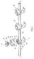
- FIG. 1 there is shown a spinal implant which includes means for fixing to a vertebra.
- these fixing means are constituted by a hook 10a able to hang on a vertebrate.
- these fixing means comprise a threaded rod making it possible to screw the spinal implant onto the vertebra.
- the spinal implant 10 comprises a part of mounting 11, the base of which is secured to the fixing hook 10a.
- This part of mounting 11 extends along a longitudinal axis XX ′, and has a general shape substantially cylindrical of revolution around this longitudinal axis XX ′.
- the mounting part 11 comprises a housing 12 provided with an opening situated on the side opposite the mounting hook 10a and two other opposite side openings of symmetrically about the axis XX '. Seen in section, as shown on Figures 2a to 2d, the housing 12 has a substantially U-shaped.
- the housing 12 is intended to receive a knurled connecting rod 20 bent or not, extending in a direction Y-Y 'transverse to the axis X-X', on either side of the part of fitting 11 to be secured here with two other spinal implants 10 '.
- the internal wall of the housing 12 is provided in the upper part near its opening located on the side opposite the fixing hook 10a, a thread 16 adapted to cooperate with a locking screw 13 comprising a thread 13a capable of being engaged in said housing in order to block the connecting rod 20 in the bottom of the housing 12.
- the spinal implant 10 includes an intermediate pre-tightening ring. 30 which has a symmetrical shape of revolution around the axis XX ′ and which is able to cooperate by snap-fastening with the mounting part 11 to come in press against the connecting rod 20 in order to pre-position it in the housing 12 (see figure 2b).
- this pre-tightening ring 30 has two edges support 31 formed in the peripheral lower edge of said ring and arranged opposite symmetrically to the axis XX '. These two bearing edges 31 have an arch shape and are capable of being supported as shown in the Figure 1 on the outer surface of the connecting rod 20, on either side of the part mounting 11, when the ring 30 is snapped onto the mounting part 11.
- This intermediate ring 30 is of course positioned on the mounting part 11 before the locking screw 13 is screwed inside the housing 12 to permanently lock the connecting rod 20 in the housing 12.
- This ring intermediate pre-tightening allows pre-positioning said rod 20 in the housing 12, by releasing the thread 16 from said housing 12 so as to facilitate the positioning of the locking element 13 in the housing 12.
- Such a structure offers many advantages in spine surgery and in particular makes it possible to greatly facilitate the operation of reducing a vertebra.
- the intermediate pre-tightening ring 30 has in its side wall two snap tabs 35, 36 positioned symmetrically with respect to the axis XX 'between the bearing edges 31 in the form ark.
- snap tabs 35.36 as shown more particularly Figure 1 extend in an arc. They are suitable for snap-fastening of the intermediate pre-tightening ring on the mounting part, to be deformed resiliently by cooperating with an annular flange 14 of the mounting part for come into abutment against this rim 14.
- the intermediate pre-tightening ring 30 comprises on either side of each arch-shaped bearing edge 31, slots 33, 32 extending parallel to the axis XX ′ and giving the latter flexibility of support.
- the slots 32,33 are positioned so substantially perpendicular to the outer surface of the connecting rod 20 for allow optimum support of each bearing edge 31 against the connecting rod 20.
- This positioning of the slots perpendicular to the external surface of the rod 20 is whatever the bending of the rod 20.
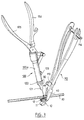
- This assembly device comprises a first clamp 110 provided with two branches 111,112 articulated around an axis (not shown here) and comprising actuating levers of said branches extending in the extension of each of the branches.
- the branches 111,112 are able to hold the base tight, the mounting part 11 of the implant 10.
- the first clamp 110 is provided with a blocking 14 with rack which makes it possible to block the clamp in a given position of tightening of said implant.
- the first clamp 110 has at the level of the articulation of said branches 111, 112 a stop 113.
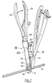
- the assembly apparatus comprises a second clamp 120 provided of a tubular body 120, and at one end of this body, a tab 121 of shape general U-shaped able to be placed astride the connecting rod 20 to position it in view of the housing 12 of the mounting part 11 (see FIG. 6).
- This second clamp 120 includes a sleeve 122 integral with a rod 130 mounted to slide inside the tubular body 120 and actuable using two levers 124,125 pivoting around an axis 126 and the lever 125 being connected to a system of connecting rods articulated 127,129, the connecting rod 129 being itself connected to said rod 130.
- This sleeve 122 is intended to support the intermediate pre-tightening ring 30. By through the rod 130 sliding inside the tubular body 120, the sleeve 122 is therefore movable by sliding on the tab 121 in the shape of a U.
- said second clamp 120 moves the rod 130 which causes it to slide on the tab 121 the sleeve 122 comprising the intermediate pre-tightening ring 30 of so that the pre-tightening ring comes to bear on the connecting rod 20 previously positioned opposite the housing 12 and the mounting part 11, then continuing to slide the sleeve 122 towards the part of mounting 10, the sleeve 122 snaps the pre-tightening ring 30 onto the part of mounting 11 by pre-positioning the knurled connecting rod 20 inside the housing 12. It should be noted that the engagement of the connecting rod 20 the interior of the housing 12 takes place simultaneously with the snap-fastening of the ring pre-tightening intermediate 30 on the mounting part 11 of the implant 10.
- the second clamp 120 has on the outer wall of its tubular body 120a a stop 123.
- This stop 123 is intended to come into abutment against the stop 113 of the first clamp 110 during the assembly of the implant 10 with the connecting rod 20 (see Figures 6 and 7) so that these stops 113, 123 resume the thrust forces exerted on the implant 10 by the second clamp 120 during the latching of the intermediate ring of tightening 30 with the mounting part 11 of the implant 10.
- the pre-tightening ring is mounted in the housing of the mounting part the implant, the locking screw then screwing onto the mounting part to press said pre-tightening ring into the housing and thus lock the rod liaison.
Landscapes
- Health & Medical Sciences (AREA)
- Orthopedic Medicine & Surgery (AREA)
- Neurology (AREA)
- Life Sciences & Earth Sciences (AREA)
- Surgery (AREA)
- Heart & Thoracic Surgery (AREA)
- Engineering & Computer Science (AREA)
- Biomedical Technology (AREA)
- Nuclear Medicine, Radiotherapy & Molecular Imaging (AREA)
- Medical Informatics (AREA)
- Molecular Biology (AREA)
- Animal Behavior & Ethology (AREA)
- General Health & Medical Sciences (AREA)
- Public Health (AREA)
- Veterinary Medicine (AREA)
- Prostheses (AREA)
- Surgical Instruments (AREA)
Claims (7)
- Haltevorrichtung (10) für die Wirbelsäule, welche Vorrichtung Mittel zur Befestigung an einem Wirbel umfaßt, einen Verbindungsstab (20), ein Montagestück (11), das sich in Richtung einer Achse X-X' erstreckt und einen Sitz (12) aufweist, der zu der den Befestigungsmitteln abgewandten Seite hin offen ist und einander gegenüberliegende seitliche Öffnungen zur Aufnahme des Verbindungsstabes (20) aufweist, der quer zu der Achse X-X' von einer Seite des genannten Montagestücks (11) zur anderen verläuft, um eine starre Verbindung mit mindestens einer weiteren Haltevorrichtung (10') für die Wirbelsäule herzustellen, ferner ein Verriegelungselement (13), das mit dem genannten Montagestück (11) zusammenwirken und den genannten Verbindungsstab (20) innerhalb des genannten Sitzes (12) blockieren soll, sowie einen bezüglich der Achse X-X' rotationssymmetrischen Zwischenring (30),
dadurch gekennzeichnet, daß der genannte Zwischenring (30) einen vorläufig fixierenden Ring bildet, der vor dem Anbringen des Verriegelungselements (13) auf das Montagestück (11) aufgesetzt werden soll, welcher vorläufig fixierende Zwischenring (30) durch Vermittlung eines elastisch verformbaren Rastelements mit dem Montagestück (11) zusammenwirkt und sich an den genannten Verbindungsstab (20) anlegt, um diesen in dem genannten Sitz (12) vorläufig zu fixieren und das Anbringen des Verriegelungselements (13) in diesem zu erleichtern, unabhängig von der Biegung des genannten Verbindungsstabes. - Haltevorrichtung (10) für die Wirbelsäule, nach Anspruch 1, dadurch gekennzeichnet, daß der genannte vorläufig fixierende Zwischenring (30), der auf die Außenfläche (15) des genannten Montagestücks (11) gesetzt werden kann, zwei bogenförmige Auflageränder (31) aufweist, die sich beiderseits des Montatgestücks (11) auf dem Verbindungsstab (20) abzustützen vermögen, wenn der genannte Ring (30) mit dem genannten Montageteil verrastet wird.
- Haltevorrichtung (10) für die Wirbelsäule, nach Anspruch 2, dadurch gekennzeichnet, daß der die Achse X-X' als Symmetrieachse aufweisende vorläufig fixierende Zwischenring (30) beiderseits jeder bogenförmigen Stützkante (31) jeweils einen von zwei im wesentlichen parallel zu der Achse X-X' verlaufenden Schlitzen (32,33) aufweist, die jeder Stützkante (31) eine nachgiebige Abstützung auf dem genannten Verbindungsstab (20) ermöglichen.
- Haltevorrichtung (10) für die Wirbelsäule, nach Anspruch 3, dadurch gekennzeichnet, daß die genannten Schlitze (32,33), die auf jeweils einer Seite jeder Stützkante (31) vorgesehen sind, sich beim Einrasten des genannten vorläufig flxierenden Zwischcnringes (30) an dem genannten Montagestück (11) im wesentlichen senkrecht zu der Außenfläche des Verbindungsstabes (20) einstellen können, um eine optimale Auflage jeder bogenförmigen Stützkante (31) auf dem genannten Verbindungsstab (20) zu ermöglichen.
- Haltevorrichtung (10) für die Wirbelsäule, nach einem der Ansprüche 1 bis 4, dadurch gekennzeichnet, daß an dem vorläufig fixierenden Zwischenring (30) zwei einrastende Zungen (35,36) ausgebildet sind, die symmetrisch zu der Achse X-X' zwischen den genannten Stützkanten (31) angeordnet sind, welche beiden einrastenden Zungen (35,36) sich bei der Anbringung des vorläufig fixierenden Zwischenringes (30) auf dem Montagestück (11) der Haltevorrichtung (10) elastisch zu verformen vermögen und sich gegen eine an dem Montagestück (11) vorgesehenen Kante (14) legen.
- Haltevorrichtung (10) für die Wirbelsäule, nach einem der Ansprüche 2 bis 5, dadurch gekennzeichnet, daß der Sitz (12) des genannten Montagestücks (11) im oberen Abschnitt mit einem Innengewinde (16) versehen ist, das mit dem mit Außengewinde versehenen, in den genannten Sitz (12) zu schraubenden Verriegelungselement (13) zusammenwirken soll, wobei der vorläufig fixierendo Ring (30) dem genannten Verbindungsstab (20) in dem genannten Sitz (12) eine vorläufige Lage zu geben vermag, so daß das Innengewinde (16) für das Einschrauben des Verriegelungselements (13) freigehalten ist.
- Montageeinrichtung für eine Haltevorrichtung (10) für die Wirbelsäule, nach einem der Ansprüche 1 bis 6, dadurch gekennzeichnet, daß sie eine erste Zange (110) aufweist, die zwischen ihren Backen (111,112) den Fuß des Montagestücks (11) der genannten Haltevorrichtung (10) für die Wirbelsäule einzuspannen vermag, sowie eine zweite Zange (120), die an einem Ende eine insgesamt U-förmige Klaue (121) aufweist, die rittlings auf den Verbindungsstab (20) gesetzt werden kann, um diesen dem Sitz (12) des Montagestücks (11) der Haltevorrichtung (10) gegenüberzustellen, sowie eine Hülse (122), die auf der genannten Klaue (121) verschiebbar ist und dazu dient, den vorläufig fixierenden Zwischenring (30) zu halten, um diesen durch elastische Verformung mit dem Montagestück (11) der Haltevorrichtung (10) zu verrasten und den genannten Verbindungsstab (20) vorläufig in den Sitz (12) einzuführen, wobei die erste Zange (110) und die zweite Zange (120) jeweils einen Anschlag (113, 123) aufweisen, welche Anschläge (113,123) dazu vorgesehen sind, sich bei dem Zusammenbau der Haltevorrichtung (10) für die Wirbelsäule so aneinander abzustützen, daß die durch, die zweite Zange (120) bei dem Verrasten durch elastische Verformung des vorläufig fixierenden Zwischenringes (30) mit dem Montagestück (11) der Haltevorrichtung (10) auf die Haltevorrichtung (10) ausgeübten Druckkräfte aufgefangen werden.
Applications Claiming Priority (3)
| Application Number | Priority Date | Filing Date | Title |
|---|---|---|---|
| FR9500306A FR2729291B1 (fr) | 1995-01-12 | 1995-01-12 | Implant rachidien |
| FR9500306 | 1995-01-12 | ||
| PCT/FR1996/000046 WO1996021396A1 (fr) | 1995-01-12 | 1996-01-11 | Fixateur rachidien |
Publications (2)
| Publication Number | Publication Date |
|---|---|
| EP0802772A1 EP0802772A1 (de) | 1997-10-29 |
| EP0802772B1 true EP0802772B1 (de) | 1998-10-21 |
Family
ID=9475074
Family Applications (1)
| Application Number | Title | Priority Date | Filing Date |
|---|---|---|---|
| EP96901378A Expired - Lifetime EP0802772B1 (de) | 1995-01-12 | 1996-01-11 | Haltevorrichtung für die wirbelsäule |
Country Status (4)
| Country | Link |
|---|---|
| EP (1) | EP0802772B1 (de) |
| ES (1) | ES2125712T3 (de) |
| FR (1) | FR2729291B1 (de) |
| WO (1) | WO1996021396A1 (de) |
Cited By (1)
| Publication number | Priority date | Publication date | Assignee | Title |
|---|---|---|---|---|
| FR2896981A1 (fr) * | 2006-02-08 | 2007-08-10 | Prosteel Sas Soc Par Actions S | Implant rachidien prothetique de maintien d'une tige d'un systeme d'osteosynthese rachidienne posterieure. |
Families Citing this family (132)
| Publication number | Priority date | Publication date | Assignee | Title |
|---|---|---|---|---|
| FR2756481B1 (fr) * | 1996-12-03 | 1999-07-23 | Biomat | Dispositif de correction de deviation rachidienne |
| FR2780269B1 (fr) * | 1998-06-26 | 2003-10-17 | Euros Sa | Implant rachidien |
| FR2794962B1 (fr) * | 1999-06-15 | 2001-10-05 | Euros Sa | Implant rachidien a liaison laterale par voie anterieure |
| EP1064885A1 (de) * | 1999-07-02 | 2001-01-03 | Sulzer Orthopedics Ltd. | Haltevorrichtung für die Wirbelsäule |
| US6547789B1 (en) | 1999-07-02 | 2003-04-15 | Sulzer Orthopedics Ltd. | Holding apparatus for the spinal column |
| US7833250B2 (en) | 2004-11-10 | 2010-11-16 | Jackson Roger P | Polyaxial bone screw with helically wound capture connection |
| JP2004505745A (ja) * | 2000-08-24 | 2004-02-26 | ジンテーズ アクチエンゲゼルシャフト クール | 骨固定要素を縦ロッドに連結するための装置 |
| US6726689B2 (en) | 2002-09-06 | 2004-04-27 | Roger P. Jackson | Helical interlocking mating guide and advancement structure |
| US8377100B2 (en) | 2000-12-08 | 2013-02-19 | Roger P. Jackson | Closure for open-headed medical implant |
| US8292926B2 (en) | 2005-09-30 | 2012-10-23 | Jackson Roger P | Dynamic stabilization connecting member with elastic core and outer sleeve |
| US10729469B2 (en) | 2006-01-09 | 2020-08-04 | Roger P. Jackson | Flexible spinal stabilization assembly with spacer having off-axis core member |
| US8353932B2 (en) | 2005-09-30 | 2013-01-15 | Jackson Roger P | Polyaxial bone anchor assembly with one-piece closure, pressure insert and plastic elongate member |
| US10258382B2 (en) | 2007-01-18 | 2019-04-16 | Roger P. Jackson | Rod-cord dynamic connection assemblies with slidable bone anchor attachment members along the cord |
| US7862587B2 (en) | 2004-02-27 | 2011-01-04 | Jackson Roger P | Dynamic stabilization assemblies, tool set and method |
| FR2827758B1 (fr) | 2001-07-25 | 2004-07-16 | Spinevision Sa | Ancillaire pour systeme d'ostheosynthese rachidienne |
| NZ532765A (en) * | 2001-11-22 | 2005-04-29 | Synthes Ag | Device for joining a longitudinal support with a bone fixation means |
| US6660006B2 (en) * | 2002-04-17 | 2003-12-09 | Stryker Spine | Rod persuader |
| WO2006052796A2 (en) | 2004-11-10 | 2006-05-18 | Jackson Roger P | Helical guide and advancement flange with break-off extensions |
| US8876868B2 (en) | 2002-09-06 | 2014-11-04 | Roger P. Jackson | Helical guide and advancement flange with radially loaded lip |
| US8257402B2 (en) | 2002-09-06 | 2012-09-04 | Jackson Roger P | Closure for rod receiving orthopedic implant having left handed thread removal |
| US8282673B2 (en) | 2002-09-06 | 2012-10-09 | Jackson Roger P | Anti-splay medical implant closure with multi-surface removal aperture |
| ES2629625T3 (es) | 2002-10-30 | 2017-08-11 | Zimmer Spine, Inc. | Sistema de estabilización espinal por inserción |
| US9539012B2 (en) | 2002-10-30 | 2017-01-10 | Zimmer Spine, Inc. | Spinal stabilization systems with quick-connect sleeve assemblies for use in surgical procedures |
| FR2848808B1 (fr) * | 2002-12-23 | 2005-10-21 | Eurosurgical | Dispositif d'immobilisation d'une tige de liaison dans un element d'ancrage osseux d'un implant rachidien |
| FR2857577B1 (fr) * | 2003-07-17 | 2006-02-24 | Eurosurgical | Perfectionnements aux dispositifs d'immobilisation rachidien |
| US8328850B2 (en) * | 2002-12-23 | 2012-12-11 | Choice Spine, Lp | Device for immobilizing a connecting rod in an osseous anchoring element of a rachidian implant |
| US7887539B2 (en) | 2003-01-24 | 2011-02-15 | Depuy Spine, Inc. | Spinal rod approximators |
| US7988698B2 (en) | 2003-01-28 | 2011-08-02 | Depuy Spine, Inc. | Spinal rod approximator |
| US6716214B1 (en) | 2003-06-18 | 2004-04-06 | Roger P. Jackson | Polyaxial bone screw with spline capture connection |
| US8540753B2 (en) | 2003-04-09 | 2013-09-24 | Roger P. Jackson | Polyaxial bone screw with uploaded threaded shank and method of assembly and use |
| US7621918B2 (en) | 2004-11-23 | 2009-11-24 | Jackson Roger P | Spinal fixation tool set and method |
| US7377923B2 (en) | 2003-05-22 | 2008-05-27 | Alphatec Spine, Inc. | Variable angle spinal screw assembly |
| US8137386B2 (en) | 2003-08-28 | 2012-03-20 | Jackson Roger P | Polyaxial bone screw apparatus |
| US8814911B2 (en) | 2003-06-18 | 2014-08-26 | Roger P. Jackson | Polyaxial bone screw with cam connection and lock and release insert |
| US8926670B2 (en) | 2003-06-18 | 2015-01-06 | Roger P. Jackson | Polyaxial bone screw assembly |
| US8092500B2 (en) | 2007-05-01 | 2012-01-10 | Jackson Roger P | Dynamic stabilization connecting member with floating core, compression spacer and over-mold |
| US8398682B2 (en) | 2003-06-18 | 2013-03-19 | Roger P. Jackson | Polyaxial bone screw assembly |
| US7766915B2 (en) | 2004-02-27 | 2010-08-03 | Jackson Roger P | Dynamic fixation assemblies with inner core and outer coil-like member |
| US8377102B2 (en) | 2003-06-18 | 2013-02-19 | Roger P. Jackson | Polyaxial bone anchor with spline capture connection and lower pressure insert |
| US8257398B2 (en) | 2003-06-18 | 2012-09-04 | Jackson Roger P | Polyaxial bone screw with cam capture |
| US8366753B2 (en) | 2003-06-18 | 2013-02-05 | Jackson Roger P | Polyaxial bone screw assembly with fixed retaining structure |
| US7776067B2 (en) | 2005-05-27 | 2010-08-17 | Jackson Roger P | Polyaxial bone screw with shank articulation pressure insert and method |
| US7967850B2 (en) | 2003-06-18 | 2011-06-28 | Jackson Roger P | Polyaxial bone anchor with helical capture connection, insert and dual locking assembly |
| FR2859376B1 (fr) | 2003-09-04 | 2006-05-19 | Spine Next Sa | Implant rachidien |
| US7666188B2 (en) | 2003-12-16 | 2010-02-23 | Depuy Spine, Inc. | Methods and devices for spinal fixation element placement |
| US7179261B2 (en) | 2003-12-16 | 2007-02-20 | Depuy Spine, Inc. | Percutaneous access devices and bone anchor assemblies |
| US11419642B2 (en) | 2003-12-16 | 2022-08-23 | Medos International Sarl | Percutaneous access devices and bone anchor assemblies |
| US7527638B2 (en) | 2003-12-16 | 2009-05-05 | Depuy Spine, Inc. | Methods and devices for minimally invasive spinal fixation element placement |
| US7842044B2 (en) | 2003-12-17 | 2010-11-30 | Depuy Spine, Inc. | Instruments and methods for bone anchor engagement and spinal rod reduction |
| ATE441376T1 (de) | 2003-12-17 | 2009-09-15 | Depuy Spine Inc | Instrumente und verfahren für den knochenankereingriff und die wirbelstangenreduktion |
| FR2863861B1 (fr) * | 2003-12-23 | 2006-03-17 | Eurosurgical | Instrument chirurgical de type declipseuse pour implant rachidien. |
| WO2005063135A1 (fr) * | 2003-12-23 | 2005-07-14 | Eurosurgical | Instrument chirurgical de type declipseuse pour implant rachidien |
| US7160300B2 (en) | 2004-02-27 | 2007-01-09 | Jackson Roger P | Orthopedic implant rod reduction tool set and method |
| US11241261B2 (en) | 2005-09-30 | 2022-02-08 | Roger P Jackson | Apparatus and method for soft spinal stabilization using a tensionable cord and releasable end structure |
| US8152810B2 (en) | 2004-11-23 | 2012-04-10 | Jackson Roger P | Spinal fixation tool set and method |
| CA2555868C (en) | 2004-02-27 | 2011-09-06 | Roger P. Jackson | Orthopedic implant rod reduction tool set and method |
| US7547318B2 (en) | 2004-03-19 | 2009-06-16 | Depuy Spine, Inc. | Spinal fixation element and methods |
| US7491207B2 (en) | 2004-04-12 | 2009-02-17 | Synthes Usa, Llc | Rod persuader |
| AU2004326327A1 (en) | 2004-07-06 | 2007-03-08 | Synthes Gmbh | Spinal rod insertion instrument |
| US7651502B2 (en) | 2004-09-24 | 2010-01-26 | Jackson Roger P | Spinal fixation tool set and method for rod reduction and fastener insertion |
| US8926672B2 (en) | 2004-11-10 | 2015-01-06 | Roger P. Jackson | Splay control closure for open bone anchor |
| US9980753B2 (en) | 2009-06-15 | 2018-05-29 | Roger P Jackson | pivotal anchor with snap-in-place insert having rotation blocking extensions |
| US9168069B2 (en) | 2009-06-15 | 2015-10-27 | Roger P. Jackson | Polyaxial bone anchor with pop-on shank and winged insert with lower skirt for engaging a friction fit retainer |
| WO2006057837A1 (en) | 2004-11-23 | 2006-06-01 | Jackson Roger P | Spinal fixation tool attachment structure |
| US8308782B2 (en) | 2004-11-23 | 2012-11-13 | Jackson Roger P | Bone anchors with longitudinal connecting member engaging inserts and closures for fixation and optional angulation |
| US8444681B2 (en) | 2009-06-15 | 2013-05-21 | Roger P. Jackson | Polyaxial bone anchor with pop-on shank, friction fit retainer and winged insert |
| US7875065B2 (en) | 2004-11-23 | 2011-01-25 | Jackson Roger P | Polyaxial bone screw with multi-part shank retainer and pressure insert |
| US9216041B2 (en) | 2009-06-15 | 2015-12-22 | Roger P. Jackson | Spinal connecting members with tensioned cords and rigid sleeves for engaging compression inserts |
| US10076361B2 (en) | 2005-02-22 | 2018-09-18 | Roger P. Jackson | Polyaxial bone screw with spherical capture, compression and alignment and retention structures |
| US7901437B2 (en) | 2007-01-26 | 2011-03-08 | Jackson Roger P | Dynamic stabilization member with molded connection |
| US7951175B2 (en) | 2005-03-04 | 2011-05-31 | Depuy Spine, Inc. | Instruments and methods for manipulating a vertebra |
| US7951172B2 (en) | 2005-03-04 | 2011-05-31 | Depuy Spine Sarl | Constrained motion bone screw assembly |
| US20060293692A1 (en) | 2005-06-02 | 2006-12-28 | Whipple Dale E | Instruments and methods for manipulating a spinal fixation element |
| US8105368B2 (en) | 2005-09-30 | 2012-01-31 | Jackson Roger P | Dynamic stabilization connecting member with slitted core and outer sleeve |
| US7918857B2 (en) | 2006-09-26 | 2011-04-05 | Depuy Spine, Inc. | Minimally invasive bone anchor extensions |
| CA2670988C (en) | 2006-12-08 | 2014-03-25 | Roger P. Jackson | Tool system for dynamic spinal implants |
| US8366745B2 (en) | 2007-05-01 | 2013-02-05 | Jackson Roger P | Dynamic stabilization assembly having pre-compressed spacers with differential displacements |
| US8475498B2 (en) | 2007-01-18 | 2013-07-02 | Roger P. Jackson | Dynamic stabilization connecting member with cord connection |
| US8012177B2 (en) | 2007-02-12 | 2011-09-06 | Jackson Roger P | Dynamic stabilization assembly with frusto-conical connection |
| US8172847B2 (en) | 2007-03-29 | 2012-05-08 | Depuy Spine, Inc. | In-line rod reduction device and methods |
| US10383660B2 (en) | 2007-05-01 | 2019-08-20 | Roger P. Jackson | Soft stabilization assemblies with pretensioned cords |
| US8979904B2 (en) | 2007-05-01 | 2015-03-17 | Roger P Jackson | Connecting member with tensioned cord, low profile rigid sleeve and spacer with torsion control |
| US8197518B2 (en) | 2007-05-16 | 2012-06-12 | Ortho Innovations, Llc | Thread-thru polyaxial pedicle screw system |
| US7942909B2 (en) | 2009-08-13 | 2011-05-17 | Ortho Innovations, Llc | Thread-thru polyaxial pedicle screw system |
| US7942910B2 (en) | 2007-05-16 | 2011-05-17 | Ortho Innovations, Llc | Polyaxial bone screw |
| US7947065B2 (en) | 2008-11-14 | 2011-05-24 | Ortho Innovations, Llc | Locking polyaxial ball and socket fastener |
| US7951173B2 (en) | 2007-05-16 | 2011-05-31 | Ortho Innovations, Llc | Pedicle screw implant system |
| US7942911B2 (en) | 2007-05-16 | 2011-05-17 | Ortho Innovations, Llc | Polyaxial bone screw |
| EP2160158A4 (de) | 2007-05-31 | 2013-06-26 | Roger P Jackson | Dynamisches stabilisationsverbindungselement mit vorgespanntem festen kern |
| US20090030420A1 (en) | 2007-07-26 | 2009-01-29 | Depuy Spine, Inc. | Spinal rod reduction instruments and methods for use |
| US8790348B2 (en) | 2007-09-28 | 2014-07-29 | Depuy Spine, Inc. | Dual pivot instrument for reduction of a fixation element and method of use |
| US8911477B2 (en) | 2007-10-23 | 2014-12-16 | Roger P. Jackson | Dynamic stabilization member with end plate support and cable core extension |
| US8608746B2 (en) | 2008-03-10 | 2013-12-17 | DePuy Synthes Products, LLC | Derotation instrument with reduction functionality |
| US8709015B2 (en) | 2008-03-10 | 2014-04-29 | DePuy Synthes Products, LLC | Bilateral vertebral body derotation system |
| US8025678B2 (en) | 2008-03-26 | 2011-09-27 | Depuy Spine, Inc. | Interspinous process spacer having tight access offset hooks |
| US8313512B2 (en) | 2008-03-26 | 2012-11-20 | Depuy Spine, Inc. | S-shaped interspinous process spacer having tight access offset hooks |
| US10973556B2 (en) | 2008-06-17 | 2021-04-13 | DePuy Synthes Products, Inc. | Adjustable implant assembly |
| EP2442739A1 (de) | 2008-08-01 | 2012-04-25 | Jackson, Roger P. | Langes verbindungselement mit ummantelten spannseilen |
| US8075603B2 (en) | 2008-11-14 | 2011-12-13 | Ortho Innovations, Llc | Locking polyaxial ball and socket fastener |
| US8206394B2 (en) | 2009-05-13 | 2012-06-26 | Depuy Spine, Inc. | Torque limited instrument for manipulating a spinal rod relative to a bone anchor |
| US11229457B2 (en) | 2009-06-15 | 2022-01-25 | Roger P. Jackson | Pivotal bone anchor assembly with insert tool deployment |
| US8998959B2 (en) | 2009-06-15 | 2015-04-07 | Roger P Jackson | Polyaxial bone anchors with pop-on shank, fully constrained friction fit retainer and lock and release insert |
| CN103826560A (zh) | 2009-06-15 | 2014-05-28 | 罗杰.P.杰克逊 | 具有套接杆和带摩擦配合压缩套爪的带翼插件的多轴骨锚 |
| US9668771B2 (en) | 2009-06-15 | 2017-06-06 | Roger P Jackson | Soft stabilization assemblies with off-set connector |
| CA2774471A1 (en) | 2009-10-05 | 2011-04-14 | James L. Surber | Polyaxial bone anchor with non-pivotable retainer and pop-on shank, some with friction fit |
| US8246656B2 (en) | 2010-02-25 | 2012-08-21 | Depuy Spine, Inc. | Crossover spinous process implant |
| US12383311B2 (en) | 2010-05-14 | 2025-08-12 | Roger P. Jackson | Pivotal bone anchor assembly and method for use thereof |
| WO2012030712A1 (en) | 2010-08-30 | 2012-03-08 | Zimmer Spine, Inc. | Polyaxial pedicle screw |
| JP2013540468A (ja) | 2010-09-08 | 2013-11-07 | ロジャー・ピー・ジャクソン | 弾性部および非弾性部を有する動的固定化部材 |
| DE112011104028A1 (de) | 2010-11-02 | 2013-12-12 | Roger P. Jackson | Polyaxialer Knochenanker mit Schnellsteck-Schaft und drehbarer Halterung |
| WO2012128825A1 (en) | 2011-03-24 | 2012-09-27 | Jackson Roger P | Polyaxial bone anchor with compound articulation and pop-on shank |
| US8911479B2 (en) | 2012-01-10 | 2014-12-16 | Roger P. Jackson | Multi-start closures for open implants |
| US8911478B2 (en) | 2012-11-21 | 2014-12-16 | Roger P. Jackson | Splay control closure for open bone anchor |
| US10058354B2 (en) | 2013-01-28 | 2018-08-28 | Roger P. Jackson | Pivotal bone anchor assembly with frictional shank head seating surfaces |
| US8852239B2 (en) | 2013-02-15 | 2014-10-07 | Roger P Jackson | Sagittal angle screw with integral shank and receiver |
| US9486256B1 (en) | 2013-03-15 | 2016-11-08 | Nuvasive, Inc. | Rod reduction assemblies and related methods |
| US10136927B1 (en) | 2013-03-15 | 2018-11-27 | Nuvasive, Inc. | Rod reduction assemblies and related methods |
| DE102013107498A1 (de) * | 2013-03-22 | 2014-09-25 | Aesculap Ag | Wirbelsäulenstabilisierungssystem und chirurgisches Befestigungselement für ein Wirbelsäulenstabilisierungssystem |
| US9453526B2 (en) | 2013-04-30 | 2016-09-27 | Degen Medical, Inc. | Bottom-loading anchor assembly |
| US9566092B2 (en) | 2013-10-29 | 2017-02-14 | Roger P. Jackson | Cervical bone anchor with collet retainer and outer locking sleeve |
| US9717533B2 (en) | 2013-12-12 | 2017-08-01 | Roger P. Jackson | Bone anchor closure pivot-splay control flange form guide and advancement structure |
| US9451993B2 (en) | 2014-01-09 | 2016-09-27 | Roger P. Jackson | Bi-radial pop-on cervical bone anchor |
| US20150230828A1 (en) | 2014-02-20 | 2015-08-20 | K2M, Inc. | Spinal fixation device |
| US9597119B2 (en) | 2014-06-04 | 2017-03-21 | Roger P. Jackson | Polyaxial bone anchor with polymer sleeve |
| US10064658B2 (en) | 2014-06-04 | 2018-09-04 | Roger P. Jackson | Polyaxial bone anchor with insert guides |
| US10966762B2 (en) | 2017-12-15 | 2021-04-06 | Medos International Sarl | Unilateral implant holders and related methods |
| US11051861B2 (en) | 2018-06-13 | 2021-07-06 | Nuvasive, Inc. | Rod reduction assemblies and related methods |
| US11291482B2 (en) | 2019-03-21 | 2022-04-05 | Medos International Sarl | Rod reducers and related methods |
| US11291481B2 (en) | 2019-03-21 | 2022-04-05 | Medos International Sarl | Rod reducers and related methods |
| USD1004774S1 (en) | 2019-03-21 | 2023-11-14 | Medos International Sarl | Kerrison rod reducer |
| EP4240262B1 (de) | 2020-11-09 | 2024-12-04 | Medos International Sàrl | Untersetzungsgetriebe für biplanare zange |
| WO2023089096A1 (en) | 2021-11-19 | 2023-05-25 | Medos International Sarl | Reducer locking mechanisms |
Family Cites Families (4)
| Publication number | Priority date | Publication date | Assignee | Title |
|---|---|---|---|---|
| GB9014817D0 (en) * | 1990-07-04 | 1990-08-22 | Mehdian Seyed M H | Improvements in or relating to apparatus for use in the treatment of spinal disorders |
| US5020519A (en) * | 1990-12-07 | 1991-06-04 | Zimmer, Inc. | Sagittal approximator |
| US5281222A (en) * | 1992-06-30 | 1994-01-25 | Zimmer, Inc. | Spinal implant system |
| DE9403231U1 (de) * | 1994-02-26 | 1994-04-21 | Aesculap Ag, 78532 Tuttlingen | Chirurgisches Implantat |
-
1995
- 1995-01-12 FR FR9500306A patent/FR2729291B1/fr not_active Expired - Fee Related
-
1996
- 1996-01-11 ES ES96901378T patent/ES2125712T3/es not_active Expired - Lifetime
- 1996-01-11 WO PCT/FR1996/000046 patent/WO1996021396A1/fr not_active Ceased
- 1996-01-11 EP EP96901378A patent/EP0802772B1/de not_active Expired - Lifetime
Cited By (1)
| Publication number | Priority date | Publication date | Assignee | Title |
|---|---|---|---|---|
| FR2896981A1 (fr) * | 2006-02-08 | 2007-08-10 | Prosteel Sas Soc Par Actions S | Implant rachidien prothetique de maintien d'une tige d'un systeme d'osteosynthese rachidienne posterieure. |
Also Published As
| Publication number | Publication date |
|---|---|
| FR2729291B1 (fr) | 1997-09-19 |
| WO1996021396A1 (fr) | 1996-07-18 |
| EP0802772A1 (de) | 1997-10-29 |
| FR2729291A1 (fr) | 1996-07-19 |
| ES2125712T3 (es) | 1999-03-01 |
Similar Documents
| Publication | Publication Date | Title |
|---|---|---|
| EP0802772B1 (de) | Haltevorrichtung für die wirbelsäule | |
| FR2780269A1 (fr) | Implant rachidien | |
| EP0984731B1 (de) | Haken für die osteosynthese der wirbelsäule | |
| EP0443892B1 (de) | Implantat für Osteosyntheseeinrichtung, insbesondere für die Wirbelsäule | |
| EP0971639B1 (de) | Vorrichtung zur wirbelsäulen-osteosythese mit versetzt angeordnetem zwischenwirbelverankerungsstab | |
| EP1575433B1 (de) | Fixierungssystem für knochenplatte | |
| CA2160910C (fr) | Implant pour dispositif d'osteosynthese, notamment du rachis | |
| EP1199993B1 (de) | Befestigungsvorrichtung und hilfsgerät zur stabilisierung der wirbel | |
| EP0932368B1 (de) | Osteosynthesesystem für wirbelarthrodese | |
| EP1339337B1 (de) | Vorrichtung zur befestigung einer stange und eines kugelsymmetrischen schraubenkopfs | |
| EP1011504B1 (de) | Vorrichtung zur osteosynthese die ein verbindungselement der wirbelsaülenstange und der verankerungselemente aufweist | |
| CA2377028A1 (fr) | Organe d'ancrage avec une bague de securite | |
| WO1999055247A1 (fr) | Systeme d'osteosynthese rachidienne avec moyens de serrage notamment pour une fixation anterieure | |
| FR2796545A1 (fr) | Liaison poly-axiale pour systeme d'osteosynthese, notamment pour le rachis | |
| WO2000076413A1 (fr) | Implant pour dispositif d'osteosynthese notamment du rachis | |
| EP1119305A1 (de) | Spinales osteosynthesesystem mit verbesserter stabilität | |
| WO1995014437A1 (fr) | Implant pour dispositif d'osteosynthese, notamment du rachis et instrument correspondant de pose | |
| EP0682918B1 (de) | Vorrichtung zur Wirbelsäulenosteosynthese | |
| EP1155662A1 (de) | Übertragungselement für Zahnprothesen | |
| EP0592266A1 (de) | Stabbefestigungsvorrichtung, insbesondere für Osteosynthese oder Arthrodese | |
| FR2794962A1 (fr) | Implant rachidien a liaison laterale par voie anterieure | |
| FR2747028A1 (fr) | Dispositif de fixation d'une tige d'osteosynthese rachidienne orientable a moyens de confirmation de blocage angulaire | |
| FR2736258A1 (fr) | Dispositif de fixation sur une tige d'un organe, en particulier pour une instrumentation d'orthopedie rachidienne |
Legal Events
| Date | Code | Title | Description |
|---|---|---|---|
| PUAI | Public reference made under article 153(3) epc to a published international application that has entered the european phase |
Free format text: ORIGINAL CODE: 0009012 |
|
| 17P | Request for examination filed |
Effective date: 19970804 |
|
| AK | Designated contracting states |
Kind code of ref document: A1 Designated state(s): ES FR IT |
|
| GRAG | Despatch of communication of intention to grant |
Free format text: ORIGINAL CODE: EPIDOS AGRA |
|
| 17Q | First examination report despatched |
Effective date: 19971210 |
|
| GRAG | Despatch of communication of intention to grant |
Free format text: ORIGINAL CODE: EPIDOS AGRA |
|
| GRAH | Despatch of communication of intention to grant a patent |
Free format text: ORIGINAL CODE: EPIDOS IGRA |
|
| GRAH | Despatch of communication of intention to grant a patent |
Free format text: ORIGINAL CODE: EPIDOS IGRA |
|
| GRAA | (expected) grant |
Free format text: ORIGINAL CODE: 0009210 |
|
| AK | Designated contracting states |
Kind code of ref document: B1 Designated state(s): ES FR IT |
|
| ITF | It: translation for a ep patent filed | ||
| REG | Reference to a national code |
Ref country code: ES Ref legal event code: FG2A Ref document number: 2125712 Country of ref document: ES Kind code of ref document: T3 |
|
| PLBE | No opposition filed within time limit |
Free format text: ORIGINAL CODE: 0009261 |
|
| STAA | Information on the status of an ep patent application or granted ep patent |
Free format text: STATUS: NO OPPOSITION FILED WITHIN TIME LIMIT |
|
| 26N | No opposition filed | ||
| PGFP | Annual fee paid to national office [announced via postgrant information from national office to epo] |
Ref country code: ES Payment date: 20041209 Year of fee payment: 10 |
|
| PGFP | Annual fee paid to national office [announced via postgrant information from national office to epo] |
Ref country code: FR Payment date: 20051024 Year of fee payment: 11 |
|
| PGFP | Annual fee paid to national office [announced via postgrant information from national office to epo] |
Ref country code: IT Payment date: 20060131 Year of fee payment: 11 |
|
| REG | Reference to a national code |
Ref country code: FR Ref legal event code: ST Effective date: 20070930 |
|
| REG | Reference to a national code |
Ref country code: ES Ref legal event code: FD2A Effective date: 20070112 |
|
| PG25 | Lapsed in a contracting state [announced via postgrant information from national office to epo] |
Ref country code: FR Free format text: LAPSE BECAUSE OF NON-PAYMENT OF DUE FEES Effective date: 20070131 |
|
| PG25 | Lapsed in a contracting state [announced via postgrant information from national office to epo] |
Ref country code: ES Free format text: LAPSE BECAUSE OF NON-PAYMENT OF DUE FEES Effective date: 20070112 |
|
| PG25 | Lapsed in a contracting state [announced via postgrant information from national office to epo] |
Ref country code: IT Free format text: LAPSE BECAUSE OF NON-PAYMENT OF DUE FEES Effective date: 20070111 |