EP0802650A2 - Méthode de multiplexage faisant preuve de robustesse contre les erreurs - Google Patents
Méthode de multiplexage faisant preuve de robustesse contre les erreurs Download PDFInfo
- Publication number
- EP0802650A2 EP0802650A2 EP97104733A EP97104733A EP0802650A2 EP 0802650 A2 EP0802650 A2 EP 0802650A2 EP 97104733 A EP97104733 A EP 97104733A EP 97104733 A EP97104733 A EP 97104733A EP 0802650 A2 EP0802650 A2 EP 0802650A2
- Authority
- EP
- European Patent Office
- Prior art keywords
- data
- header
- synchronization
- data blocks
- stations according
- Prior art date
- Legal status (The legal status is an assumption and is not a legal conclusion. Google has not performed a legal analysis and makes no representation as to the accuracy of the status listed.)
- Withdrawn
Links
Images

Classifications
-
- H—ELECTRICITY
- H04—ELECTRIC COMMUNICATION TECHNIQUE
- H04L—TRANSMISSION OF DIGITAL INFORMATION, e.g. TELEGRAPHIC COMMUNICATION
- H04L1/00—Arrangements for detecting or preventing errors in the information received
- H04L1/004—Arrangements for detecting or preventing errors in the information received by using forward error control
- H04L1/0056—Systems characterized by the type of code used
- H04L1/0057—Block codes
-
- H—ELECTRICITY
- H03—ELECTRONIC CIRCUITRY
- H03M—CODING; DECODING; CODE CONVERSION IN GENERAL
- H03M13/00—Coding, decoding or code conversion, for error detection or error correction; Coding theory basic assumptions; Coding bounds; Error probability evaluation methods; Channel models; Simulation or testing of codes
- H03M13/35—Unequal or adaptive error protection, e.g. by providing a different level of protection according to significance of source information or by adapting the coding according to the change of transmission channel characteristics
-
- H—ELECTRICITY
- H04—ELECTRIC COMMUNICATION TECHNIQUE
- H04J—MULTIPLEX COMMUNICATION
- H04J3/00—Time-division multiplex systems
- H04J3/02—Details
- H04J3/06—Synchronising arrangements
- H04J3/0602—Systems characterised by the synchronising information used
-
- H—ELECTRICITY
- H04—ELECTRIC COMMUNICATION TECHNIQUE
- H04L—TRANSMISSION OF DIGITAL INFORMATION, e.g. TELEGRAPHIC COMMUNICATION
- H04L7/00—Arrangements for synchronising receiver with transmitter
- H04L7/04—Speed or phase control by synchronisation signals
- H04L7/10—Arrangements for initial synchronisation
-
- H—ELECTRICITY
- H04—ELECTRIC COMMUNICATION TECHNIQUE
- H04N—PICTORIAL COMMUNICATION, e.g. TELEVISION
- H04N19/00—Methods or arrangements for coding, decoding, compressing or decompressing digital video signals
- H04N19/85—Methods or arrangements for coding, decoding, compressing or decompressing digital video signals using pre-processing or post-processing specially adapted for video compression
- H04N19/89—Methods or arrangements for coding, decoding, compressing or decompressing digital video signals using pre-processing or post-processing specially adapted for video compression involving methods or arrangements for detection of transmission errors at the decoder
Definitions
- the invention is based on a method for the transmission of data blocks according to the preamble of the main claim.
- the protocol H.22P (ITU-T Study Group 15, LBC 95-276 ITU-T Recommendation H.22P ")
- the frame structures, the formats of the data and control fields and a structure for the data to be transmitted by the multiplexer, the multiplex protocol are specified.
- the multiplex protocol enables the processing of logical information that reaches the multiplex level via the adaptation level into uniform data units.
- the protocol enables the transmission of any combination of digital audio and video data or other information via a data line and, in order to prevent data loss, proposes a special protocol which has a synchronization pattern with a length of 31 bits. He is the HEADER (31 or 63 bits) and the information field with fixed length adjusted.
- the synchronization pattern must be recognized by a correlation condition in the receiver; only then can the processing of the data blocks in the receiver begin. With this method, data loss can occur due to a loss of synchronization. In addition, there is no mechanism that fills fixed-length data blocks with data if the data source stops sending data.
- the inventive method with the characterizing features of claim 1 has the advantage that the synchronization is combined with an error detection method that detects errors in the transmission of the HEADER. This means that an error-free HEADER can be used to ensure synchronization.
- the start synchronization process which shows a very fast possibility of synchronization, is particularly advantageous.
- the start synchronization is advantageously carried out a number of times.
- a very good way of filling up the data is to feed synchronization words of the data source through the multiplexer.
- the signaling that fill bits have been used in the HEADER has a very favorable effect.
- the embodiment which extends error detection and error correction methods to the entire data block is also advantageous for secure transmission.
- the data transmission of any data signals takes place according to FIG. 1 over hierarchically structured levels.
- the signals some of which are analog, come from the individual data devices via the application level to the coding level.
- the contents of the logical channels LCN are passed on to the adaptation level of the multiplexer.
- the data are still forwarded to the multiplex level as MUX-SDUs (Service Data Units) in separate channels.
- MUX-SDUs Service Data Units
- This level processes the multitude of channels into one channel and outputs MUX PDUs (Protocol Data Units).
- MUX PDUs Service Data Units
- the first field SYNC contains a synchronization pattern of variable length, which contains a clearly detectable bit sequence of, for example, 31 bits.
- the synchronization pattern is placed in front of each multiplex packet.
- a pattern e.g. B. Barker or Williard sequences can be used.
- HEADER field you define the transfer scheme for the subsequent information block. An example of such a transmission scheme is described in protocol H.223 (ITU-T Study Group 15). Such a HEADER has 4 bits, for example. All 16 states that the HEADER can describe with the 4 bits are stored in a table.
- the information field follows. It is structured according to the rules defined in the HEADER for the various data sources. The information field is filled with data in accordance with the multiplex scheme specified by the HEADER until the packet length n is reached. A connection must be established as the first step for data transmission. For this purpose, the length n of the data blocks is determined using a control protocol. The length n can be set for the receiver and transmitter, even at a later time. To do this, the control protocol must intervene in the transmission and carry out a comparison.
- a particularly simple and fail-safe synchronization can be achieved by using a synchronization pattern (SYNC) is always searched for at the end of a data block.
- SYNC synchronization pattern
- this synchronization strategy means that a subsequent synchronization pattern cannot be recognized since it is not in the correct time window.
- the synchronization of the first data block, the start synchronization is therefore of particular importance and it must be ensured that this start synchronization takes place with particular certainty.
- a start synchronization can only take place if both synchronization patterns and an error-free HEADER are found.
- a certain number of incorrect synchronization patterns or HEADERS can then be accepted for the synchronization of the subsequent data blocks (MUX-PDUs) without the synchronization being lost as a result. It is when establishing a connection and the start synchronization z. B. advantageous to use shorter lengths for n at the beginning of the transmission (connection establishment with the help of a control protocol). With the help of the control protocol, a point in time is then defined from which the length n is changed.
- a minimum number of bits is specified which must match between a pattern in the data stream and the synchronization pattern defined by the control protocol. If this correlation minimum is reached (correlation condition), the synchronization pattern is considered to have been found. If on if a synchronization pattern has been found, an error detection procedure is carried out for the HEADER. The synchronization in the receiver is only successfully established if an error-free HEADER has been found for the synchronization pattern. In the simplest case, the error detection can be a parity check, but is preferably carried out using a CRC code. If an error was found in the transmission of the data, the synchronization process continues with the search for the next synchronization pattern. In this example, the SYNC and the associated error-free HEADER must be found once in order to initiate the start synchronization.
- the next synchronization pattern is searched for a complete frame of length n.
- a counter runs along, which is incremented if the synchronization pattern does not meet the correlation condition and the HEADER cannot be recognized without errors. If the counter has exceeded a limit value G2 (integer value that is determined by the control protocol), the synchronization is considered lost and it must be re-synchronized according to the above scheme. After four attempts, the synchronization is typically considered lost and a new start synchronization takes place. If the synchronization in the receiver has been successful, the processing of the HEADERS and the INFORMATION begins.
- the synchronization principle can therefore be expanded by not only finding the synchronization pattern and the associated error-free HEADER once, but G1 times (whole number to be set) before the synchronization is considered successful.
- a further advantageous embodiment varies the start synchronization, in that the synchronization pattern SYNC must be found for G1 successive multiplex packets and a free HEADER must be found for the last packet.
- a further embodiment is used in particular when there is insufficient information in the data source to fill the available space in the INFORMATION field.
- the so-called multiplex slot is known for each data source. If a data source stops its data transmission, it makes sense to change the HEADER and thus no longer provide the data source with space in the next information field. If residual data from the data source is still to be transmitted, it is possible to use suitable filler bits and fill the multiplex slot.
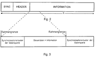
- the framework structure of the data streams is used in a suitable manner.
- the frame structure of the data streams is e.g. B. at the adaptation level of the data transmission, see Fig.1.
- the procedure can be as follows:
- the frame structure of the data is For example, limited by synchronization words of the data source, see Fig. 3. How the frame structure looks in detail is specified in the protocol H.245, H.263, G.723, as well as in data protocols.
- At least one synchronization pattern is set on a frame boundary.
- the control data contain, for example, information about the type of data source or contain error protection.
- the information block contains the data that are actually to be transmitted.
- the frame structure is fed into the INFORMATION field in the multiplex packet, FIG. 1, ie there are several frames within the INFORMATION field can be located.
- the receiver recognizes by means of HF that there is filling information in the data packet, this can be removed taking into account the filling rules according to a) and b). However, if more than 3 transmission errors occur per fill byte, it is no longer possible to reliably recognize the fill information.
- Another possibility is to replace the individual bit HF with t bits.
- t bits e.g. specify for which data source fill bits were used.
- HF consists of 2 bits. The following coding is possible with these: 00 no fill information in the data packet 01 Fill information for audio or video source 10th Fill information for data and control 11 Fill information for all sources
- the filling method with the zero and inserted bytes can also be used if no bit is set in the HEADER of the data block that bears information about filling bits. It is then conceivable that in one Additional header "of the data source contains the information about the filler bytes. This means that the process of filling with filler bits would be independent of the HEADER of the multiplexer. The individual data sources then have information about a possible filler with filler bits via their own additional header. It is also possible that the Additional headers can be defined by the multiplex protocol in the data slots of the data sources.
- an error-detecting code e.g. CRC
- an error-correcting code e.g. BCH, Reed-Solomon, RCPC
Landscapes
- Engineering & Computer Science (AREA)
- Signal Processing (AREA)
- Computer Networks & Wireless Communication (AREA)
- Multimedia (AREA)
- Physics & Mathematics (AREA)
- Probability & Statistics with Applications (AREA)
- Theoretical Computer Science (AREA)
- Detection And Prevention Of Errors In Transmission (AREA)
- Communication Control (AREA)
- Time-Division Multiplex Systems (AREA)
Applications Claiming Priority (4)
| Application Number | Priority Date | Filing Date | Title |
|---|---|---|---|
| DE19614738 | 1996-04-15 | ||
| DE19614738 | 1996-04-15 | ||
| DE19618386A DE19618386A1 (de) | 1996-04-15 | 1996-05-08 | Fehlerobustes Multiplexverfahren |
| DE19618386 | 1996-05-08 |
Publications (2)
| Publication Number | Publication Date |
|---|---|
| EP0802650A2 true EP0802650A2 (fr) | 1997-10-22 |
| EP0802650A3 EP0802650A3 (fr) | 2000-08-09 |
Family
ID=26024734
Family Applications (1)
| Application Number | Title | Priority Date | Filing Date |
|---|---|---|---|
| EP97104733A Withdrawn EP0802650A3 (fr) | 1996-04-15 | 1997-03-20 | Méthode de multiplexage faisant preuve de robustesse contre les erreurs |
Country Status (1)
| Country | Link |
|---|---|
| EP (1) | EP0802650A3 (fr) |
Family Cites Families (3)
| Publication number | Priority date | Publication date | Assignee | Title |
|---|---|---|---|---|
| US4905234A (en) * | 1987-06-03 | 1990-02-27 | General Electric Company | Apparatus and method for transmitting digital data over a radio communications channel |
| US4910754A (en) * | 1988-09-30 | 1990-03-20 | Data General Corporation | Initialization and synchronization method for a two-way communication link |
| US5426643A (en) * | 1993-11-01 | 1995-06-20 | Motorola Inc. | Apparatus and method for transmitting bit synchronous data over an unreliable channel |
-
1997
- 1997-03-20 EP EP97104733A patent/EP0802650A3/fr not_active Withdrawn
Also Published As
| Publication number | Publication date |
|---|---|
| EP0802650A3 (fr) | 2000-08-09 |
Similar Documents
| Publication | Publication Date | Title |
|---|---|---|
| DE60124164T2 (de) | Kodierung für in Paketen geordnete, serielle Daten | |
| DE60124443T2 (de) | 64b/66b-Dekodierung, für in Paketen geordnete, serielle Daten | |
| EP0827312A2 (fr) | Procédé de changement de configuration de paquets de données | |
| DE112019007412T5 (de) | Verfahren zum bereitstellen von pfadsignal-overhead im 64b/66b-zeichenstrom eines itu-t-metro-transportnetzwerks | |
| DE102006023878A1 (de) | Codieren und Decodieren von paketierten Daten | |
| DE2246826A1 (de) | System zur gesicherten blockweisen uebertragung von binaer codierten daten | |
| DE10393682T5 (de) | Verfahren zur Fehlerschutzcodierung und -decodierung von Nachrichten in einem Datenübertragungssystem mit Paketvermittlung | |
| CH693978A5 (de) | Verfahren zum Erweitern der Informationstragekapazitaet eines Datenrahmens bei einer Datenuebertragung. | |
| DE68927788T2 (de) | Datenvermittlungsbauweise zur Verschlüsselung von Paketen | |
| EP0802651A2 (fr) | Méthode de multiplexage faisant preuve de robustesse contre les erreurs avec retransmission éventuelle | |
| EP0802646A2 (fr) | Méthode de multiplexage faisant preuve de robustesse contre les erreurs avec champ de contrÔle d'en-tête | |
| DE69429654T2 (de) | Verfahren und system zur synchronisierung von kodierern und dekodierern in kommunikationsnetzwerken, wenn fehler detektiert werden | |
| DE10132577A1 (de) | Verfahren zur Übertragung von Datenpaketen | |
| EP0802650A2 (fr) | Méthode de multiplexage faisant preuve de robustesse contre les erreurs | |
| DE102010005702A1 (de) | Codieren und Decodieren von Daten zur Übertragung über einen fehlerhaften Übertragungskanal | |
| DE19618386A1 (de) | Fehlerobustes Multiplexverfahren | |
| DE3022047A1 (de) | Digitales uebertragungssystem mit codier- und decodiervorrichtungen | |
| DE69120252T2 (de) | Verfahren zur Nachrichtenübertragung über einen Fernsehkanal mit dem Teletextsystem | |
| EP1010285B1 (fr) | Procede et systeme de communication pour synchroniser deux dispositifs sur un processus de transmission de donnees predetermine | |
| EP1077562A1 (fr) | Procédé de synchronisation de pacquets à longueur variable dans un canal structuré en bit | |
| EP1512242A1 (fr) | Pointillage identique pour donnees d'identification d'equipement utilisateur et pour donnees utiles de canal hs-scch | |
| DE10201846A1 (de) | Automatisches Synchronisationsschema zur Härtung von ATM-Zellen | |
| EP3744021B1 (fr) | Station d'abonné pour un réseau de communication en série et procédé de correction des erreurs uniques dans un message d'un réseau de communication en série | |
| DE10219700C1 (de) | Verfahren zum Interleaving von Daten | |
| DE19705678A1 (de) | Verfahren zur Übertragung multimedialer Daten |
Legal Events
| Date | Code | Title | Description |
|---|---|---|---|
| PUAI | Public reference made under article 153(3) epc to a published international application that has entered the european phase |
Free format text: ORIGINAL CODE: 0009012 |
|
| AK | Designated contracting states |
Kind code of ref document: A2 Designated state(s): DE FR GB IT |
|
| PUAL | Search report despatched |
Free format text: ORIGINAL CODE: 0009013 |
|
| AK | Designated contracting states |
Kind code of ref document: A3 Designated state(s): DE FR GB IT |
|
| RIC1 | Information provided on ipc code assigned before grant |
Free format text: 7H 04L 1/00 A, 7H 04L 7/04 B, 7H 04L 1/08 B, 7H 04L 7/10 B |
|
| 17P | Request for examination filed |
Effective date: 20010201 |
|
| STAA | Information on the status of an ep patent application or granted ep patent |
Free format text: STATUS: THE APPLICATION IS DEEMED TO BE WITHDRAWN |
|
| 18D | Application deemed to be withdrawn |
Effective date: 20021001 |