EP0802608B1 - Spaltrohrmotor mit Versteifung des Statorspaltrohres - Google Patents
Spaltrohrmotor mit Versteifung des Statorspaltrohres Download PDFInfo
- Publication number
- EP0802608B1 EP0802608B1 EP97106204A EP97106204A EP0802608B1 EP 0802608 B1 EP0802608 B1 EP 0802608B1 EP 97106204 A EP97106204 A EP 97106204A EP 97106204 A EP97106204 A EP 97106204A EP 0802608 B1 EP0802608 B1 EP 0802608B1
- Authority
- EP
- European Patent Office
- Prior art keywords
- stator
- stator core
- rotor
- stiffeners
- inner circumferential
- Prior art date
- Legal status (The legal status is an assumption and is not a legal conclusion. Google has not performed a legal analysis and makes no representation as to the accuracy of the status listed.)
- Expired - Lifetime
Links
- 230000002787 reinforcement Effects 0.000 title 1
- 239000003351 stiffener Substances 0.000 claims description 38
- 238000004804 winding Methods 0.000 claims description 38
- 230000003014 reinforcing effect Effects 0.000 claims description 30
- 239000000919 ceramic Substances 0.000 claims description 10
- 239000012530 fluid Substances 0.000 description 9
- 229910000831 Steel Inorganic materials 0.000 description 4
- 238000003475 lamination Methods 0.000 description 4
- 239000010959 steel Substances 0.000 description 4
- 238000003780 insertion Methods 0.000 description 3
- 230000037431 insertion Effects 0.000 description 3
- 230000000717 retained effect Effects 0.000 description 2
- 229910000990 Ni alloy Inorganic materials 0.000 description 1
- 238000004891 communication Methods 0.000 description 1
- 238000001816 cooling Methods 0.000 description 1
- 230000001419 dependent effect Effects 0.000 description 1
- 238000009413 insulation Methods 0.000 description 1
- 238000003754 machining Methods 0.000 description 1
- 239000007769 metal material Substances 0.000 description 1
- 238000012986 modification Methods 0.000 description 1
- 230000004048 modification Effects 0.000 description 1
- 238000005086 pumping Methods 0.000 description 1
- 239000011347 resin Substances 0.000 description 1
- 229920005989 resin Polymers 0.000 description 1
- 239000002904 solvent Substances 0.000 description 1
- 238000003466 welding Methods 0.000 description 1
Images

Classifications
-
- H—ELECTRICITY
- H02—GENERATION; CONVERSION OR DISTRIBUTION OF ELECTRIC POWER
- H02K—DYNAMO-ELECTRIC MACHINES
- H02K1/00—Details of the magnetic circuit
- H02K1/06—Details of the magnetic circuit characterised by the shape, form or construction
- H02K1/12—Stationary parts of the magnetic circuit
- H02K1/16—Stator cores with slots for windings
- H02K1/165—Shape, form or location of the slots
-
- H—ELECTRICITY
- H02—GENERATION; CONVERSION OR DISTRIBUTION OF ELECTRIC POWER
- H02K—DYNAMO-ELECTRIC MACHINES
- H02K3/00—Details of windings
- H02K3/46—Fastening of windings on the stator or rotor structure
- H02K3/48—Fastening of windings on the stator or rotor structure in slots
- H02K3/487—Slot-closing devices
-
- H—ELECTRICITY
- H02—GENERATION; CONVERSION OR DISTRIBUTION OF ELECTRIC POWER
- H02K—DYNAMO-ELECTRIC MACHINES
- H02K5/00—Casings; Enclosures; Supports
- H02K5/04—Casings or enclosures characterised by the shape, form or construction thereof
- H02K5/12—Casings or enclosures characterised by the shape, form or construction thereof specially adapted for operating in liquid or gas
- H02K5/128—Casings or enclosures characterised by the shape, form or construction thereof specially adapted for operating in liquid or gas using air-gap sleeves or air-gap discs
Definitions
- the present invention relates to a canned motor for use with a pump actuatable thereby which is placed in a housing shared by the canned motor, the canned motor being suitable for use in high-temperature, high-pressure environments at temperatures of 400°C or higher and under pressures of 200 kgf/cm 2 or greater.
- FIGS. 1 and 2 of the accompanying drawings One conventional canned motor with a pressure-resistant structure is shown in FIGS. 1 and 2 of the accompanying drawings.
- the canned motor primarily comprises a rotor 2 fitted over a main shaft 1 and a stator 4 disposed around the rotor 2.
- a pump which can be actuated by the canned motor has an impeller (not shown) mounted on an end of an extension of the main shaft 1, which is rotatably supported by magnetic bearings.
- the stator 4 is fixedly supported in a cylindrical casing 3 having axially opposite end plates 13.
- the stator 4 comprises a stator core 7 of steel lamination and coil ends 8 which are housed in a space defined in the casing 3 and a stator can 15.
- the stator core 7 is mounted in the casing 3 hermetically covered by the stator can 15 in the form of a thin cylindrical wall covering an inner circumferential surface of the stator core 7.
- the rotor 2 comprises a rotor core 5 of steel lamination and slot bar and a rotor can 6 in the form of a thin cylindrical wall covering an outer circumferential surface of the rotor core 5 and spaced slightly radially inwardly from the stator can 15.
- the coil ends 8 project axially from axially opposite ends of the stator core 7, and are connected to windings 9 (see FIG. 2) disposed in the stator core 7.
- the stator core 7 has a plurality of slots 10 defined therein and successively positioned at given spaced intervals in the circumferential direction of the stator core 7.
- the slots 10 extend axially through the stator core 7 and have radially inner constricted ends 10b which are open at an inner circumferential surface of the stator core 7 and tapered portions 10c positioned slightly radially outwardly of the constricted open ends 10b.
- the windings 9, each comprising a plurality of twisted thin wires, are enclosed by sheets 11 of insulating paper and placed in respective winding chambers 10a in the respective slots 10.
- the windings 9 are retained in the winding chambers 10a against dislodgment therefrom by flat elongate wedge plates 12 of ceramics, for example, which are inserted into the respective tapered portions 10c.
- the stator can 15 is held against inner circumferential surfaces of the coil end reinforcing tubes 14 and the inner circumferential surface of the stator core 7.
- the stator can 15 prevents a fluid which is being handled by the pump from entering into the stator 4.
- the stator can 15 is made of a cylindrical thin sheet of a metallic material such as a nickel alloy or the like, and has a small thickness ranging from about 0.2 to 1 mm.
- the stator can 15 is fixedly joined to the end faces of the stator core 7 and/or the end plates 13 of the casing 3 as by welding.
- stator can 15 When the fluid being handled by the pump is subjected to a very high pressure such as of 200 kgf/cm 2 or higher, for example, the fluid introduced into the gap between the rotor 2 and the stator 4 exerts forces tending to press the stator can 15 into the slots 10. Therefore, portions of the stator can 15 forcibly project into the slots 10 through the constricted open ends 10b. The stator can 15 is thus liable to be damaged by edges of the constricted open ends 10b, and to push the wedge plates 12 for thereby displacing the windings 9, which may possibly suffer an insulation failure.
- the coil end reinforcing tubes 14 have to be relatively thin because the coil ends 8 are inserted therethrough. When the coil end reinforcing tubes 14 are subject to a high pressure, they are easily deformed particularly at their ends, developing steps at their junctions to the stator core 7. Those developed steps expose corners of the stator core 7 which tend to cause damage to the stator can 15. The coil end reinforcing tubes 14 may be prevented from being deformed if they have an increased wall thickness for their sufficient mechanical strength. However, the wall thickness of the coil end reinforcing tubes 14 cannot be substantially increased due to limitations posed by the shape of the slots 10 in the stator core 7 and the insertion of the coil ends 8.
- a canned motor comprising a rotor having a rotor core and a rotor can covering an outer circumferential surface of said rotor core.
- the canned motor further comprises a stator disposed around said rotor with a gap left therebetween for rotating the rotor.
- the stator has a stator core and a stator an covering an inner circumferential surface of the stator core.
- the stator is provided with a plurality of slots defined therein at circumferentially spaced regular intervals. The slots have respective open ends opening at the inner circumferential surface of the stator core , and a plurality of windings is disposed at the slots, respectively.
- the slots include respective winding chambers, with the windings housed therein. So as to provide for a uniform abutment of the stator can at the stator bore the slots at the stator bore are filled with a solvent free insulating resin. The open ends of the slots are filled such that also the edge regions of the stator are being covered. In this way it is assured that after machining the stator bore during the finishing step the inserted stator can is in uniform and tight abutment.
- stator When the gap between the rotor and the stator is held in a high-pressure environment, i.e., filled with a fluid under a high pressure, tending to push the stator can into the slots, the stator can is brought into contact with the stiffeners and pushes the stiffeners radially inwardly toward the winding chambers. However, the stiffeners are prevented from being displaced radially inwardly into the winding chambers by the constricted throats. The stator can is thus prevented from being damaged at the open ends, and the pressure acting on the stator can does not act in the winding chambers. Since the pressure acting on the stator can is prevented from acting on the wedge plates by the stiffeners, the windings in the winding chambers are prevented from being unduly damaged.
- Each of the stiffeners comprises a round rod of nonmagnetic ceramics having a circular cross-sectional shape. Forces which act on the stiffeners each in the form of a round rod of nonmagnetic ceramics when the stator can is deformed under a pressure buildup in the gap between the rotor and the stator are smoothly distributed over the stator core. Therefore, the stator can is prevented from being unduly deformed and damaged, and no undue forces are applied to the windings in the winding chambers.
- Cylindrical coil end reinforcing tubes are joined to respective opposite axial ends of the stator core and each having a wall thickness substantially equal to a radial dimension of the stiffeners, the coil end reinforcing tubes having respective inner circumferential surfaces contiguous to the inner circumferential surface of the stator core, the stator can covering the inner circumferential surfaces of the coil end reinforcing tubes and the stator core. Since the coil end reinforcing tubes are sufficiently thick and strong, they are effective in preventing the stator can from being damaged in the high-pressure environment at the junctions between the stator core and the coil end reinforcing tubes.
- a canned motor according to the present invention comprises a rotor 2 fitted over a main shaft 1 and a stator 4 disposed around the rotor 2 with a radial gap left therebetween.
- a pump which can be actuated by the canned motor has an impeller (not shown) mounted on an end of an extension of the main shaft 1, which is rotatably supported by magnetic bearings.
- the canned motor and the pump are placed in a housing.
- the stator 4 is fixedly supported in a cylindrical casing 3 having axially opposite end plates 13.
- the stator 4 comprises a stator core 7 of steel lamination and coil ends 8 which are housed in a space defined in the casing 3 and a stator can 15 extending radially inwardly of the casing 3 and radially outwardly of the rotor 2.
- the stator core 7 is mounted inside of the cylindrical casing 13.
- the rotor 2 comprises a rotor core 5 of steel lamination and slot bar and a rotor can 6 in the form of a thin cylindrical wall covering an outer circumferential surface of the rotor core 5 and spaced slightly radially inwardly from the stator can 15.
- the coil ends 8 project axially from axially opposite ends of the stator core 7, and are connected to windings 9 (see FIG. 2) disposed in the stator core 7.
- the stator core 7 has a plurality of slots 20 defined therein and successively positioned at given spaced intervals in the circumferential direction of the stator core 7.
- the slots 20 extend axially through the stator core 7 and have respective winding chambers 20a which accommodate the windings 9, respectively, respective open ends 20b extending radially inwardly from the winding chambers 20a and opening at an inner circumferential surface of the stator core 7, respective constricted throats 20d near the winding chambers 20a in communication therewith, and respective stiffener chambers 20e defined between the constricted throats 20d and the open ends 20b and housing respective stiffeners 21.
- the slots 20 have a radial depth which is greater than the radial depth of the slots 10 shown in FIG. 2.
- the windings 9, each comprising a plurality of twisted thin wires, are enclosed by sheets 11 of insulating paper and placed in respective winding chambers 20a in the respective slots 20.
- the windings 9 are retained in the winding chambers 20a against dislodgment therefrom by flat elongate wedge plates 12 of nonmagnetic ceramics, for example, which are inserted into respective tapered portions of the winding chambers 20a near the constricted throats 20d.
- Each of the stiffener chambers 20e is defined by a pair of semicylindrical recesses defined in confronting wall surfaces of the slot 20 in the stator core 7.
- a stiffener 21 in the form of a rod of ceramics having a circular cross section is mounted in each of the stiffener chambers 20e.
- the stiffeners 21 thus placed in the respective stiffener chambers 20e close the open ends 20b, and have round outer circumferential surfaces positioned closely to the outer circumferential surface of the stator can 15.
- the stiffeners 21 and the stator can 15 extend axially parallel to each other in closely spaced relation to or in contact with each other.
- stator can 15 when the gap between the rotor 2 and the stator 4 is held in a high-pressure environment, i.e., filled with a fluid under a high pressure, tending to push the stator can 15 into the slots 20, the stator can 15 is brought into contact with the stiffeners 21 and pushes the stiffeners 21 radially inwardly toward the winding chambers 20a. However, the stiffeners 21 are prevented from being displaced radially inwardly into the winding chambers 20a by the constricted throats 20d. The stator can 15 is thus prevented from being damaged at the open ends 20b, and the pressure acting on the stator can 15 does not act in the winding chambers 20e. Since the pressure acting on the stator can 15 is prevented from acting on the wedge plates 12 by the stiffeners 21, the windings 9 in the winding chambers 20e are prevented from being unduly damaged.
- stiffeners 21 are in the form of round rods of ceramics, they are sufficiently resistant to compressive stresses.
- the stiffeners 21 are sufficiently strong even if a fluid being handled by the pump has a temperature in excess of 40°C, for example, forces which act on the stiffeners 21 when the stator can 15 is deformed under a pressure buildup in the gap between the rotor 2 and the stator 4 are smoothly distributed over the stator core 7.
- the stiffeners 21 in the form of round rods of ceramics can easily be manufactured.
- the stiffeners 21 are not limited to round rods of ceramics, but may be of a triangular cross-sectional shape with a vertex thereof directed radially inwardly, or any of various other cross-sectional shapes including a rectangular cross-sectional shape, an elliptical cross-sectional shape, etc.
- the stiffeners 21 may be of an elongate structure extending substantially the full length of the stator core 7 and may be mounted respectively in the slots 20. However, each of the stiffeners 21 may comprise a plurality of short members arranged in series. Such stiffeners can easily be manufactured and assembled efficiently.
- the stator can 15 is held against inner circumferential surfaces of the coil end reinforcing tubes 22 and the inner circumferential surface of the stator core 7.
- Each of the coil end reinforcing tubes 22 has a wall thickness matching the height of the stiffeners 21, i.e., the diameter of the round rods of ceramics used as the stiffeners 21.
- the slots 20 have a relatively large radial depth, with the windings 9 and the coil ends 8 being positioned more radially outwardly than the windings 9 and the coil ends 8 of the conventional canned motor shown in FIG. 2. Therefore, the relatively thick coil end reinforcing tubes 22 can be joined to the opposite axial ends of the stator core 7.
- the coil end reinforcing tubes 22 are relatively thick and hence strong, they are effective in preventing the stator can 15 from being deformed in regions axially outwardly from the opposite axial ends of the stator core 7.
- the stator can 15 which is of a cylindrical shape having a small wall thickness, is fixed to and covers continuous inner circumferential surfaces of the coil end reinforcing tubes 22 and the stator core 7.
- the stator can 15 prevents the fluid which is being handled by the pump from entering into the stator 4.
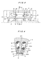
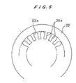
- Substantially disk-shaped reinforcing plates 23 are disposed at the junctions between the stator core 7 and the coil end reinforcing tubes 22.
- the reinforcing plates 23 have radially outer ends held against the inner circumferential surface of the casing 1 and radially inner ends held against the outer circumferential surfaces of the coil end reinforcing tubes 22.
- Each of the reinforcing plates 23 has a plurality of coil end insertion grooves 23a (see FIGS. 3 and 5) defined therein which extend radially outwardly from and are open at its inner circumferential edge.
- the coil ends 8 extend through the coil end insertion grooves 23a as shown in FIG. 3.
- the reinforcing plates 23 positioned at the respective axial ends of the coil end reinforcing tubes 22 prevent the coil end reinforcing tubes 22 from being unduly deformed, thus preventing the stator core 7 and the coil end reinforcing tubes 22 from being displaced relatively to each other and developing steps therebetween.
Landscapes
- Engineering & Computer Science (AREA)
- Power Engineering (AREA)
- Structures Of Non-Positive Displacement Pumps (AREA)
- Motor Or Generator Frames (AREA)
Claims (3)
- Ein gekapselter Motor geeignet zur Verwendung in einer Hochdruckumgebung, wobei Folgendes vorgesehen ist:ein Rotor (2) mit einem Rotorkern (5) und einer Rotorkapsel (6), die eine Außenumfangsoberfläche des Rotorkerns (5) abdeckt; undein Stator (4) angeordnet um den Rotor (5) herum, wobei ein Spalt dazwischen zur Drehung des Rotors (2) verbleibt, und wobei der Stator (4) einenStatorkern (7) besitzt und eine Statorkapsel (15) eine Innenumfangsoberfläche des Statorkems (7) abdeckt;wobei der Statorkern (7) eine Vielzahl von Schlitzen (20) darinnen definiert aufweist, und zwar an umfangsmäßig beabstandeten regelmäßigen Intervallen und mit entsprechenden offenen Enden (20b), die sich an der erwähnten Innenoberfläche des Statorkerns (7) öffnen, und ferner mit einer Vielzahl von Wicklungen (9), angeordnet in den entsprechenden Schlitzen (20), wobei die Schlitze entsprechende Wicklungskammern (20) aufweisen, in denen die Wicklungen (9) untergebracht sind, wobei die Schlitze ferner entsprechende eingeschränkte Kehlen (20d) radial nach innen gegenüber den Wicklungskammern (20a) angeordnet aufweisen, und schließlich entsprechende Versteifungskammern (20e) radial nach innen beabstandet gegenüber den eingeschränkten Kehlen (20d), wobei die erwähnten offenen Enden radial nach innen gegenüber den Versteifungskammern angeordnet sind, wobei die offenen Enden durch die Statorkapsel abgedeckt sind; undwobei der Statorkern (7) ferner eine Vielzahl von Versteifern (21) aufweist, untergebracht jeweils in den Versteiferkammern (20e), dadurch gekennzeichnet, dass die Statorkapsel (15) und die erwähnten Versteifer (21) miteinander in Kontakt stehen oder in einer eng beabstandeten Beziehung miteinander derart stehen, dass die erwähnte Statorkapsel in Kontakt mit den erwähnten Versteifern dann gebracht wird, wenn der erwähnte Spalt unter der Hochdrukkumgebung gehalten ist.
- Gekapselter Motor nach Anspruch 1, wobei jeder Versteifer (21) eine runde Stange aus Keramikmaterial mit kreisförmiger Querschnittsgestalt ist.
- Gekapselter Motor nach Anspruch 1 oder 2, wobei ferner zylindrische Spulenendverstärkungsrohre (22) vorgesehen sind, und zwar verbunden mit entsprechenden entgegengesetzt liegenden Axialenden des Statorkerns (7), und wobei jede eine Wanddicke gleich einer Radialdimension der erwähnten Versteifer (21) besitzt, und wobei die Spulenendverstärkungsrohre (22) entsprechende innere Umfangsoberflächen besitzen und zwar angrenzend an die innere Umfangsoberfläche des Statorkerns (7), wobei die Statorkapsel (15) die Innenumfangsoberflächen der Spulenendverstärkungsrohre (22) und den Statorkern (7) abdeckt.
Applications Claiming Priority (3)
| Application Number | Priority Date | Filing Date | Title |
|---|---|---|---|
| JP11841796 | 1996-04-16 | ||
| JP8118417A JPH09280190A (ja) | 1996-04-16 | 1996-04-16 | キャンドモータ |
| JP118417/96 | 1996-04-16 |
Publications (2)
| Publication Number | Publication Date |
|---|---|
| EP0802608A1 EP0802608A1 (de) | 1997-10-22 |
| EP0802608B1 true EP0802608B1 (de) | 2001-10-31 |
Family
ID=14736138
Family Applications (1)
| Application Number | Title | Priority Date | Filing Date |
|---|---|---|---|
| EP97106204A Expired - Lifetime EP0802608B1 (de) | 1996-04-16 | 1997-04-15 | Spaltrohrmotor mit Versteifung des Statorspaltrohres |
Country Status (4)
| Country | Link |
|---|---|
| US (1) | US6057624A (de) |
| EP (1) | EP0802608B1 (de) |
| JP (1) | JPH09280190A (de) |
| DE (1) | DE69707743T2 (de) |
Families Citing this family (18)
| Publication number | Priority date | Publication date | Assignee | Title |
|---|---|---|---|---|
| GB9823926D0 (en) * | 1998-11-03 | 1998-12-30 | Lucas Ind Plc | Rotor for an electric machine,retainer for retaining a winding in a winding in a recess in a rotor,and method of manufacturing a rotor |
| JP3593059B2 (ja) * | 2001-05-28 | 2004-11-24 | 三菱電機株式会社 | 車両用交流発電機 |
| FI112989B (fi) * | 2002-05-08 | 2004-02-13 | Kone Corp | Hissikoneiston sähkömoottorin staattorikäämityksen kiinnitys |
| FI112990B (fi) * | 2002-05-08 | 2004-02-13 | Kone Corp | Hissikoneiston sähkömoottorin staattorikäämitys |
| DE10232389B4 (de) * | 2002-07-17 | 2005-11-03 | Liebherr-Aerospace Lindenberg Gmbh | Naßlaufender Elektromotor und Verfahren zu seiner Herstellung |
| US6930427B2 (en) * | 2002-09-30 | 2005-08-16 | Reliance Electric Technologies, Llc | Electric apparatus having a stator with insulated end laminations within the central opening of end plates |
| US20040061409A1 (en) * | 2002-09-30 | 2004-04-01 | Grant Barron D. | Method for making electrical stator and stator made by same |
| JP3970260B2 (ja) | 2004-04-23 | 2007-09-05 | 三菱重工業株式会社 | ポンプ |
| US7498710B2 (en) * | 2006-03-29 | 2009-03-03 | Rao Dantam K | Cooling of stator windings |
| FR2903245B1 (fr) * | 2006-06-28 | 2015-03-27 | Valeo Equip Electr Moteur | Stator pour machine electrique tournante et machine electrique tournante comportant un tel stator |
| US7808148B2 (en) * | 2007-09-11 | 2010-10-05 | Remy International | Stator winding assembly and method |
| DE102010055821B4 (de) * | 2010-12-23 | 2014-09-25 | Avl Trimerics Gmbh | Elektrische Maschine mit Spaltrohr und Verfahren zur Herstellung derselben |
| KR101251261B1 (ko) | 2011-11-16 | 2013-04-10 | 현대자동차주식회사 | 코깅토크 저감형 캔드모터 |
| DE102013004336A1 (de) * | 2013-03-14 | 2014-09-18 | Wilo Se | Pumpenaggregat |
| KR101509901B1 (ko) | 2013-07-18 | 2015-04-08 | 현대자동차주식회사 | 캔드 모터 펌프 |
| KR101543075B1 (ko) | 2013-07-18 | 2015-08-10 | 현대자동차주식회사 | 캔드 모터 펌프 |
| KR101519205B1 (ko) | 2013-07-18 | 2015-05-12 | 현대자동차주식회사 | 캔드 모터 펌프 |
| JP6109052B2 (ja) * | 2013-12-10 | 2017-04-05 | 株式会社帝国電機製作所 | キャンドモータ |
Family Cites Families (12)
| Publication number | Priority date | Publication date | Assignee | Title |
|---|---|---|---|---|
| BE383220A (de) * | 1930-10-08 | |||
| US2640956A (en) * | 1950-05-16 | 1953-06-02 | Westinghouse Electric Corp | Single phase capacitor motor |
| US2858462A (en) * | 1957-05-09 | 1958-10-28 | Gen Electric | Slot wedge arrangement for use in dynamoelectric machine core members |
| GB1119611A (en) * | 1966-04-20 | 1968-07-10 | Ferranti Ltd | Improvements relating to dynamo-electric machines |
| DE2342050B2 (de) * | 1973-08-20 | 1979-11-15 | Hermetic-Pumpen Gmbh, 7803 Gundelfingen | Ständerblechpaket für elektrische Spaltrohrmotoren |
| US4147946A (en) * | 1977-05-31 | 1979-04-03 | Sundstrand Corporation | Rotor structure for an electric machine |
| US4572980A (en) * | 1984-03-08 | 1986-02-25 | General Electric Company | Stator core for large electric generator with dual dovetail slots for engaging wedges |
| US4607183A (en) * | 1984-11-14 | 1986-08-19 | General Electric Company | Dynamoelectric machine slot wedges with abrasion resistant layer |
| JPH0620357B2 (ja) * | 1988-10-12 | 1994-03-16 | 株式会社帝国電機製作所 | キャンドモータおよびその製造方法 |
| CZ280517B6 (cs) * | 1990-07-03 | 1996-02-14 | Čkd Trakce, A.S. | Isolační systém vinutí elektrického stroje |
| FR2701610B1 (fr) * | 1993-02-15 | 1995-04-21 | Andre Douanne | Dispositif de pivotement pour rotor noyé. |
| US5644181A (en) * | 1995-01-05 | 1997-07-01 | Dayton-Phoenix Group, Inc. | Stator lamination design having a tapered opening |
-
1996
- 1996-04-16 JP JP8118417A patent/JPH09280190A/ja active Pending
-
1997
- 1997-04-10 US US08/834,853 patent/US6057624A/en not_active Expired - Fee Related
- 1997-04-15 EP EP97106204A patent/EP0802608B1/de not_active Expired - Lifetime
- 1997-04-15 DE DE69707743T patent/DE69707743T2/de not_active Expired - Fee Related
Also Published As
| Publication number | Publication date |
|---|---|
| EP0802608A1 (de) | 1997-10-22 |
| US6057624A (en) | 2000-05-02 |
| DE69707743T2 (de) | 2002-08-08 |
| JPH09280190A (ja) | 1997-10-28 |
| DE69707743D1 (de) | 2001-12-06 |
Similar Documents
| Publication | Publication Date | Title |
|---|---|---|
| EP0802608B1 (de) | Spaltrohrmotor mit Versteifung des Statorspaltrohres | |
| US5990588A (en) | Induction motor driven seal-less pump | |
| US6580193B2 (en) | Rotary electric machine and manufacturing method therefor | |
| US4387316A (en) | Dynamoelectric machine stator wedges and method | |
| US6700273B1 (en) | Gas transfer machine | |
| EP2031734B1 (de) | Elektrische Maschine mit einer Spulenisolierung | |
| US5986366A (en) | Rotor for a dynamoelectric machine | |
| GB2320979A (en) | Composite barrier can for a magnetic coupling | |
| US4797588A (en) | Stator cooling for dynamoelectric machine | |
| CN102138271A (zh) | 旋转电机的定子以及制造该定子的方法 | |
| US4146809A (en) | Sleeve for a rotor of a dynamoelectric machine | |
| US5189328A (en) | Laminated motor bearing for electrical submersible pump | |
| US6060805A (en) | Canned motor | |
| GB2145882A (en) | Partition structure for a dynamo-electric machine | |
| US5432391A (en) | Conformable dynamoelectric machine field distance blocks and methods of installation | |
| US4454439A (en) | Air gap winding rotating electric machine | |
| US2809310A (en) | Sealed electric motor | |
| US6483220B1 (en) | Precision-wound rotor for a dynamoelectric machine | |
| US3469309A (en) | Method of manufacturing squirrel-cage rotor | |
| US4439704A (en) | Permanent magnet excited rotor for a synchronous machine | |
| JPH054772U (ja) | 高速誘導型acモータのロータ組立構造 | |
| EP2528201A1 (de) | Verfahren zum Anbringen eines Rückhaltesystems über einen Rotorkern einer elektrischen Maschine und Rotoranordnung | |
| EP0045125A1 (de) | Statoren für elektrische Motoren | |
| US3031593A (en) | Dynamoelectric machine | |
| EP1341287A2 (de) | Rotor für eine elektrische drehende Maschine |
Legal Events
| Date | Code | Title | Description |
|---|---|---|---|
| PUAI | Public reference made under article 153(3) epc to a published international application that has entered the european phase |
Free format text: ORIGINAL CODE: 0009012 |
|
| AK | Designated contracting states |
Kind code of ref document: A1 Designated state(s): CH DE GB LI NL |
|
| 17P | Request for examination filed |
Effective date: 19980417 |
|
| 17Q | First examination report despatched |
Effective date: 19990519 |
|
| GRAG | Despatch of communication of intention to grant |
Free format text: ORIGINAL CODE: EPIDOS AGRA |
|
| GRAG | Despatch of communication of intention to grant |
Free format text: ORIGINAL CODE: EPIDOS AGRA |
|
| GRAH | Despatch of communication of intention to grant a patent |
Free format text: ORIGINAL CODE: EPIDOS IGRA |
|
| GRAH | Despatch of communication of intention to grant a patent |
Free format text: ORIGINAL CODE: EPIDOS IGRA |
|
| GRAA | (expected) grant |
Free format text: ORIGINAL CODE: 0009210 |
|
| AK | Designated contracting states |
Kind code of ref document: B1 Designated state(s): CH DE GB LI NL |
|
| REG | Reference to a national code |
Ref country code: CH Ref legal event code: EP |
|
| REF | Corresponds to: |
Ref document number: 69707743 Country of ref document: DE Date of ref document: 20011206 |
|
| REG | Reference to a national code |
Ref country code: GB Ref legal event code: IF02 |
|
| REG | Reference to a national code |
Ref country code: CH Ref legal event code: NV Representative=s name: E. BLUM & CO. PATENTANWAELTE |
|
| PLBE | No opposition filed within time limit |
Free format text: ORIGINAL CODE: 0009261 |
|
| STAA | Information on the status of an ep patent application or granted ep patent |
Free format text: STATUS: NO OPPOSITION FILED WITHIN TIME LIMIT |
|
| 26N | No opposition filed | ||
| PGFP | Annual fee paid to national office [announced via postgrant information from national office to epo] |
Ref country code: GB Payment date: 20030401 Year of fee payment: 7 |
|
| PGFP | Annual fee paid to national office [announced via postgrant information from national office to epo] |
Ref country code: CH Payment date: 20030417 Year of fee payment: 7 |
|
| PGFP | Annual fee paid to national office [announced via postgrant information from national office to epo] |
Ref country code: NL Payment date: 20030428 Year of fee payment: 7 |
|
| PGFP | Annual fee paid to national office [announced via postgrant information from national office to epo] |
Ref country code: DE Payment date: 20030430 Year of fee payment: 7 |
|
| PG25 | Lapsed in a contracting state [announced via postgrant information from national office to epo] |
Ref country code: GB Free format text: LAPSE BECAUSE OF NON-PAYMENT OF DUE FEES Effective date: 20040415 |
|
| PG25 | Lapsed in a contracting state [announced via postgrant information from national office to epo] |
Ref country code: LI Free format text: LAPSE BECAUSE OF NON-PAYMENT OF DUE FEES Effective date: 20040430 Ref country code: CH Free format text: LAPSE BECAUSE OF NON-PAYMENT OF DUE FEES Effective date: 20040430 |
|
| PG25 | Lapsed in a contracting state [announced via postgrant information from national office to epo] |
Ref country code: NL Free format text: LAPSE BECAUSE OF NON-PAYMENT OF DUE FEES Effective date: 20041101 |
|
| PG25 | Lapsed in a contracting state [announced via postgrant information from national office to epo] |
Ref country code: DE Free format text: LAPSE BECAUSE OF NON-PAYMENT OF DUE FEES Effective date: 20041103 |
|
| GBPC | Gb: european patent ceased through non-payment of renewal fee |
Effective date: 20040415 |
|
| REG | Reference to a national code |
Ref country code: CH Ref legal event code: PL |
|
| NLV4 | Nl: lapsed or anulled due to non-payment of the annual fee |
Effective date: 20041101 |