EP0802552B1 - Electrical switch with undervoltage release - Google Patents
Electrical switch with undervoltage release Download PDFInfo
- Publication number
- EP0802552B1 EP0802552B1 EP97106350A EP97106350A EP0802552B1 EP 0802552 B1 EP0802552 B1 EP 0802552B1 EP 97106350 A EP97106350 A EP 97106350A EP 97106350 A EP97106350 A EP 97106350A EP 0802552 B1 EP0802552 B1 EP 0802552B1
- Authority
- EP
- European Patent Office
- Prior art keywords
- switch
- magnet armature
- switch according
- switching element
- fixing slide
- Prior art date
- Legal status (The legal status is an assumption and is not a legal conclusion. Google has not performed a legal analysis and makes no representation as to the accuracy of the status listed.)
- Expired - Lifetime
Links
- 238000003780 insertion Methods 0.000 claims description 14
- 230000037431 insertion Effects 0.000 claims description 14
- 238000006073 displacement reaction Methods 0.000 description 27
- 230000008878 coupling Effects 0.000 description 13
- 238000010168 coupling process Methods 0.000 description 13
- 238000005859 coupling reaction Methods 0.000 description 13
- 238000004519 manufacturing process Methods 0.000 description 11
- 210000002105 tongue Anatomy 0.000 description 7
- 238000010276 construction Methods 0.000 description 5
- 238000012546 transfer Methods 0.000 description 5
- 230000005540 biological transmission Effects 0.000 description 4
- 238000013461 design Methods 0.000 description 4
- 230000000694 effects Effects 0.000 description 2
- 238000009434 installation Methods 0.000 description 2
- 238000000034 method Methods 0.000 description 2
- 238000007789 sealing Methods 0.000 description 2
- 239000002699 waste material Substances 0.000 description 2
- 239000003795 chemical substances by application Substances 0.000 description 1
- 230000006835 compression Effects 0.000 description 1
- 238000007906 compression Methods 0.000 description 1
- 238000002347 injection Methods 0.000 description 1
- 239000007924 injection Substances 0.000 description 1
- 230000002452 interceptive effect Effects 0.000 description 1
- 239000000463 material Substances 0.000 description 1
- 239000002184 metal Substances 0.000 description 1
- 238000012544 monitoring process Methods 0.000 description 1
- 238000012545 processing Methods 0.000 description 1
- 239000000565 sealant Substances 0.000 description 1
- 238000013519 translation Methods 0.000 description 1
- 230000001960 triggered effect Effects 0.000 description 1
- 238000004804 winding Methods 0.000 description 1
Images


Classifications
-
- H—ELECTRICITY
- H01—ELECTRIC ELEMENTS
- H01H—ELECTRIC SWITCHES; RELAYS; SELECTORS; EMERGENCY PROTECTIVE DEVICES
- H01H83/00—Protective switches, e.g. circuit-breaking switches, or protective relays operated by abnormal electrical conditions otherwise than solely by excess current
- H01H83/12—Protective switches, e.g. circuit-breaking switches, or protective relays operated by abnormal electrical conditions otherwise than solely by excess current operated by voltage falling below a predetermined value, e.g. for no-volt protection
Definitions
- the invention relates to an electrical switch with the features of the preamble of claim 1.
- Such switches are known from DE-A-4 341 214 and from DE-A-3 340 250. These switches work with a magnetic circuit for electromagnetic Undervoltage release together. If the monitored voltage drops below one determined value, the magnetic circuit is opened and consequently one manually operated switching element transferred to its off position. In this switch-off position the circuit of the electrical switch is interrupted.
- the Switching element is coupled to the movable magnet armature of the magnetic circuit in such a way that when the switching element is in the switched-off position, the magnetic circuit is automatically closed again. As a result, the magnetic circuit is also without The presence of the required minimum voltage is closed again.
- the electromagnet therefore only needs to be closed with a magnetic circuit for the magnet armature generate the required holding force. This holding force is much smaller than the attraction force to close the magnetic circuit when it is back Tension.
- a disadvantage of the known switches is the complex coupling between the switching element and the magnet armature.
- the switching movement of the Switching device from its on position to its off position is over transfer complex rocker arm designs to the magnetic armature.
- This Coupling complicates the manufacture of the undervoltage release necessary components and increases manufacturing costs also allow the complicated rocker arm designs are only relatively small Power transmission between the switching element and the magnet armature.
- Already minor Signs of wear and tear of these swivel levers can make the proper Interfering with the operation of the undervoltage release.
- individual coupling components could be dimensioned stronger become.
- this has an increased space requirement for the switch housing and / or a housing provided for the magnetic circuit.
- the invention has for its object an electrical switch of the beginning to improve the type mentioned in terms of construction and safety.
- the switching element only has to be proportionate Apply small forces to keep the magnet armature in its tightened position To move the position on the magnetic core and fix it there.
- the good power transmission caused by the fixing slide from the switching element to the Magnetic anchors also favor a simple construction of the Switching element and its stability during the operating life of the switch.
- the fixing slide is preferably mounted displaceably on the housing side, as a result of which Wrong movements and faulty power transmissions between the switching element and Magnetic armatures can be reliably avoided.
- the voltage connected to the electromagnet and to be monitored is in a preferred embodiment, the mains voltage for the circuit of the electrical switch.
- the electromagnet can also be connected to another Voltage must be connected.
- the electromagnet is connected to two phases of a multi-phase power system.
- the undervoltage unit is preferably used with a bipolar switch combined
- the electrical switch is in a preferred Embodiment designed as an overcurrent protection switch and each has this Phase a corresponding overcurrent trip element, especially one on one Switch lock of the circuit breaker acting bimetal strips.
- the undervoltage unit with the magnetic circuit can be in the switch housing be installed or integrated in a separate housing, which by suitable fasteners is coupled to the switch housing.
- the coil connections of the electromagnet are preferably via a Rectifier with the contact connections connected to the voltage to be monitored the undervoltage unit electrically connected.
- the switching element is a two-armed rocker switch formed, which is pivotally mounted on the switch housing. While the pivoting of the rocker switch into its off position becomes its pivoting movement converted directly into a translational movement of the fixing slide.
- the switching element is in the form of one or two push buttons trained, which pressurizes the user to operate them manually and thereby be slowly shifted.
- the Longitudinal movement of the push button parallel to the translational movement of the fixing slide, so that the push button and the fixing slide are particularly easily coupled can be
- the magnetic circuit is opened and the automatic sequence is repeated Turning off the switch and closing the magnetic circuit started. This automatic sequence when attempting to transfer the switching element to its switch-on position helps to ensure that the safety requirements for the Switches are met.
- the fixing slide and the switching element are preferably in such a manner with one another connected that the fixing slide from the switching element in its on position is decoupled.
- the fixing slide and the magnet armature are opposite the switching element is freely movable. This free mobility ensures reliable release of the switch in the event of undervoltage. Moreover supports the decoupling of the switching element and the fixing slide the aforementioned Sequence of events when trying to switch the switching element in spite of undervoltage Switch to the on position.
- the fixing slide has one transverse to it Movement direction extending shoulder on.
- undervoltage i.e. if the magnet armature falls off, the fixer slide is moved and acted upon a switch lock connected to the switching element.
- the key switch is to open and close a switching contact of the circuit between a Contact opening position and a contact closing position movable and transfers the switching element to its switch-off position when the switching contact is opened.
- the fixing slide ensures that undervoltage is triggered a technically simple automatic sequence for interrupting the circuit and closing the magnetic circuit again. For triggering this automatic sequence, i.e. the application of the key switch, apart from the fixing slide itself, no other components are necessary. This supports a space-saving and technically simple construction of the electrical Switch and the undervoltage unit.
- a spring element In a preferred embodiment is between the fixing slide and the Magnetic armature arranged a spring element. Its spring force can be production-related Dimensional tolerances and deviations of the switching element, the fixing slide and compensate for the magnetic tank, thereby ensuring the safe operation of the switch. Due to the balancing effect of the spring element is also the part of the committee in the production of the aforementioned Components lower, which also reduces the manufacturing costs of the electrical Switch and the undervoltage unit can be further reduced.
- the compensating spring element is preferably in the form of an arched spring washer formed with a concave side facing the magnet armature.
- the spring element is supported on the magnetic armature, in particular on its the face facing the fixing slide, and is therefore without additional Aids between the fixing slide and the magnetic armature are fixed above
- the spring washer between the fixing slide and magnetic armature can be integrated in a space-saving manner and ensures particularly effective transmission the spring force on the fixing slide in its direction of displacement.
- the magnet armature with the fixing slide captively connected. This creates a mechanically particularly stable drive coupling between the two components. Faulty functional processes to open and close the magnetic circuit are therefore a priori avoided.
- the captive coupling is e.g. through a positive or realized a material connection.
- the coupling can be rigid or movable his.
- the magnet armature is approximately transverse to it the end face facing the fixing slide is penetrated by an anchor slot.
- This anchor slot takes a fixing pin arranged on the fixing slide on.
- the fixing pin is preferably an integral part of the fixing slide and thereby supports a mechanically stable coupling between the Fixing slide and the magnetic anchor.
- the fixing pin according to Art a positive connection with the magnet armature connected and simplified thereby the assembly of the components.
- the fixing pin penetrates the fixing slide forth the magnet armature in the direction of the contact surface facing the magnetic core of the magnet armature.
- the fixing pin engages there in an advantageous manner Design the slot edge of the anchor slot.
- a crossbar is formed, which is in the assembled state of the fixing pin the slot edge of the anchor slot on the contact surface
- the fixer pin and its associated crossbar are particularly good T-shaped.
- the anchor slot is cross-shaped with two intersecting, longitudinal slits of different lengths.
- the two longitudinal slots are dimensioned in such a way that the T-shaped fixing pin is first inserted into the longer longitudinal slot used and with the crossbar through this longitudinal slot is passed through and then rotated by 90 ° into the shorter longitudinal slot snaps into place. In this way, the fixer slide is additionally secured against rotation mounted on the magnet armature and thus even better against unwanted changes in position protected
- the fixing pin is in an additional Function as a centering and fixing element effective for this spring element. Without further aids, this spring element is held captive on the fixing pin
- the spring element is designed, for example, as a coil spring and surrounds the Locating pin with a small radial distance. This is designed as a spring washer Spring element transversely to the plane of the disc from a slot for receiving the fixing pin enforced and thereby also stored captive.
- the direction of displacement is of the fixing slide in a preferred embodiment in parallel for the direction of the magnet armature.
- the direction of displacement is preferably of the fixing slide at the same time in the plane of movement of the switching element on
- the plate level about the direction of displacement and a transverse direction extending across it is.
- This simple shape allows the fixing slide to be manufactured as cheap mass-produced items.
- This fixing slide is advantageous as a stamped part Can also be made from a suitable plastic or metal the plate shape of the fixing slide further miniaturizes the switch and / or the undervoltage unit.
- the one carrying the coil of the electromagnet Coil body at least two over the pole face of the magnetic core in the direction of drop protruding from the magnet armature and running approximately in the direction of the waste Leaders on.
- These guide bars are opposite one another arranged and flank the magnet armature laterally as a movement guide.
- the magnet armature in the direction of the fall and in the direction performs controlled movements in its tightened position. This contributes to this in that the components of the electrical drive coupled together Switch and the undervoltage unit no undesirable changes in position exhibit.
- these guideways are indirect as a movement guide effective for the locking slide coupled to the magnetic armature.
- the guide webs are an integral part of the bobbin, which is injection molded or cast from a suitable plastic is.
- Stop lugs are transverse to the direction of waste of the magnet armature and are directed towards each other. These are preferably Stop lugs are an integral part of the guide bars and are therefore manufactured easy to manufacture.
- the electromagnet of the magnetic circuit a horseshoe-like or U-shaped magnetic core.
- the freeers of the two U-legs of the magnetic core each have a pole face, which when closed Magnetic circuit contacted with the contact surface of the magnet armature are.
- the coil body carrying the coil of the electromagnet is in the In order to make the electromagnet easy to assemble in several parts to be able to accommodate the magnetic core.
- the bobbin it is advantageous to use the bobbin to be formed in two parts with the division plane as the symmetry plane in this The case for the assembly of the bobbin is the manufacture of a single one Component necessary. This takes into account a production-oriented and inexpensive Manufacture of the electromagnet.
- the magnetic core is fixed to the coil body.
- the U level of the horseshoe lies
- the magnetic core is approximately in the division plane of the bobbin.
- the magnetic core without additional Fixing agent between the two partial bodies acting as clamping jaws of the bobbin fixed.
- the two partial bodies e.g. by mutual locking, locking or the like. captive connected with each other. This connection facilitates further assembly of the electromagnet and the magnetic core as a compact unit
- a separate device housing is preferably for the undervoltage unit intended.
- the coil body of the electromagnet is in this device housing used and conveniently releasably fixed there.
- the bobbin carries several spring hooks, which project beyond an insertion opening of the device housing when installed and correspond with corresponding locking recesses in the circuit breaker housing. There is therefore no need for any additional fasteners on the device housing for mounting on the switch housing.
- the device housing can therefore be particularly cost-saving, for example as a rectangular receiving shaft or the like. Taking into account the spring hooks on the bobbin on the other hand, the cost is not so important because of the coil body anyway the shape of the magnetic core and possibly the Guide bars for the magnet armature must be taken into account.
- the switch housing is preferably in an additional Sealing function used.
- the ones with the spring hooks cooperating locking recesses arranged such that an outer surface of the switch housing with the spring hooks locked, the insertion opening of the device housing automatically covers.
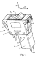
- the electrical switch is a two-pole overcurrent protection switch 1 - below in short: "Circuit breaker 1" - trained. Its made of insulating plastic Switch housing 2 has a rectangular housing opening 3, which by a switching element in the form of a two-armed rocker switch 4 In Fig. 1, the rocker switch 4 is in its on position, in which the Circuits of the two phases of the circuit breaker 1 are closed. The Switch rocker 4 is between its switch-on position and one that interrupts the circuits Switch-off position can be swiveled. On the two narrow sides the switch housing 2 are two resilient housing hooks 5, of which only three housing hooks 5 are visible in FIG. They serve the Attachment of the circuit breaker 1 in a front panel, not shown here.
- the rocker switch 4 acts with a switch lock or a switching mechanism Open and close switching contacts of the circuits and with a magnetic Circuit for electromagnetic undervoltage release together
- the magnetic circuit is part of an undervoltage device 6, the Device housing 7 is mounted in the mounting position on the switch housing 2.
- the basic construction and operation of the circuit breaker 1 is in DE-C-2 928 277.
- the rocker switch 4 is on a housing-fixed Swivel axis 8 pivotally mounted (Fig. 3).
- a coupling cam 10 is attached, which runs transversely to the pivoting plane of the rocker switch 4, a cam track 11 penetrates a latch lever 12 (Fig. 3).
- the latch lever 12 is supported with a support nose 13 arranged at its one free end on a lever arm 14 of a two-armed arm running approximately vertically in the plane of the drawing Release lever 15 from.
- the trigger lever 15 is by means of an axle mount 16 on a housing axis running parallel to the pivot axis 8 pivoted.
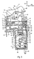
- the rocker switch 4 and the switch lock of the circuit breaker 1 are with the magnetic circuit of the undervoltage device 6 is particularly illustrative in FIG shown fixing slide 24 coupled together.
- the principle of operation the coupling will be described in detail later.
- the fixing slide 24 is in the Installation state within the switch housing 2 and the device housing 7 linearly movable or displaceable.
- the displacement direction 25 runs in the direction its longitudinal extent
- the fixing slide 24 is a plate-like component, the Plate level through the direction of displacement 25 and a transverse to it Transverse direction 26 is spanned.
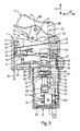
- the fixing slide 24 has one in the transverse direction 26 extending contact shoulder 27, which when the magnetic circuit opens the trigger arm 17 of the trigger lever 15 acts counterclockwise and thereby moves the key switch into its contact opening position (Fig. 4). In this contact opening position of the key switch is the Circuit broken.
- the magnetic circuit contains a plate-shaped magnet armature 28 and a horseshoe-like, d h a U-shaped magnetic core 29.
- the two U-legs of the Magnetic core 29 are connected to each other by a connecting yoke 30 and each have a pole face 31 at their free ends.
- the pole faces 31 are with a closed magnetic circuit directly with a contact surface facing them 32 of the magnet armature 28 contacted.
- Magnetic armatures 28 are at right angles to the direction of displacement 25 in the assembled state the fixing slide 24 is arranged.
- the magnet armature 28 is by a over the support edge 40 in the direction of displacement 25 protruding fixing pin 42 with the fixing slide 24 captive connected.
- the fixing pin 42 which is T-shaped in cross section, has at its end Magnetic armature 28 facing free end extending in the transverse direction 26 Cross bar 43 on.
- the fixing pin passes through 42 in the direction of displacement 25 a central disc longitudinal slot 44 the spring washer 39 and a cross-slot-shaped armature slot 45 of the magnet armature 28.
- the anchor slot 45 is through a first longitudinal slot and one intersecting, shorter longitudinal slot is formed for assembly the cross bar 43 passed through the longer longitudinal slot of the anchor slot 45. Does that stick out?
- the fixing slide 24 is 90 ° rotated so that the fixing pin 42 in the shorter longitudinal slot of the anchor slot 45 snaps into place.
- the crossbar 43 engages behind the slot edge of the anchor slot 45 and is pressed by the spring washer 39 against the supporting edge 40 pressed against the contact surface 32 With the help of the fixing pin 42 are the fixing slide 24, the spring washer 39 and the magnet armature 28 mechanically stable connected.
- the bobbin 37 shown in two parts in FIG. 2 carries one in FIGS. 4-6 schematically illustrated coil 46.
- the two partial bodies 37 'of the coil body 37 each carry two approximately in the direction of movement of the magnet armature 28 extending guide webs 47
- the guide webs 47 are in one piece on the Coil body 37 formed and protrude in the assembled state of the magnetic circuit beyond the pole faces 31 in the direction of drop of the armature 28.
- a boardwalk 47 of the partial body 37 ' is aligned in the transverse direction 26 with a guide web 47 of the second partial body 37 'These two aligned guide webs 47 flank the magnet armature 28 on both sides and thereby force a linear movement of the magnet armature 28 in the direction of displacement 25 around the movement
- a second pair of two guide bars with parallel spacing 47 integrally formed on the coil body 37 The facing the fixing slide 24 Free ends of the guide webs 47 have a stop lug 48 for limitation of the path of the falling magnet armature 28.
- the stop lugs 48 of the two in the transverse direction 26 together aligned guide webs 47 directed towards each other and act on the Face 33 of the falling armature 28 (Fig. 4).
- the division plane of the coil former 37 is also its plane of symmetry, since the two partial bodies 37 'and 37' are identical. Here lies the U-plane of the magnetic core 29 approximately in the parting plane of the coil former 37 a.
- the partial body 37 ' has an opening with the magnetic core 29 facing receiving groove 49. This receiving groove 49 is in the direction of displacement 25 limited by a plurality of groove webs 50.
- the two partial bodies 37 ' are directed towards one another in the transverse direction 26 and take the connecting yoke 30 of the with their grooves 49 Magnetic core 29 approximately form-fitting between them. This is the magnetic core 29 mechanically stably fixed to the bobbin 37
- each partial body 37 ' there are also two transverse to the plane of movement of the fixing slide 24 spaced apart spring hooks 50 are formed.
- the assembled bobbin 37 passes through an insertion opening 51 through along an insertion direction 52 into the cuboid device housing 7 used and locked with the device housing 7.
- the insides of the two transversely to the plane of movement of the fixing slide 24 extending side walls of the device housing 7 two mounting grooves each 53, of which only the one in FIG. 2 due to the perspective representation two mounting grooves 53 of one side wall are visible.
- the two assembly grooves 53 of each side wall run at a parallel distance in the direction of insertion 52. They correspond to corresponding mounting webs 54 of the partial body 37 '.
- the level of these guide webs 54 is through the direction of insertion 52 and Transverse direction 26 spanned. They allow easy assembly and exact Positioning of the electromagnet in the device housing 7.
- the two are parallel to Plane of movement of the fixing slide 24 extending side walls of the device housing 7 each penetrated by two locking holes 55
- These locking holes 55 correspond with appropriately trained and molded on the partial bodies 37 ' Lugs 56 (Fig. 2).
- the spring hooks 50 protrude beyond the insertion opening 51 of the device housing 7 also.
- the insertion opening 51 is in the locked position of the spring hook 50 of the device housing 7 from one arranged in the area of the switch bottom side 23 Cover wall 58 of the switch housing 2 automatically sealed to the outside.
- the fixing slide 24 connected to the magnet armature 28 projects beyond the insertion opening 51 of the device housing 7 also.
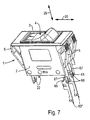
- the coil connections 61 of the coil 46 are via a bridge rectifier 62 with two device connection contacts connected to the voltage to be monitored 63 'or 63 "of the undervoltage device 6 electrically connected (Fig. 1, Fig. 7). It is also in the electrical circuit between the bridge rectifier 62 and the device connection contacts 63 'or 63 "a series resistor 64 used.
- the bridge rectifier 62 is in the assembled state between a resilient clamp arm 59 and the partial body 37 'captively clamped.
- two device connection contacts 63 protrude in the direction of insertion 52 beyond the device housing 7 (Fig. 1,2,3,5,6) and are with the monitoring voltage - not shown here - directly electrically connected.
- two device connection contacts 63 "are complete arranged within the device housing 7 (Fig. 4, Fig. 7).
- this embodiment is the undervoltage device 6 directly with connections of the circuit breaker 1 electrically connected
- the circuit breaker 1 facing Free ends of the device connection contacts 63 "as flat contact tongues 65 educated.
- contact tongues 65 correspond to in the direction of displacement 25 extending contact slots 66 of two switch connection contacts 67 To the two switch connection contacts 67 is not shown here Aids connected to the power supply line, especially screwed on two contact slots 66 are dimensioned such that when attaching the Undervoltage device 6 on the circuit breaker 1, the contact tongues 65 in the contact slots 66 intervene and from these with the necessary electrical contact pressure be clamped.
- the slide free end 60 is of the Switch rocker 4 decoupled and freely movable relative to the rocker switch 4 (Fig. 3)
- the magnet armature 28 is therefore by the spring pressure of the coil spring 34 in the downward direction, i.e. printed in the direction of the rocker switch 4.
- FIG. 8 shows a further embodiment of the circuit breaker 1 with two push buttons 69, 69 'shown as a switching element.
- Functionally identical components are in Fig.8 provided with the same reference numerals as in Fig.1 to Fig.7
- the two Push buttons 69, 69 'for switching the circuit are in the direction of displacement 25 displaceable and form-fit each have a guide recess 70, 70 '.
- the two guide recesses 70, 70 ' are part of one formed on the switch housing shaft-like guide attachment 71.
- Der Guide attachment 71 is also part of the switch housing 2 surrounding mounting panel 72 which 25 in the displacement direction is penetrated by two circular mounting holes 73.
- the mounting holes 73 are used to hold suitable fasteners, e.g. Screws, with whose help the circuit breaker 1 is fixed in place at the installation site.
- the mechanical coupling of the two push buttons 69, 69 'to one another Switching the circuit can in principle in the known from WO-A-9407255 Way.
- the fixing slide 24, not shown in Fig. 8 is with the Push button 69 coupled in such a way that in the off position of the circuit breaker 1 or the push button 69 of the fixing slide 24 the position shown in FIG. 5 occupies.
- the slide free end 60 is preferably in a hood-like Receiving opening of the push button 69 and from this in Direction of the magnetic core 29 is pressurized.
- the embodiment shown is only a single push button as a switching element provided and coupled in a suitable manner with the fixing slide 24.
Landscapes
- Breakers (AREA)
- Tumbler Switches (AREA)
Description
Die Erfindung betrifft einen elektrischen Schalter mit den Merkmalen des Oberbegriffs
des Anspruches 1.The invention relates to an electrical switch with the features of the preamble
of
Derartige Schalter sind aus DE-A-4 341 214 und aus DE-A-3 340 250 bekannt. Diese Schalter wirken mit einem magnetischen Kreis zur elektromagnetischen Unterspannungsauslösung zusammen. Sinkt die überwachte Spannung unter einen bestimmten Wert ab, wird der Magnetkreis geöffnet und infolgedessen ein handbetätigbares Schaltorgan in seine Ausschaltstellung überführt. In dieser Ausschaltstellung ist der Stromkreis des elektrischen Schalters unterbrochen. Das Schaltorgan ist mit dem beweglichen Magnetanker des Magnetkreises derart gekoppelt, daß bei in Ausschaltstellung befindlichem Schaltorgan der Magnetkreis automatisch wieder geschlossen ist. Hierdurch ist der Magnetkreis auch ohne Vorhandensein der erforderlichen Mindestspannung wieder geschlossen. Der Elektromagnet muß deshalb nur die bei geschlossenem Magnetkreis für den Magnetanker erforderliche Haltekraft erzeugen. Diese Haltekraft ist wesentlich kleiner als die Anzugskraft zum Schließen des Magnetkreises bei wieder vorhandener Spannung.Such switches are known from DE-A-4 341 214 and from DE-A-3 340 250. These switches work with a magnetic circuit for electromagnetic Undervoltage release together. If the monitored voltage drops below one determined value, the magnetic circuit is opened and consequently one manually operated switching element transferred to its off position. In this switch-off position the circuit of the electrical switch is interrupted. The Switching element is coupled to the movable magnet armature of the magnetic circuit in such a way that when the switching element is in the switched-off position, the magnetic circuit is automatically closed again. As a result, the magnetic circuit is also without The presence of the required minimum voltage is closed again. The The electromagnet therefore only needs to be closed with a magnetic circuit for the magnet armature generate the required holding force. This holding force is much smaller than the attraction force to close the magnetic circuit when it is back Tension.
Nachteilig bei den vorbekannten Schaltern ist die konstruktiv aufwendige Kopplung zwischen dem Schaltorgan und dem Magnetanker. Die Schaltbewegung des Schaltorgans von seiner Einschaltstellung in seine Ausschaltstellung wird über aufwendige Schwenkhebelkonstruktionen auf den Magnetanker übertragen. Diese Kopplung verkompliziert die Herstellung der für die Unterspannungsauslösung erforderlichen Bauteile und erhöht die Herstellungskosten Außerdem ermöglichen die komplizierten Schwenkhebelkonstruktionen nur eine verhältnismäßig geringe Kraftübertragung zwischen dem Schaltorgan und dem Magnetanker. Bereits geringe Verschleißerscheinungen dieser Schwenkhebel können den ordnungsgemäßen Funktionsablauf bei der Unterspannungsauslösung beeinträchtigen. Um dem entgegenzuwirken, könnten zwar einzelne Kopplungsbauteile stärker dimensioniert werden. Dies hat jedoch einen erhöhten Raumbedarf des Schaltergehäuses und/oder eines für den magnetischen Kreis vorgesehenen Gehäuses zur Folge.A disadvantage of the known switches is the complex coupling between the switching element and the magnet armature. The switching movement of the Switching device from its on position to its off position is over transfer complex rocker arm designs to the magnetic armature. This Coupling complicates the manufacture of the undervoltage release necessary components and increases manufacturing costs also allow the complicated rocker arm designs are only relatively small Power transmission between the switching element and the magnet armature. Already minor Signs of wear and tear of these swivel levers can make the proper Interfering with the operation of the undervoltage release. Around To counteract this, individual coupling components could be dimensioned stronger become. However, this has an increased space requirement for the switch housing and / or a housing provided for the magnetic circuit.
Der Erfindung liegt die Aufgabe zugrunde, einen elektrischen Schalter der eingangs näher genannten Art konstruktions- und sicherheitstechnisch zu verbessern.The invention has for its object an electrical switch of the beginning to improve the type mentioned in terms of construction and safety.
Diese Aufgabe wird durch die Merkmalskombination des Anspruches 1 gelöst
Erfindungsgemaß ist das Schaltorgan mit dem Magnetanker des Magnetkreises
durch einen linearbeweglichen Fixierschieber zum Fixieren des Magnetankers am
Magnetkern in Ausschaltstellung des Schaltorgans gekoppelt. Die Translationsbewegung
des Fixierschiebers ermöglicht einen besonders raumsparenden Aufbau
der zwischen Schaltorgan und Magnetanker erforderlichen Kopplung. Dies
wirkt sich ebenso raumsparend auf die Dimensionierung des Schaltergehäuses
und eines gegebenenfalls vorgesehenen Gehäuses für den Magnetkreis aus
Weiterhin bewirkt der in seiner Verschieberichtung linearbewegliche Fixierschieber,
daß die vom Schaltorgan in Ausschaltstellung auf den Fixierschieber ausgeübten
Kräfte im wesentlichen in Verschieberichtung wirksam direkt auf den Magnetanker
übertragen werden können. Dadurch muß das Schaltorgan nur verhältnismäßig
geringe Kräfte aufbringen, um den Magnetanker in seine angezogene
Stellung am Magnetkern zu verschieben und dort zu fixieren. Vorzugsweise ist
hierbei eine Kontaktfläche des Magnetankers mit einer Polfläche oder mehreren
Polflächen des Magnetkerns direkt kontaktiert. Diese Kontaktierung erfolgt üblicherweise
gegen den Federdruck einer zwischen Magnetanker und Magnetkern
angeordneten und in Abfallrichtung des Magnetankers wirksamen Druckfeder. Die
vom Fixierschieber verursachte gute Kraftübertragung vom Schaltorgan auf den
Magnetanker begünstigt auch einen konstruktionstechnisch einfachen Aufbau des
Schaltorgans und desssen Stabilität während der Betriebsdauer des Schalters.
Vorzugsweise ist der Fixierschieber gehäuseseitig verschiebbar gelagert, wodurch
Fehlbewegungen und fehlerhafte Kraftübertragungen zwischen Schaltorgan und
Magnetanker zuverlässig vermieden werden.This object is achieved by the combination of features of
Die an den Elektromagneten angeschlossene und zu überwachende Spannung ist in einer bevorzugten Ausführungsform die Netzspannung für den Stromkreis des elektrischen Schalters. Grundsätzlich kann der Elektromagnet auch an eine andere Spannung angeschlossen sein. In einer weiteren bevorzugten Ausführungsform ist der Elektromagnet an zwei Phasen eines mehrphasigen Stromsystems angeschlossen. Hierbei wird die Unterspannungs-Einheit vorzugsweise mit einem zweipoligen Schalter kombiniert Der elektrische Schalter ist in einer bevorzugten Ausführungsform als Überstromschutzschalter ausgebildet und weist hierzu je Phase ein entsprechendes Überstrom-Auslöseglied, insbesondere einen auf ein Schaltschloß des Schutzschalters einwirkenden Bimetallstreifen, auf.The voltage connected to the electromagnet and to be monitored is in a preferred embodiment, the mains voltage for the circuit of the electrical switch. In principle, the electromagnet can also be connected to another Voltage must be connected. In a further preferred embodiment the electromagnet is connected to two phases of a multi-phase power system. Here, the undervoltage unit is preferably used with a bipolar switch combined The electrical switch is in a preferred Embodiment designed as an overcurrent protection switch and each has this Phase a corresponding overcurrent trip element, especially one on one Switch lock of the circuit breaker acting bimetal strips.
Die Unterspannungs-Einheit mit dem Magnetkreis kann in das Schaltergehäuse eingebaut sein oder in einem separaten Gehäuse integriert sein, welches durch geeignete Befestigungsmittel mit dem Schaltergehäuse gekoppelt wird.The undervoltage unit with the magnetic circuit can be in the switch housing be installed or integrated in a separate housing, which by suitable fasteners is coupled to the switch housing.
Vorzugsweise sind die Spulenanschlüsse des Elektromagneten über einen Gleichrichter mit den an die zu überwachende Spannung angeschlossenen Kontaktanschlüssen der Unterspannungs-Einheit elektrisch leitend verbunden. Durch den mit Gleichstrom betriebenen Elektromagneten wird das lästige "Brummen" vermieden Eine aufwendige Gestaltung und Bearbeitung der Polflachen des Elektromagneten zur Brummredukion ist deshalb überflüssig. In einer weiteren vorteilhaften Ausgestaltung ist in den elektrischen Kreis zwischen den Spulenanschlüssen des Elektromagneten und den an die zu überwachende Spannung angeschlossenen Kontaktanschlüssen ein Vorwiderstand eingesetzt. Dieser Vorwiderstand reduziert die Leistungsaufnahme der Spulenwicklung und ermöglicht eine geringere Verlustleistung des Elektromagneten im Dauerbetrieb. The coil connections of the electromagnet are preferably via a Rectifier with the contact connections connected to the voltage to be monitored the undervoltage unit electrically connected. By the electromagnet operated with direct current becomes the annoying "hum" avoided A complex design and processing of the pole faces of the Electromagnets for hum reduction are therefore superfluous. In another An advantageous embodiment is in the electrical circuit between the coil connections of the electromagnet and the one connected to the voltage to be monitored A series resistor is used for the contact connections. This series resistor reduces the power consumption of the coil winding and enables a lower power loss of the electromagnet in continuous operation.
Das Schaltorgan ist in einer bevorzugten Ausgestaltung als zweiarmige Schaltwippe ausgebildet, die am Schaltergehäuse schwenkbar gelagert ist. Während der Schwenkung der Schaltwippe in ihre Ausschaltstellung wird deren Schwenkbewegung direkt in eine Translationsbewegung des Fixierschiebers umgewandelt. In einer weiteren Ausfuhrungsform ist das Schaltorgan als ein oder zwei Druckknöpfe ausgebildet, welche zu ihrer Betätigung von dem Benutzer manuell druckbeaufschlagt und dadurch langsverschoben werden. Vorzugsweise verläuft die Längsbewegung des Druckknopfes parallel zur Translationsbewegung des Fixierschiebers, so daß der Druckknopf und der Fixierschieber besonders einfach gekoppelt werden könnenIn a preferred embodiment, the switching element is a two-armed rocker switch formed, which is pivotally mounted on the switch housing. While the pivoting of the rocker switch into its off position becomes its pivoting movement converted directly into a translational movement of the fixing slide. In a further embodiment, the switching element is in the form of one or two push buttons trained, which pressurizes the user to operate them manually and thereby be slowly shifted. Preferably, the Longitudinal movement of the push button parallel to the translational movement of the fixing slide, so that the push button and the fixing slide are particularly easily coupled can be
Die Überfuhrung des Schaltorgans in seine Ausschaltstellung erfolgt bei Freiauslosung durch z.B Überstrom, Unterspannung und bei Handbetätigung Ausgehend von der Ausschaltstellung des Schaltorgans (= unterbrochener Stromkreis) ist der Schalter aus Sicherheitsgründen üblicherweise nicht wieder einschaltbar, wenn die von der Unterspannungs-Einheit überwachte Spannung nicht ausreicht, um den Magnetanker in seiner angezogenen Stellung am Magnetkern zu halten. Bei dem Versuch, das Schaltorgan dennoch in seine Einschaltstellung zu überführen, wird der Magnetkreis geöffnet und die automatische Ablauffolge zum erneuten Ausschalten des Schalters und Schließen des Magnetkreises in Gang gesetzt. Diese automatische Ablauffolge bei versuchter Überführung des Schaltorgans in seine Einschaltstellung trägt dazu bei, daß die Sicherheitsanforderungen an den Schalter erfüllt werden.The switching element is switched to its switch-off position when the trigger is released e.g. overcurrent, undervoltage and manual operation from the switch-off position of the switching element (= interrupted circuit) the switch cannot usually be switched on again for safety reasons, if the voltage monitored by the undervoltage unit is not sufficient, to hold the magnet armature in its tightened position on the magnet core. When trying to move the switching element to its switch-on position anyway, the magnetic circuit is opened and the automatic sequence is repeated Turning off the switch and closing the magnetic circuit started. This automatic sequence when attempting to transfer the switching element to its switch-on position helps to ensure that the safety requirements for the Switches are met.
Vorzugsweise sind der Fixierschieber und das Schaltorgan derart miteinander verbunden, daß der Fixierschieber vom Schaltorgan in dessen Einschaltstellung entkoppelt ist. In diesem Fall sind der Fixierschieber und der Magnetanker gegenüber dem Schaltorgan frei beweglich. Diese freie Beweglichkeit gewährleistet eine zuverlässige Freiauslösung des Schalters bei Unterspannung. Außerdem unterstützt die Entkopplung des Schaltorgans und des Fixierschiebers die vorgenannte Ablauffolge bei dem Versuch, das Schaltorgan trotz Unterspannung in seine Einschaltstellung zu überführen.The fixing slide and the switching element are preferably in such a manner with one another connected that the fixing slide from the switching element in its on position is decoupled. In this case, the fixing slide and the magnet armature are opposite the switching element is freely movable. This free mobility ensures reliable release of the switch in the event of undervoltage. Moreover supports the decoupling of the switching element and the fixing slide the aforementioned Sequence of events when trying to switch the switching element in spite of undervoltage Switch to the on position.
In einer bevorzugten Ausführungsform weist der Fixierschieber eine quer zu seiner Verschieberichtung verlaufende Anlageschulter auf. Bei Unterspannung, d.h. bei abfallendem Magnetanker, wird der Fixerschieber verschoben und beaufschlagt ein mit dem Schaltorgan verbundenes Schaltschloß. Das Schaltschloß ist zum Öffnen und Schließen eines Schaltkontaktes des Stromkreises zwischen einer Kontaktöffnungsstellung und einer Kontaktschließstellung beweglich und überführt beim Öffnen des Schaltkontaktes das Schaltorgan in seine Ausschaltstellung. Auf diese Weise gewährleistet der Fixierschieber bei Unterspannungsauslösung eine technisch einfache automatische Ablauffolge zum Unterbrechen des Stromkreises und erneutem Schließen des Magnetkreises. Zur Auslösung dieser automatischen Ablauffolge, d.h. der Beaufschlagung des Schaltschlosses, sind außer dem Fixierschieber selbst keine weiteren Bauteile notwendig. Dies unterstützt einen raumsparenden und technisch einfachen Aufbau des elektrischen Schalters und der Unterspannungs-Einheit.In a preferred embodiment, the fixing slide has one transverse to it Movement direction extending shoulder on. With undervoltage, i.e. if the magnet armature falls off, the fixer slide is moved and acted upon a switch lock connected to the switching element. The key switch is to open and close a switching contact of the circuit between a Contact opening position and a contact closing position movable and transfers the switching element to its switch-off position when the switching contact is opened. In this way, the fixing slide ensures that undervoltage is triggered a technically simple automatic sequence for interrupting the circuit and closing the magnetic circuit again. For triggering this automatic sequence, i.e. the application of the key switch, apart from the fixing slide itself, no other components are necessary. This supports a space-saving and technically simple construction of the electrical Switch and the undervoltage unit.
In einer bevorzugten Ausführungsform ist zwischen dem Fixierschieber und dem Magnetanker ein Federelement angeordnet. Dessen Federkraft kann fertigungsbedingte Abmessungstoleranzen und -abweichungen des Schaltorgans, des Fixierschiebers und des Magnetankes ausgleichen und gewährleistet dadurch die sichere Funktionsweise des Schalters. Aufgrund der Ausgleichswirkung des Federelementes wird außerdem der Ausschußanteil bei der Herstellung der vorgenannten Bauteile geringer, wodurch auch die Herstellungskosten des elektrischen Schalters und der Unterspannungs-Einheit weiter reduziert werden.In a preferred embodiment is between the fixing slide and the Magnetic armature arranged a spring element. Its spring force can be production-related Dimensional tolerances and deviations of the switching element, the fixing slide and compensate for the magnetic tank, thereby ensuring the safe operation of the switch. Due to the balancing effect of the spring element is also the part of the committee in the production of the aforementioned Components lower, which also reduces the manufacturing costs of the electrical Switch and the undervoltage unit can be further reduced.
Vorzugsweise ist das Ausgleichs-Federelement als bogenartig gewölbte Federscheibe mit einer dem Magnetanker zugewandten Konkavseite ausgebildet. Vorteilhaft stützt sich das Federelement am Magnetanker, insbesondere an dessen dem Fixierschieber zugewandter Stirnfläche, ab und ist hierdurch ohne zusätzliche Hilfsmittel zwischen dem Fixierschieber und dem Magnetanker fixiert Darüber hinaus kann die Federscheibe zwischen Fixierschieber und Magnetanker platzsparend integriert werden und gewährleistet eine besonders wirksame Übertragung der Federkraft auf den Fixierschieber in dessen Verschieberichtung.The compensating spring element is preferably in the form of an arched spring washer formed with a concave side facing the magnet armature. Advantageous the spring element is supported on the magnetic armature, in particular on its the face facing the fixing slide, and is therefore without additional Aids between the fixing slide and the magnetic armature are fixed above In addition, the spring washer between the fixing slide and magnetic armature can be integrated in a space-saving manner and ensures particularly effective transmission the spring force on the fixing slide in its direction of displacement.
In einer vorteilhaften Ausgestaltung ist der Magnetanker mit dem Fixierschieber unverlierbar verbunden. Hierdurch entsteht eine mechanisch besonders stabile antriebsmäßige Kopplung zwischen beiden Bauteilen. Fehlerhafte Funktionsabläufe zum Öffnen und Schließen des Magnetkreises werden deshalb von vornherein vermieden. Die unverlierbare Kopplung ist z.B. durch eine Formschluß- oder eine Stoffschlußverbindung verwirklicht. Die Kopplung kann starr oder beweglich sein.In an advantageous embodiment, the magnet armature with the fixing slide captively connected. This creates a mechanically particularly stable drive coupling between the two components. Faulty functional processes to open and close the magnetic circuit are therefore a priori avoided. The captive coupling is e.g. through a positive or realized a material connection. The coupling can be rigid or movable his.
In einer bevorzugten Ausführungsform ist der Magnetanker etwa quer zu seiner dem Fixierschieber zugewandten Stirnfläche von einem Ankerschlitz durchsetzt. Dieser Ankerschlitz nimmt einen am Fixierschieber angeordneten Fixierzapfen auf. Vorzugsweise ist der Fixierzapfen einstückiger Bestandteil des Fixierschiebers und unterstützt hierdurch eine mechanisch stabile Kopplung zwischen dem Fixierschieber und dem Magnetanker. Vorzugsweise ist der Fixierzapfen nach Art einer Formschlußverbindung mit dem Magnetanker verbunden und vereinfacht hierdurch die Montage der Bauteile. Der Fixierzapfen durchsetzt vom Fixierschieber her den Magnetanker in Richtung der dem Magnetkern zugewandten Kontaktfläche des Magnetankers. Dort hintergreift der Fixierzapfen in einer vorteilhaften Ausgestaltung den Schlitzrand des Ankerschlitzes. Hierzu ist am Fixierzapfen in einer bevorzugten Ausgestaltung ein Quersteg angeformt, der im Montagezustand des Fixierzapfens den kontaktflächenseitigen Schlitzrand des Ankerschlitzes übersteht Dabei sind der Fixerzapfen und sein dazugehöriger Quersteg insbesondere T-formig ausgestaltet. Um den Fixierzapfen besonders stabil am Magnetanker zu koppeln, ist der Ankerschlitz kreuzschlitzförmig mit zwei sich kreuzenden, unterschiedlich langen Längsschlitzen ausgebildet. Die beiden Längsschlitze sind derart dimensioniert, daß der T-formige Fixierzapfen zunächst in den längeren Längsschlitz eingesetzt und mit dem Quersteg durch diesen Längsschlitz hindurchgeführt wird und danach um 90° gedreht in den kürzeren Längsschlitz einrastet. Auf diese Weise ist der Fixerschieber zusätzlich verdrehsicher am Magnetanker gelagert und dadurch noch besser gegen unerwünschte Lageänderungen geschütztIn a preferred embodiment, the magnet armature is approximately transverse to it the end face facing the fixing slide is penetrated by an anchor slot. This anchor slot takes a fixing pin arranged on the fixing slide on. The fixing pin is preferably an integral part of the fixing slide and thereby supports a mechanically stable coupling between the Fixing slide and the magnetic anchor. The fixing pin according to Art a positive connection with the magnet armature connected and simplified thereby the assembly of the components. The fixing pin penetrates the fixing slide forth the magnet armature in the direction of the contact surface facing the magnetic core of the magnet armature. The fixing pin engages there in an advantageous manner Design the slot edge of the anchor slot. For this is on the fixing pin In a preferred embodiment, a crossbar is formed, which is in the assembled state of the fixing pin the slot edge of the anchor slot on the contact surface The fixer pin and its associated crossbar are particularly good T-shaped. To the fixing pin particularly stable on the magnet armature to couple, the anchor slot is cross-shaped with two intersecting, longitudinal slits of different lengths. The two longitudinal slots are dimensioned in such a way that the T-shaped fixing pin is first inserted into the longer longitudinal slot used and with the crossbar through this longitudinal slot is passed through and then rotated by 90 ° into the shorter longitudinal slot snaps into place. In this way, the fixer slide is additionally secured against rotation mounted on the magnet armature and thus even better against unwanted changes in position protected
Ist zwischen dem Fixierschieber und dem Magnetanker das vorgenannte Ausgleichs-Federelement angeordnet, so ist der Fixierzapfen in einer zusätzlichen Funktion als Zentrier- und Fixierelement für dieses Federelement wirksam. Ohne weitere Hilfsmittel ist dieses Federelement am Fixierzapfen unverlierbar gelagert Hierzu ist das Federelement z.B als Schraubenfeder ausgebildet und umgibt den Fixierzapfen mit geringem Radialabstand. Als Federscheibe ausgebildet ist das Federelement quer zur Scheibenebene von einem Schlitz zur Aufnahme des Fixierzapfens durchsetzt und hierdurch ebenfalls verliersicher gelagert.Is the aforementioned compensation spring element between the fixing slide and the magnet armature arranged, the fixing pin is in an additional Function as a centering and fixing element effective for this spring element. Without further aids, this spring element is held captive on the fixing pin For this purpose, the spring element is designed, for example, as a coil spring and surrounds the Locating pin with a small radial distance. This is designed as a spring washer Spring element transversely to the plane of the disc from a slot for receiving the fixing pin enforced and thereby also stored captive.
Um den Raumbedarf der Bauteile des Schalters und der Unterspannungsauslösungs-Einheit weiter zu reduzieren und eine einwandfreie Funktionsweise des Fixierschiebers mit geringen Kopplungskräften zu unterstutzen, verläuft die Verschieberichtung des Fixierschiebers in einer bevorzugten Ausführungsform parallel zur Abfallrichung des Magnetankers. Vorzugsweise liegt die Verschieberichtung des Fixierschiebers gleichzeitig in der Bewegungsebene des Schaltorgans einTo the space requirement of the components of the switch and the undervoltage release unit to further reduce and the proper functioning of the To support the fixing slide with low coupling forces, the direction of displacement is of the fixing slide in a preferred embodiment in parallel for the direction of the magnet armature. The direction of displacement is preferably of the fixing slide at the same time in the plane of movement of the switching element on
Um die Herstellung des Fixierschiebers zu vereinfachen, ist er in einer bevorzugten Ausführungsform plattenartig ausgestaltet, dessen Plattenebene etwa durch die Verschieberichtung und eine quer dazu verlaufende Querrichtung aufgespannt ist. Diese einfache Formgebung erlaubt eine Herstellung des Fixierschiebers als konstengünstigen Massenartikel. Dieser Fixierschieber ist vorteilhaft als Stanzteil aus einem geeigneten Kunststoff oder Metall herstellbar Außerdem ermöglicht die Plattenform des Fixierschiebers eine weitere Miniaturisierung des Schalters und/oder der Unterspannungs-Einheit. In order to simplify the manufacture of the fixing slide, it is a preferred one Embodiment designed plate-like, the plate level about the direction of displacement and a transverse direction extending across it is. This simple shape allows the fixing slide to be manufactured as cheap mass-produced items. This fixing slide is advantageous as a stamped part Can also be made from a suitable plastic or metal the plate shape of the fixing slide further miniaturizes the switch and / or the undervoltage unit.
In einer bevorzugten Ausgestaltung weist der die Spule des Elektromagneten tragende Spulenkorper mindestens zwei über die Polfläche des Magnetkerns in Abfallrichtung des Magnetankers hinausstehende und etwa in Abfallrichtung verlaufende Führungsstege auf. Diese Führungsstege sind einander gegenüberliegend angeordnet und flankieren den Magnetanker seitlich als Bewegungsführung. Hierdurch ist gewährleistet, daß der Magnetanker in Abfallrichtung und in Richtung seiner angezogenen Stellung kontrollierte Bewegungen ausführt Dies trägt dazu bei, daß die miteinander antriebsmäßig gekoppelten Bauteile des elektrischen Schalters und der Unterspannungs-Einheit keine unerwünschten Lageanderungen aufweisen. Außerdem sind diese Fuhrungsstege mittelbar als Bewegungsfuhrung für den mit dem Magnetanker gekoppelten Fixierschieber wirksam. Hierdurch entsteht auch eine einfache Bewegungsführung des Fixierschiebers für den Fall, daß dessen Verschieberichtung und die Bewegungsrichtung des Magnetankers parallel verlaufen. Insbesondere sind die Führungsstege einstückiger Bestandteil des Spulenkörpers, der aus einem geeigneten Kunststoff gespritzt oder gegossen ist.In a preferred embodiment, the one carrying the coil of the electromagnet Coil body at least two over the pole face of the magnetic core in the direction of drop protruding from the magnet armature and running approximately in the direction of the waste Leaders on. These guide bars are opposite one another arranged and flank the magnet armature laterally as a movement guide. Hereby it is guaranteed that the magnet armature in the direction of the fall and in the direction performs controlled movements in its tightened position. This contributes to this in that the components of the electrical drive coupled together Switch and the undervoltage unit no undesirable changes in position exhibit. In addition, these guideways are indirect as a movement guide effective for the locking slide coupled to the magnetic armature. Hereby there is also a simple movement of the fixing slide in case that its direction of displacement and the direction of movement of the magnet armature run in parallel. In particular, the guide webs are an integral part of the bobbin, which is injection molded or cast from a suitable plastic is.
Um die Abfallbewegung des Magnetankers und die Linearbewegung des Fixierschiebers in Verschieberichtung auf ein sinnvolles Maß zu begrenzen, sind an den einander zugewandten Innenseiten der Führungsstege jeweils eine Anschlagnase angeordnet. Diese Anschlagnasen verlaufen quer zur Abfallrichtung des Magnetankers und sind aufeinander zu gerichtet. Vorzugsweise sind diese Anschlagnasen einstückiger Bestandteil der Führungsstege und dadurch fertigungstechnisch einfach herstellbar.About the falling movement of the magnet armature and the linear movement of the fixing slide in the direction of displacement to a reasonable level are to the mutually facing inner sides of the guide webs each have a stop lug arranged. These stop lugs are transverse to the direction of waste of the magnet armature and are directed towards each other. These are preferably Stop lugs are an integral part of the guide bars and are therefore manufactured easy to manufacture.
In einer vorteilhaften Ausgestaltung weist der Elektromagnet des Magnetkreises einen hufeisenartigen oder U-förmigen Magnetkern auf. Die Freienden der beiden U-Schenkel des Magnetkerns weisen jeweils eine Polfläche auf, welche bei geschlossenem Magnetkreis mit der Kontaktfläche des Magnetankers kontaktiert sind. In an advantageous embodiment, the electromagnet of the magnetic circuit a horseshoe-like or U-shaped magnetic core. The freeers of the two U-legs of the magnetic core each have a pole face, which when closed Magnetic circuit contacted with the contact surface of the magnet armature are.
Üblicherweise ist der die Spule des Elektromagneten tragende Spulenkörper im Sinne einer einfachen Montage des Elektromagneten mehrteilig aufgebaut, um den Magnetkern aufnehmen zu können. Hierbei ist es vorteilhaft, den Spulenkörper zweiteilig auszubilden mit der Teilungsebene als Symmetrieebene In diesem Fall ist für den Zusammenbau des Spulenkörpers die Fertigung eines einzigen Bauteiles notwendig. Dies berücksichtigt eine fertigungsgerechte und kostengünstige Herstellung des Elektromagneten.Usually, the coil body carrying the coil of the electromagnet is in the In order to make the electromagnet easy to assemble in several parts to be able to accommodate the magnetic core. Here it is advantageous to use the bobbin to be formed in two parts with the division plane as the symmetry plane in this The case for the assembly of the bobbin is the manufacture of a single one Component necessary. This takes into account a production-oriented and inexpensive Manufacture of the electromagnet.
Durch entsprechende Aussparungen, Nuten und Formgebung des Spulenkörpers wird der Magnetkern am Spulenkörper fixiert. Dabei liegt die U-Ebene des hufeisenartigen Magnetkerns in einer vorteilhaften Ausgestaltung etwa in der Teilungsebene des Spulenkörpers ein. Hierdurch wird der Magnetkern ohne zusätzliche Fixiermittel zwischen den beiden als Klemmbacken wirksamen Teilkörpern des Spulenkörpers klemmfixiert. In einer bevorzugten Ausführungsform werden die beiden Teilkörper z.B durch gegenseitige Verrastung, Verriegelung o.dgl. unverlierbar miteinander verbunden. Diese Verbindung erleichtert die weitere Montage des Elektromagneten und des Magnetkerns als kompakte EinheitThrough appropriate recesses, grooves and shape of the coil body the magnetic core is fixed to the coil body. The U level of the horseshoe lies In an advantageous embodiment, the magnetic core is approximately in the division plane of the bobbin. As a result, the magnetic core without additional Fixing agent between the two partial bodies acting as clamping jaws of the bobbin fixed. In a preferred embodiment the two partial bodies e.g. by mutual locking, locking or the like. captive connected with each other. This connection facilitates further assembly of the electromagnet and the magnetic core as a compact unit
Vorzugsweise ist für die Unterspannungs-Einheit ein separates Gerätegehäuse vorgesehen. Der Spulenkörper des Elektromagneten wird in dieses Gerätegehäuse eingesetzt und dort zweckmäßig lösbar fixiert. Um die Herstellung des Gerätegehäuses zu vereinfachen, trägt der Spulenkörper mehrere Federhaken, welche im Montagezustand über eine Einsetzöffnung des Gerätegehäuses hinausragen und mit entsprechenden Rastaussparungen des Schutzschaltergehäuses korrespondieren. Am Gerätegehäuse müssen deshalb keine weiteren Befestigungsmittel zur Montage am Schaltergehäuse berücksichtigt werden. Das Gerätegehäuse kann deshalb besonders kostensparend z B. als quaderförmiger Aufnahmeschacht o.dgl hergestellt werden. Die Berücksichtigung der Federhaken am Spulenkörper hingegen fällt kostenmäßig nicht so sehr ins Gewicht, da am Spulenkörper ohnehin die Formgestaltung des Magnetkerns und gegebenenfalls die Führungsstege für den Magnetanker berücksichtigt werden müssen.A separate device housing is preferably for the undervoltage unit intended. The coil body of the electromagnet is in this device housing used and conveniently releasably fixed there. To the manufacture of the device housing To simplify, the bobbin carries several spring hooks, which project beyond an insertion opening of the device housing when installed and correspond with corresponding locking recesses in the circuit breaker housing. There is therefore no need for any additional fasteners on the device housing for mounting on the switch housing. The device housing can therefore be particularly cost-saving, for example as a rectangular receiving shaft or the like. Taking into account the spring hooks on the bobbin on the other hand, the cost is not so important because of the coil body anyway the shape of the magnetic core and possibly the Guide bars for the magnet armature must be taken into account.
In Montagestellung des Spulenkörpers und der weiteren Bauteile innerhalb des Gerätegehäuses wird letzteres selbstverständlich nach außen aus Sicherheitsgründen abgedichtet. Hierzu wird vorzugsweise das Schaltergehäuse in einer zusätzlichen Funktion zur Abdichtung verwendet. Hierbei sind die mit den Federhaken zusammenwirkenden Rastaussparungen derart angeordnet, daß eine Außenfläche des Schaltergehauses bei verrasteten Federhaken die Einsetzöffnung des Gerategehäuses automatisch abdeckt. Auf separate Dichtungsmittel zur Abdichtung der Unterspannungs-Einheit im Montagezustand kann deshalb kostensparend verzichtet werden.In the assembly position of the coil body and the other components within the Of course, the latter is made externally for safety reasons sealed. For this purpose, the switch housing is preferably in an additional Sealing function used. Here are the ones with the spring hooks cooperating locking recesses arranged such that an outer surface of the switch housing with the spring hooks locked, the insertion opening of the device housing automatically covers. On separate sealants for sealing The undervoltage unit when assembled can therefore save costs to be dispensed with.
Der Erfindungsgegenstand wird anhand der in den Figuren dargestellten Ausführungsbeispiele naher erläutert. Es zeigen.
- Fig. 1
- eine perspektivische Darstellung eines Überstromschutzschalters mit einem daran befestigten Unterspannungsgerät,
- Fig. 2
- eine Explosionsdarstellung wesentlicher Bauteile des Unterspannungsgeräts gemäß Fig. 1,
- Fig 3
- eine teilweise geschnittene Seitenansicht wesentlicher Bauteile des Überstromschutzschalters und des Unterspannungsgerätes gemäß Fig. 1, mit geschlossenem Magnetkreis und einem Schaltorgan in Einschaltstellung,
- Fig. 4
- die Seitenansicht gemäß Fig. 3 bei geöffnetem Magnetkreis und noch in Einschaltstellung befindlichem Schaltorgan,
- Fig. 5
- die Seitenansicht gemäß Fig. 3 mit dem Schaltorgan in Ausschaltstellung und mit erneut geschlossenem Magnetkreis,
- Fig. 6
- eine Seitenansicht des Unterspannungsgerätes gemäß Pfeilrichtung VI in Fig. 5,
- Fig. 7
- die perspektivische Darstellung des Überstromschutzschalters gemäß Fig. 1 mit einer weiteren Ausführungsform von Gerätekontaktanschlüssen des Unterspannungsgerätes zum elektrischen Anschluß an eine Spannung.
- Fig.8
- eine perspektivische Darstellung eines zwei Druckknöpfe als Schaltorgan enthaltenden Uberstromschutzschalters mit einem daran befestigten Unterspannungsgerät.
- Fig. 1
- 1 shows a perspective illustration of an overcurrent protection switch with an undervoltage device attached to it,
- Fig. 2
- 2 shows an exploded view of essential components of the undervoltage device according to FIG. 1,
- Fig. 3
- 2 shows a partially sectioned side view of essential components of the overcurrent protection switch and the undervoltage device according to FIG. 1, with a closed magnetic circuit and a switching element in the switched-on position,
- Fig. 4
- 3 with the magnetic circuit open and the switching element still in the switched-on position,
- Fig. 5
- 3 with the switching element in the switched-off position and with the magnetic circuit closed again,
- Fig. 6
- 2 shows a side view of the undervoltage device according to arrow direction VI in FIG. 5,
- Fig. 7
- the perspective view of the overcurrent protection switch according to FIG. 1 with a further embodiment of device contact connections of the undervoltage device for electrical connection to a voltage.
- Fig. 8
- a perspective view of an overcurrent protection switch containing two push buttons as a switching element with an undervoltage device attached to it.
Der elektrische Schalter ist als zweipoliger Überstromschutzschalter 1 - nachfolgend
kurz: "Schutzschalter 1" - ausgebildet. Sein aus isolierendem Kunststoff bestehendes
Schaltergehäuse 2 weist eine rechteckige Gehäuseöffnung 3 auf, welche
von einem Schaltorgan in Form einer zweiarmigen Schaltwippe 4 duchsetzt
ist In Fig. 1 befindet sich die Schaltwippe 4 in ihrer Einschaltstellung, in der die
Stromkreise der beiden Phasen des Schutzschalters 1 geschlossen sind. Die
Schaltwippe 4 ist zwischen ihrer Einschaltstellung und einer die Stromkreise unterbrechenden
Ausschaltstellung schwenkbeweglich. An den beiden Schmalseiten
des Schaltergehäuses 2 sind jeweils zwei federnde Gehäusehaken 5, von denen
in Fig 1 lediglich drei Gehäusehaken 5 sichtbar sind, angeformt. Sie dienen der
Befestigung des Schutzschalters 1 in einer hier nicht dargestellten Frontplatte.The electrical switch is a two-pole overcurrent protection switch 1 - below
in short: "
Die Schaltwippe 4 wirkt mit einem Schaltschloß bzw. einer Schaltmechanik zum
Öffnen und Schließen von Schaltkontakten der Stromkreise und mit einem magnetischen
Kreis zur elektromagnetischen Unterspannungsauslösung zusammen
Der magnetische Kreis ist Bestandteil eines Unterspannungsgerätes 6, dessen
Gerätegehäuse 7 in Montagestellung am Schaltergehause 2 befestigt ist.The
Die grundsätzliche Konstruktion und Funktionsweise des Schutzschalters 1 ist in
DE-C-2 928 277 beschrieben. Die Schaltwippe 4 ist an einer gehäusefesten
Schwenkachse 8 schwenkbar gelagert (Fig. 3). An einem der Schaltmechanik zugewandten
Wirkende 9 der Schaltwippe 4 ist ein Kopplungsnocken 10 befestigt,
welcher quer zur Schwenkebene der Schaltwippe 4 verlaufend eine Nockenbahn
11 eines Verklinkungshebels 12 durchsetzt (Fig. 3). Der Verklinkungshebel
12 stützt sich mit einer an seinem einen Freiende angeordneten Stütznase 13
an einem in Zeichenebene etwa vertikal verlaufenden Hebelarm 14 eines zweiarmigen
Auslösehebels 15 ab. Der Auslösehebel 15 ist mittels einer Achsaufnahme
16 an einer parallel zur Schwenkachse 8 verlaufenden Gehäuseachse
schwenkgelagert. Der bezüglich des Verklinkungsarmes 14 etwa rechtwinklig angeordnete
zweite Hebelarm des Auslösehebels, nämlich ein Auslösearm 17, wird
bei Überstrom von einem hier nicht dargestellten Bimetall beaufschlagt, wodurch
der Auslösehebel 15 entgegen dem Uhrzeigersinn geschwenkt wird. Hierdurch
wird der Verklinkungshebel 12 vom Auslösehebel 15 entklinkt und überführt hierdurch
die Schaltwippe 4 in ihre Ausschaltstellung (dies erfolgt prinzipiell in der anhand
von Fig. 4 und Fig. 5 dargestellten Ablauffolge). Der entklinkte Verklinkungshebel
12 beendet den Druck auf eine Kontaktfeder 18, welche entgegen
dem Uhrzeigersinn schwenkt und hierdurch einen an ihrem Freiende befestigten
Schaltkontakt 19 von einem im Schaltergehäuse 2 fixierten Festkontakt 20 (Fig 4,
Fig 5) trennt. Hierdurch ist der Stromkreis des in Zeichenebene von Fig. 3 - Fig 5
dargestellten Poles des Schutzschalters 1 unterbrochen. Die Schaltschlösser beider
Pole des Schutzschalters 1 sind derart miteinander verbunden oder durch ein
einziges Schaltschloß ersetzt, daß die Stromkreise beider Pole immer gleichzeitig
geschlossen oder unterbrochen sind. Mit ihrem dem Schaltkontakt 19 abgewandten
Befestigungsende 21 ist die Kontaktfeder 18 an einer Kontaktzunge 22 angeschweißt.
Diese Kontaktzunge 22 ist im Schaltergehäuse 2 ortsfest fixiert und ragt
über eine Bodenseite 23 des Schaltergehäuses 2 hinaus, um in bekannter Weise
an den dazugehörigen Stromkreis angeschlossen zu werden.The basic construction and operation of the
Die Schaltwippe 4 und das Schaltschloß des Schutzschalters 1 sind mit dem Magnetkreis
des Unterspannungsgerätes 6 über einen in Fig. 2 besonders anschaulich
dargestellten Fixierschieber 24 miteinander gekoppelt. Das Funktionsprinzip
der Kopplung wird im einzelnen später beschrieben. Der Fixierschieber 24 ist im
Montagezustand innerhalb des Schaltergehäuses 2 und des Gerategehäuses 7
linearbeweglich bzw. verschiebbar. Die Verschieberichtung 25 verläuft in Richtung
seiner Längserstreckung Der Fixierschieber 24 ist ein plattenartiges Bauteil, dessen
Plattenebene durch die Verschieberichtung 25 und eine dazu quer verlaufende
Querrichtung 26 aufgespannt ist. Der Fixierschieber 24 weist eine in Querrichtung
26 verlaufende Anlageschulter 27 auf, welche bei sich öffnendem Magnetkreis
den Auslösearm 17 des Auslösehebels 15 entgegen dem Uhrzeigersinn beaufschlagt
und dadurch das Schaltschloss in seine Kontaktöffnungsstellung überführt
(Fig. 4). In dieser Kontaktöffnungsstellung des Schaltschlosses ist der
Stromkreis unterbrochen.The
Der Magnetkreis enthält einen plattenförmigen Magnetanker 28 und einen hufeisenartigen,
d h einen U-förmigen Magnetkern 29. Die beiden U-Schenkel des
Magnetkerns 29 sind durch ein Verbindungsjoch 30 miteinander verbunden und
weisen an ihren Freienden jeweils eine Polfläche 31 auf. Die Polflächen 31 sind
bei geschlossenem Magnetkreis unmittelbar mit einer ihnen zugewandten Kontaktfläche
32 des Magnetankers 28 kontaktiert. Die Kontaktfläche 32 und eine dazu
gegenüberliegende, dem Fixierschieber 24 zugewandte Stirnfläche 33 des
Magnetankers 28 sind im Montagezustand rechtwinklig zur Verschieberichtung 25
des Fixierschiebers 24 angeordnet. Bei geschlossenem Magnetkreis wird die
Kontaktfläche 32 gegen den Federdruck einer Schraubenfeder 34 an den Polflächen
31 gehalten Die mittig zwischen beiden U-Schenkeln des Magnetkerns 29
angeordnete Schraubenfeder 34 umgibt mit ihrem einen axialen Federende formschlüssig
einen Zentrierdorn 35 und beaufschlagt mit ihrem anderen axialen Federende
die Kontaktfläche 32. Der Zentrierdorn 35 ist an der dem Magnetanker
28 zugewandten Oberfläche eines etwa quer zur Verschieberichtung 25 angeordneten
Stützlagers 36 angeformt. Das Stützlager 36 stützt sich im Montagezustand
an einem später noch zu erläuternden Spulenkörper 37 ab. Um das
Stützlager 36 besonders raumsparend zu integrieren, weist es zwei gegenüberliegene
Lagernuten 38 auf, welche im Montagezustand jeweils einen U-Schenkel
des Magnetkerns 29 formschlüssig umgreifen The magnetic circuit contains a plate-shaped
Zwischen dem Fixierschieber 24 und dem Magnetanker 28 ist ein Federelement
in Form einer bogenartig gewölbten Federscheibe 39 angeordnet. Die Federscheibe
39 tangiert mit ihrer Konvexseite eine in Querrichtung 26 verlaufende
Stützkante 40 des Fixierschiebers 24 Im Montagezustand stützt sich die Federscheibe
39 mit ihren beiden in Querrichtung 26 verlaufenden Scheibenkanten 41
an der Stirnfläche 33 des Magnetankers 28 ab. Die in Richtung der Stützkante 40
vorgespannte Federscheibe 39 schafft in Verschieberichtung 25 einen Ausgleich
für fertigungsbedingte Abmessungsunterschiede des Fixierschiebers 24 und des
Magnetankers 28There is a spring element between the fixing
Der Magnetanker 28 ist durch einen über die Stützkante 40 in Verschieberichtung
25 hinausragenden Fixierzapfen 42 mit dem Fixierschieber 24 unverlierbar
verbunden. Der im Querschnitt T-förmige Fixierzapfen 42 weist an seinem dem
Magnetanker 28 zugewandten Freiende einen in Querrichtung 26 verlaufenden
Quersteg 43 auf. Im Montagezustand des Fixierschiebers 24 durchsetzt der Fixierzapfen
42 in Verschieberichtung 25 einen zentralen Scheibenlängsschlitz 44
der Federscheibe 39 und einen kreuzschlitzförmigen Ankerschlitz 45 des Magnetankers
28. Der Ankerschlitz 45 ist durch einen ersten Längsschlitz und einen ihn
kreuzenden, kürzeren Längsschlitz gebildet Zur Montage wird der Quersteg 43
durch den längeren Längsschlitz des Ankerschlitzes 45 hindurchgeführt. Ragt der
Quersteg 43 über die Kontaktfläche 32 hinaus, wird der Fixierschieber 24 um 90°
gedreht, so daß der Fixierzapfen 42 in den kürzeren Längsschlitz des Ankerschlitzes
45 einrastet. Der Quersteg 43 hintergreift den Schlitzrand des Ankerschlitzes
45 und wird durch die gegen die Stützkante 40 drückende Federscheibe 39
gegen die Kontaktfläche 32 gepreßt Mit Hilfe des Fixierzapfens 42 sind der Fixierschieber
24, die Federscheibe 39 und der Magnetanker 28 mechanisch stabil
verbunden.The
Die Verschieberichtung 25 des Fixierschiebers 24 verläuft parallel zur Bewegungsrichtung
(= Abfallrichtung) des Magnetankers 28 und liegt gleichzeitig in der
Bewegungsebene der Schaltwippe 4 ein (Fig. 3 - Fig. 6). The direction of
Der in Fig 2 zweiteilig dargestellte Spulenkörper 37 trägt eine in Fig. 4 - Fig. 6
schematisch dargestellte Spule 46. Die beiden Teilkörper 37' des Spulenkörpes
37 tragen jeweils zwei etwa in Bewegungsrichtung des Magnetankers 28
verlaufende Führungsstege 47 Die Führungsstege 47 sind einstückig an dem
Spulenkörper 37 angeformt und ragen im Montagezustand des Magnetkreises
über die Polflächen 31 in Abfallrichtung des Magnetankers 28 hinaus. Ein Führungssteg
47 des Teilkörpers 37' fluchtet in Querrichtung 26 mit einem Führungssteg
47 des zweiten Teilkörpers 37' Diese beiden fluchtenden Führungsstege
47 flankieren den Magnetanker 28 beidseitig und erzwingen dadurch eine Linearbewegung
des Magnetankers 28 in Verschieberichtung 25 Um die Bewegungsführung
zu verbessern, ist mit Parallelabstand ein zweites Paar zweier Führungsstege
47 am Spulenkörper 37 angeformt. Die dem Fixierschieber 24 zugewandten
Freienden der Führungsstege 47 weisen eine Anschlagnase 48 zur Begrenzung
des Verfahrweges des abfallenden Magnetankers 28 auf. Zu diesem
Zweck sind die Anschlagnasen 48 der beiden in Querrichtung 26 miteinander
fluchtenden Führungsstege 47 aufeinander zu gerichtet und beaufschlagen die
Stirnfläche 33 des abfallenden Magnetankers 28 (Fig. 4).The
Die Teilungsebene des Spulenkörpers 37 ist gleichzeitig dessen Symmetrieebene,
da die beiden Teilkörper 37' und 37' identisch ausgebildet sind. Hierbei liegt
die U-Ebene des Magnetkerns 29 etwa in der Teilungsebene des Spulenkörpers
37 ein. Der Teilkörper 37' weist eine mit seiner Offnung dem Magnetkern 29
zugewandte Aufnahmenut 49 auf. Diese Aufnahmenut 49 ist in Verschieberichtung
25 durch mehrere Nutstege 50 begrenzt. Bei der Montage des Elektromagneten
werden die beiden Teilkörper 37' in Querrichtung 26 aufeinander zu gerichtet
und nehmen mit ihren Aufnahmenuten 49 das Verbindungsjoch 30 des
Magnetkerns 29 etwa formschlüssig zwischen sich auf. Hierdurch ist der Magnetkern
29 am Spulenkörper 37 mechanisch stabil fixiert The division plane of the coil former 37 is also its plane of symmetry,
since the two partial bodies 37 'and 37' are identical. Here lies
the U-plane of the
An jedem Teilkörper 37' sind außerdem zwei quer zur Bewegungsebene des Fixierschiebers
24 voneinander beabstandete Federhaken 50 angeformt. Im Montagezustand
des Spulenkörpers 37 fluchtet jeweils ein Federhaken 50 des ersten
Teilkörpers 37' in Querrichtung 26 mit einem Federhaken 50 des zweiten Teilkörpers
37'. Der zusammengebaute Spulenkörper 37 wird durch eine Einsetzöffnung
51 hindurch entlang einer Einsetzrichtung 52 in das quaderförmige Gerätegehäuse
7 eingesetzt und mit dem Gerätegehäuse 7 verrastet. Zu diesem Zweck
weisen die Innenseiten der beiden quer zur Bewegungsebene des Fixierschiebers
24 verlaufenden Seitenwände des Gerätegehäuses 7 jeweils zwei Montagenuten
53 auf, von denen in Fig 2 aufgrund der Perspektivdarstellung lediglich die
beiden Montagenuten 53 der einen Seitenwand sichtbar sind. Die beiden Montagenuten
53 jeder Seitenwand verlaufen mit Parallelabstand in Einsetzrichtung 52.
Sie korrespondieren mit entsprechenden Montagestegen 54 der Teilkörper 37'.
Die Ebene dieser Führungsstege 54 ist durch die Einsetzrichtung 52 und die
Querrichtung 26 aufgespannt. Sie ermöglichen eine einfache Montage und exakte
Positionierung des Elektromagneten im Gerätegehäuse 7. Zur ortsfesten Postionierung
des Spulenkörpers 37 im Gerätegehäuse 7 sind die beiden parallel zur
Bewegungsebene des Fixierschiebers 24 verlaufenden Seitenwände des Gerätegehäuses
7 von jeweils zwei Rastlöchern 55 durchsetzt Diese Rastlöcher 55 korrespondieren
mit entsprechend ausgebildeten und an den Teilkörpern 37' angeformten
Rastnasen 56 (Fig. 2).On each partial body 37 'there are also two transverse to the plane of movement of the fixing
Im Montagezustand des Spulenkörpers 37 ragen die Federhaken 50 über die Einsetzöffnung
51 des Gerätegehäuses 7 hinaus. Zur montagetechnisch einfachen
Verrastung des Unterspannungsgerätes 6 am Schutzschalter 1 hintergreifen die
Federhaken 50 entsprechende Raststege 57 im Bereich der Schalterbodenseite
23 (Fig. 3 - Fig. 5). In Raststellung der Federhaken 50 ist die Einsetzöffnung 51
des Gerätegehäuses 7 von einer im Bereich der Schalterbodenseite 23 angeordneten
Deckwand 58 des Schaltergehäuses 2 automatisch nach außen abgedichtet.
Der mit dem Magnetanker 28 verbundene Fixierschieber 24 ragt über die Einsetzöffnung
51 des Gerätegehäuses 7 hinaus. Bei der Montage des Gerätegehäuses
7 am Schutzschalter 1 durchsetzt der Fixierschieber 24 in Verschieberichtung
25 eine Wandöffnung der Deckwand 58 und taucht in das Schaltergehäuse 2
ein. Hierbei taucht der Fixierschieber 24 mit einem stangenartig ausgebildeten, in
Verschieberichtung 25 über die Anlageschulter 27 hinausstehenden Schieberfreiende
60 in die Schaltwippe ein (Fig 3 - Fig. 5).When the coil former 37 is in the assembled state, the spring hooks 50 protrude beyond the
Die Spulenanschlüsse 61 der Spule 46 sind über einen Bruckengleichrichter 62
mit zwei an die zu überwachende Spannung angeschlossenen Gerateanschlußkontakten
63' bzw. 63" des Unterspannungsgerätes 6 elektrisch leitend verbunden
(Fig. 1, Fig. 7). Außerdem ist in den elektrischen Kreis zwischen dem Brükkengleichrichter
62 und den Geräteanschlußkontakten 63' bzw. 63" ein Vorwiderstand
64 eingesetzt. Der Brückengleichrichter 62 ist im Montagezustand zwischen
einem am Teilkörper 37' angeformten, federelastischen Klemmausleger 59 und
dem Teilkörper 37' unverlierbar klemmfixiert.The
Für die Geräteanschlußkontakte sind zwei Ausfuhrungsformen vorgesehen. In
einer ersten Ausführungsform ragen zwei Geräteanschlußkontakte 63' in Einsetzrichtung
52 über das Gerategehäuse 7 hinaus (Fig. 1,2,3,5,6) und sind mit der zu
überwachenden Spannung - hier nicht dargestellt - direkt elektrisch verbunden. In
einer zweiten Ausführungsform sind zwei Geräteanschlußkontakte 63" vollständig
innerhalb des Gerätegehäuses 7 angeordnet (Fig. 4, Fig. 7). Bei dieser Ausführungsform
ist das Unterspannungsgerät 6 direkt mit Anschlüssen des Schutzschalters
1 elektrisch verbunden Hierzu sind die dem Schutzschalter 1 zugewandten
Freienden der Geräteanschlußkontakte 63" als flache Kontaktzungen 65
ausgebildet. Diese Kontaktzungen 65 korrespondieren mit in Verschieberichtung
25 verlaufenden Kontaktschlitzen 66 zweier Schalteranschlußkontakte 67
An die beiden Schalteranschlußkontakte 67 wird durch hier nicht näher dargestellte
Hilfsmittel die Netzzuleitung angeschlossen, insbesondere angeschraubt Die
beiden Kontaktschlitze 66 sind derart dimensioniert, daß bei der Befestigung des
Unterspannungsgerätes 6 am Schutzschalter 1 die Kontaktzungen 65 in die Kontaktschlitze
66 eingreifen und von diesen mit dem nötigen elektrischen Kontaktdruck
klemmfixiert werden.Two embodiments are provided for the device connection contacts. In
In a first embodiment, two
Das Funktionsprinzip des mit dem Unterspannungsgerät 6 kombinierten Schutzschalters
1 wird nachfolgend erläutert: Bei Überstrom wird das Schaltschloß bzw
die Schaltmechanik des Schutzschalters 1 in eine den Stromkreis unterbrechende
Kontaktöffnungsstellung und die Schaltwippe 4 in ihre Ausschaltstellung überführt
(Fig. 5). Die in ihre Ausschaltstellung überführte Schaltwippe 4 beaufschlagt mit
ihrer dem Benutzer zugewandten Betätigungsseite 68 das Schieberfreiende 60 in
Verschieberichtung 25. Hierdurch wird der Magnetanker 28 am Magnetkern 29
gehalten (= geschlossener Magnetkreis), unabhängig davon, wie groß die an den
Geräteanschlußkontakten 63' bzw. 63" angelegte Spannung ist (Fig. 5).The principle of operation of the circuit breaker combined with the
In Einschaltstellung der Schaltwippe 4 ist das Schieberfreiende 60 von der
Schaltwippe 4 entkoppelt und gegenüber der Schaltwippe 4 frei beweglich
(Fig. 3) In diesem Fall ist die Positionierung des Fixierschiebers 24 ausschließlich
von der Stellung des Magnetankers 28 abhängig. Dieser wird ausschließlich durch
die an den Geräteanschlußkontakten 63' bzw. 63" anliegende Spannung am Magnetkern
29 gehalten (= geschlossener Magnetkreis gemäß Fig. 3). Sinkt die
Spannung unter einen bestimmten Wert ab, reicht die Haltekraft des Elektromagneten
nicht aus, um den Magnetanker 28 in seiner angezogenen Stellung zu
halten. Der Magnetanker 28 wird deshalb durch den Federdruck der Schraubenfeder
34 in Abfallrichtung, d.h. in Richtung der Schaltwippe 4 gedruckt. Der mit
dem Magnetanker 28 gekoppelte Fixierschieber 24 wird in Verschieberichtung 25
zur Betätigungsseite 68 der Schaltwippe 4 hin verschoben (Fig. 4). Hierbei beaufschlagt
die Anlageschulter 27 des Fixierschiebers 24 den Auslösehebel 15 entgegen
dem Uhrzeigersinn, wodurch das Schaltschloß - wie bereits beschrieben - in
die Kontaktöffnungsstellung überführt wird. Die hierbei mit Hilfe einer hier nicht
dargestellten Drehfeder in ihre Ausschaltstellung schwenkende Schaltwippe 4 beaufschlagt
mit ihrer Betätigungsseite 68 automatisch den Fixierschieber 24 und
verschiebt ihn in Verschieberichtung 25 hin zum Magnetkern 29 (Fig. 5). Der Magnetkreis
wird deshalb in Ausschaltstellung der Schaltwippe 4 immer automatisch
geschlossen, auch wenn die zum Halten des Magnetankers 28 am Magnetkern 29
erforderliche Spannung an den Geräteanschlußkontakten 63 bzw. 63" noch nicht
erneut anliegt.In the switched-on position of the
Liegt die erforderliche Spannung wieder an, dann ist der Magnetkreis beim erneuten
Einschalten des Schutzschalters 1 (= Überführung der Schaltwippe 4 in ihre
Einschaltstellung) bereits geschlossen. Der Elektromagnet muß deshalb nur die
erforderliche Haltekraft für den Magnetanker 28 erzeugen. Liegt die erforderliche
Spannung hingegen noch nicht wieder an, so wird der Magnetkreis bei dem Versuch,
die Schaltwippe 4 in ihre Einschaltstellung zu überfuhren, automatisch geoffnet.
Hierdurch beaufschlagt die Anlageschulter 27 den Auslösehebel 17, so
daß das Schaltschloß in seine Kontaktöffnungsstellung gezwungen wird. Die
Schaltwippe 4 kann deshalb nicht in ihre Einschaltstellung überführt und der
Schutzschalter 1 nicht eingeschaltet werden, solange die erforderliche Spannung
an den Geräteanschlußkontakten 63' bzw. 63" nicht wieder anliegt.If the required voltage is present again, the magnetic circuit is in the process of renewed
Switch on the circuit breaker 1 (= transfer of the
In Fig. 8 ist eine weitere Ausführungsform des Schutzschalters 1 mit zwei Druckknöpfen
69, 69' als Schaltorgan dargestellt. Funktionsgleiche Bauteile sind in
Fig.8 mit den gleichen Bezugszeichen wie in Fig.1 bis Fig.7 versehen Die beiden
Druckknöpfe 69, 69' zum Schalten des Stromkreises sind in Verschieberichtung
25 verschiebbar und durchsetzen formschlüssig jeweils eine Führungsaussparung
70, 70'. Die beiden Führungsaussparungen 70, 70' sind Bestandteil eines
am Schaltergehäuse angeformten schachtartigen Führungsaufsatzes 71. Der
Führungsaufsatz 71 ist von einer ebenfalls einen Bestandteil des Schaltergehäuses
2 bildenden Montageblende 72 umgeben, welche in Verschieberichtung 25
von zwei kreisrunden Montagelöchern 73 durchsetzt ist. Die Montagelöcher 73
dienen der Aufnahme von geeigneten Befestigungsmitteln, z.B. Schrauben, mit
deren Hilfe der Schutzschalter 1 am Montageort ortsfest fixiert wird. 8 shows a further embodiment of the
Die mechanische Kopplung der beiden Druckknöpfe 69,69' miteinander zum
Schalten des Stromkreises kann prinzipiell in der aus WO-A-9407255 bekannten
Weise erfolgen. Der in Fig. 8 nicht dargestellte Fixierschieber 24 ist mit dem
Druckknopf 69 derart gekoppelt, daß in Ausschaltstellung des Schutzschalters 1
bzw. des Druckknopfes 69 der Fixierschieber 24 die aus Fig 5 ersichtliche Stellung
einnimmt. Hierbei liegt das Schieberfreiende 60 vorzugsweise in einer haubenartigen
Aufnahmeöffnung des Druckknopfes 69 ein und wird von diesem in
Richtung des Magnetkerns 29 druckbeaufschlagt. In einer weiteren, hier nicht
dargestellten Ausführungsform ist lediglich ein einziger Druckknopf als Schaltorgan
vorgesehen und in geeigneter Weise mit dem Fixierschieber 24 gekoppelt. The mechanical coupling of the two
Bezugszeichenliste
- 1
- Überstrom schutzschalter
- 2
- Schaltergehause
- 3
- Gehäuseöffnung
- 4
- Schaltwippe
- 5
- Gehäusehaken
- 6
- Unterspannungsgerät
- 7
- Gerätegehäuse
- 8
- Schwenkachse
- 9
- Wirkende
- 10
- Kopplungsnocken
- 11
- Nockenbahn
- 12
- Verklinkungshebel
- 13
- Stütznase
- 14
- Verklinkungsarm
- 15
- Auslösehebel
- 16
- Achsaufnahme
- 17
- Auslösearm
- 18
- Kontaktfeder
- 19
- Schaltkontakt
- 20
- Festkontakt
- 21
- Befestigungsende
- 22
- Kontaktzunge
- 23
- Schalterbodenseite
- 24
- Fixierschieber
- 25
- Verschieberichtung
- 26
- Querrichtung
- 27
- Anlageschulter
- 28
- Magnetanker
- 29
- Magnetkern
- 30
- Verbindungsjoch
- 31
- Polfläche
- 32
- Kontaktfläche
- 33
- Stirnfläche
- 34
- Schraubenfeder
- 35
- Zentrierdorn
- 36
- Stutzlager
- 37
- Spulenkörper
- 37'
- Teilkörper
- 38
- Lagernut
- 39
- Federscheibe
- 40
- Stutzkante
- 41
- Scheibenkante
- 42
- Fixierzapfen
- 43
- Quersteg
- 44
- Scheibenlängsschlitz
- 45
- Ankerschlitz
- 46
- Spule
- 47
- Führungssteg
- 48
- Anschlagnase
- 49
- Aufnahmenut
- 50
- Federhaken
- 51
- Einsetzöffnung
- 52
- Einsetzrichtung
- 53
- Montagenut
- 54
- Montagesteg
- 55
- Rastloch
- 56
- Rastnase
- 57
- Raststeg
- 58
- Deckwand
- 59
- Klemmausleger
- 60
- Schieberfreiende
- 61
- Spulenanschluß
- 62
- Brückengleichrichter
- 63',63"
- Geräteanschlußkontakt
- 64
- Vorwiderstand
- 65
- 5 Kontaktzunge
- 66
- Kontaktschlitz
- 67
- Schalteranschlußkontakt
- 68
- Betätigungsseite
- 69,69'
- Druckknopf
- 70.70'
- Führungsaussparung
- 71
- Führungsaufsatz
- 72
- Montageblende
- 73
- Montageloch
- 1
- Overcurrent circuit breaker
- 2
- Counter case
- 3rd
- Housing opening
- 4th
- Rocker switch
- 5
- Case hook
- 6
- Undervoltage device
- 7
- Device housing
- 8th
- Swivel axis
- 9
- Actors
- 10
- Coupling cams
- 11
- Cam track
- 12th
- Latch lever
- 13
- Support nose
- 14
- Low latching
- 15
- Release lever
- 16
- Axle support
- 17th
- Trigger arm
- 18th
- Contact spring
- 19th
- Switch contact
- 20th
- Fixed contact
- 21
- Fastening end
- 22
- Tongue
- 23
- Switch bottom side
- 24th
- Fixing slide
- 25th
- Direction of displacement
- 26
- Cross direction
- 27
- Investment shoulder
- 28
- Magnetic anchor
- 29
- Magnetic core
- 30th
- Connecting yoke
- 31
- Pole face
- 32
- Contact area
- 33
- Face
- 34
- Coil spring
- 35
- Centering mandrel
- 36
- Support bearing
- 37
- Bobbin
- 37 '
- Partial body
- 38
- Bearing groove
- 39
- Spring washer
- 40
- Support edge
- 41
- Edge of the pane
- 42
- Fixing pin
- 43
- Crossbar
- 44
- Longitudinal slit
- 45
- Anchor slot
- 46
- Kitchen sink
- 47
- Boardwalk
- 48
- Stop nose
- 49
- Groove
- 50
- Spring hook
- 51
- Insertion opening
- 52
- Direction of insertion
- 53
- Mounting groove
- 54
- Assembly bridge
- 55
- Rest hole
- 56
- Latch
- 57
- Rest bridge
- 58
- Top wall
- 59
- Clamp arm
- 60
- Slide-free end
- 61
- Coil connection
- 62
- Bridge Rectifiers
- 63 ', 63 "
- Device connection contact
- 64
- Series resistor
- 65
- 5 contact tongue
- 66
- Contact slot
- 67
- Switch connection contact
- 68
- Actuation side
- 69.69 '
- Push button
- 70.70 '
- Guide recess
- 71
- Leadership essay
- 72
- Mounting panel
- 73
- Mounting hole
Claims (16)
- Electrical switch (1) having a switching element (4, 69), which moves between a switched-on and a switched-off position, for switching a circuit, and having a magnetic circuit (28, 29) for electromagnetic undervoltage tripping, with the switching element (4, 69) moving to its switched-off position in the event of an undervoltage in the opening magnetic circuit (28, 29), and with the switching element (4, 69) which has moved to its switched-off position closing the magnetic circuit (28, 29) once again,
characterized by
a linear-moving fixing slide (24), which couples the switching element (4, 69) to the magnet armature (28), for fixing the magnet armature (28) on the magnet core (29) when the switching element (4, 69) is in the switched-off position. - Switch according to Claim 1,
characterized in that the fixing slide (24) is decoupled from the switching element (4, 69) when the latter is in the switched-on position. - Switch according to Claim 1 or 2,
characterized in that the fixing slide (24) has a contact shoulder (27) which runs transversely with respect to the movement direction (25) and, when the magnet armature (28) trips out, acts on a switching mechanism (12, 15) which is connected to the switching element (4, 69), in order to open a switching contact (19) in the circuit and in order to move the switching element (4, 69) to its switched-off position. - Switch according to one or more of the preceding claims,
characterized by
a spring element (39), which is arranged between the fixing slide (24) and the magnet armature (28), for positioning the fixing slide (24) between the switching element (4, 69) and the magnet armature (28). - Switch according to Claim 4,
characterized by
a spring washer (39), which is supported on the magnet armature (28), is domed in the form of a curve, and whose concave side faces the magnet armature (28). - Switch according to one or more of the preceding claims,
characterized in that the magnet armature (28) is connected in a captive manner to the fixing slide (24). - Switch according to Claim 6, characterized in that the magnet armature (28) has an armature slot (45) for holding a fixing pin (42), which is arranged on the fixing slide (24) and engages behind a slot edge of the armature slot (45).
- Switch according to one or more of the preceding claims,
characterized in that the device (25) for moving the fixing slide (24) runs parallel to the tripping direction of the magnet armature (28) and/or lies in the movement plane of the switching element (4, 69). - Switch according to one or more of the preceding claims.
characterized by
a fixing slide (24) in the form of a plate. - Switch according to one or more of the preceding claims,
characterized in that the coil former (37) to which the coil (40) of the electromagnet is fitted has at least two guide webs (47) which project beyond the pole surface (31) of the magnet core (29) in the tripping direction of the magnet armature (28) and, mutually opposite one another, flank the magnet armature (28) as a movement guide at the sides. - Switch according to Claim 10,
characterized in that the guide webs (47) are each fitted with a stop tab (48), which stop tabs (48) point towards one another, transversely with respect to the tripping direction. - Switch according to one or more of the preceding claims,
characterized in that the magnet armature (28) makes contact with the two pole surfaces (31) of a horseshoe-like magnet core (29) in order to close the magnetic circuit. - Switch according to one or more of the preceding claims,
characterized in that the coil former (37) to which the coil (40) of the electromagnet is fitted is split in two with the dividing plane being the plane of symmetry. - Switch according to Claims 12 and 13,
characterized in that the U-plane of the horseshoe-like magnet core (29) lies approximately in the dividing plane of the coil former (37). - Switch according to one or more of the preceding claims,
characterizedin that the coil former (37) to which the coil (40) of the electromagnet is fitted is inserted into an appliance housing (7) and is fixed there, andin that the coil former (37) is fitted with spring hooks (50) which project through an insertion opening (51) in the appliance housing (7) in the assembled state, and correspond with corresponding latching cut-outs (57) in the switch housing (2). - Switch according to Claim 15,
characterized in that the insertion opening (51) in the appliance housing (7) is sealed externally by a cover wall (58) of the switch housing (2) when the spring hooks (50) are in the latched position.
Priority Applications (1)
| Application Number | Priority Date | Filing Date | Title |
|---|---|---|---|
| DE29724577U DE29724577U1 (en) | 1997-04-17 | 1997-04-17 | Electrical switch with undervoltage release |
Applications Claiming Priority (2)
| Application Number | Priority Date | Filing Date | Title |
|---|---|---|---|
| DE29607027 | 1996-04-18 | ||
| DE29607027U | 1996-04-18 |
Publications (3)
| Publication Number | Publication Date |
|---|---|
| EP0802552A2 EP0802552A2 (en) | 1997-10-22 |
| EP0802552A3 EP0802552A3 (en) | 1999-03-10 |
| EP0802552B1 true EP0802552B1 (en) | 2001-11-21 |
Family
ID=8022750
Family Applications (1)
| Application Number | Title | Priority Date | Filing Date |
|---|---|---|---|
| EP97106350A Expired - Lifetime EP0802552B1 (en) | 1996-04-18 | 1997-04-17 | Electrical switch with undervoltage release |
Country Status (4)
| Country | Link |
|---|---|
| US (1) | US5834996A (en) |
| EP (1) | EP0802552B1 (en) |
| JP (1) | JP3754796B2 (en) |
| DE (1) | DE59705433D1 (en) |
Cited By (4)
| Publication number | Priority date | Publication date | Assignee | Title |
|---|---|---|---|---|
| US7722444B2 (en) | 2005-05-13 | 2010-05-25 | Black & Decker Inc. | Angle grinder |
| DE102009025514A1 (en) | 2009-06-19 | 2010-12-30 | Ellenberger & Poensgen Gmbh | Control method for triggering an electronic circuit breaker |
| DE202010018176U1 (en) | 2009-06-19 | 2014-07-08 | Ellenberger & Poensgen Gmbh | Electronic circuit breaker |
| US10818450B2 (en) | 2017-06-14 | 2020-10-27 | Black & Decker Inc. | Paddle switch |
Families Citing this family (4)
| Publication number | Priority date | Publication date | Assignee | Title |
|---|---|---|---|---|
| DE19919331A1 (en) * | 1999-04-28 | 2000-11-02 | Ellenberger & Poensgen | Undervoltage release |
| US6613995B1 (en) | 2002-01-04 | 2003-09-02 | Reliance Controls Corporation | Switch having stabilizing protrusions to facilitate mounting thereof |
| WO2011015230A1 (en) * | 2009-08-04 | 2011-02-10 | Abb Ab | A low-voltage contactor |
| USD938369S1 (en) * | 2019-10-21 | 2021-12-14 | Ellenberger & Poensgen Gmbh | Combined electrical switch with mounting plate |
Family Cites Families (12)
| Publication number | Priority date | Publication date | Assignee | Title |
|---|---|---|---|---|
| US4019097A (en) * | 1974-12-10 | 1977-04-19 | Westinghouse Electric Corporation | Circuit breaker with solid state passive overcurrent sensing device |
| US4034266A (en) * | 1975-08-29 | 1977-07-05 | Westinghouse Electric Corporation | Electric wall receptacle with ground fault protection |
| CH614069A5 (en) * | 1977-03-31 | 1979-10-31 | Weber Ag Fab Elektro | |
| DE2928277C2 (en) * | 1979-07-13 | 1983-12-01 | Ellenberger & Poensgen Gmbh, 8503 Altdorf | Combinable two-pole overcurrent circuit breaker |
| DE3114717C2 (en) * | 1981-04-11 | 1987-04-30 | Licentia Patent-Verwaltungs-Gmbh, 6000 Frankfurt | Undervoltage release for a circuit breaker |
| DE3424089A1 (en) * | 1983-08-19 | 1985-03-07 | Weber AG Fabrik elektrotechnischer Artikel und Apparate, Emmenbrücke | PUSH BUTTON ACTUATED OVERCURRENT SWITCH |
| DE3340250A1 (en) * | 1983-11-08 | 1985-05-15 | Heinrich Kopp Gmbh & Co Kg, 8756 Kahl | Earth-leakage current protection circuit breaker (section) having a reduced-voltage trip device |
| DE4003744A1 (en) * | 1990-02-08 | 1991-08-14 | Klinger & Born Gmbh | Rotary switch with automatic cut=out upon voltage loss - has spring loaded return lever holding armature in self-holding position |
| CH680174A5 (en) * | 1990-05-23 | 1992-06-30 | Weber Ag | |
| DE9321289U1 (en) * | 1992-09-19 | 1997-01-09 | Ellenberger & Poensgen GmbH, 90518 Altdorf | Push button operated circuit breaker |
| DE9421886U1 (en) * | 1993-03-17 | 1997-02-06 | Ellenberger & Poensgen | Device switch with integrated overcurrent protection |
| DE4341214C2 (en) * | 1993-12-03 | 1996-11-07 | Kloeckner Moeller Gmbh | Tripping unit for circuit breakers or circuit breakers |
-
1997
- 1997-04-15 US US08/843,398 patent/US5834996A/en not_active Expired - Lifetime
- 1997-04-17 EP EP97106350A patent/EP0802552B1/en not_active Expired - Lifetime
- 1997-04-17 DE DE59705433T patent/DE59705433D1/en not_active Expired - Lifetime
- 1997-04-18 JP JP10212397A patent/JP3754796B2/en not_active Expired - Fee Related
Cited By (6)
| Publication number | Priority date | Publication date | Assignee | Title |
|---|---|---|---|---|
| US7722444B2 (en) | 2005-05-13 | 2010-05-25 | Black & Decker Inc. | Angle grinder |
| US8087976B2 (en) | 2005-05-13 | 2012-01-03 | Black & Decker Inc. | Trigger assembly for angle grinder |
| US8087977B2 (en) | 2005-05-13 | 2012-01-03 | Black & Decker Inc. | Angle grinder |
| DE102009025514A1 (en) | 2009-06-19 | 2010-12-30 | Ellenberger & Poensgen Gmbh | Control method for triggering an electronic circuit breaker |
| DE202010018176U1 (en) | 2009-06-19 | 2014-07-08 | Ellenberger & Poensgen Gmbh | Electronic circuit breaker |
| US10818450B2 (en) | 2017-06-14 | 2020-10-27 | Black & Decker Inc. | Paddle switch |
Also Published As
| Publication number | Publication date |
|---|---|
| US5834996A (en) | 1998-11-10 |
| EP0802552A2 (en) | 1997-10-22 |
| JPH1040779A (en) | 1998-02-13 |
| JP3754796B2 (en) | 2006-03-15 |
| EP0802552A3 (en) | 1999-03-10 |
| DE59705433D1 (en) | 2002-01-03 |
Similar Documents
| Publication | Publication Date | Title |
|---|---|---|
| DE69808446T2 (en) | TRIP MECHANISM FOR OVERLOAD RELAY | |
| EP0543208B1 (en) | Protective circuit-breaker with rocker | |
| EP0317660B1 (en) | Contactor | |
| EP0185107B1 (en) | Motor protection switch | |
| DE3874168T2 (en) | REMOTE ON / OFF CIRCUIT BREAKER. | |
| EP0563774A2 (en) | Protective circuit breaker with remote control | |
| DE1256300B (en) | Contactor | |
| EP0033841B1 (en) | Relay | |
| DE3880659T2 (en) | Protection device for electrical systems. | |
| EP0802552B1 (en) | Electrical switch with undervoltage release | |
| DE3713537A1 (en) | REVERSE SWITCHING DEVICE WITH OVERCURRENT PROTECTION | |
| DE69218025T2 (en) | Electromechanical switching device with frontal additional component | |
| DE3539976A1 (en) | SWITCH-OFF DEVICE WITH REMOTE CONTROL OF THE OPENING AND CLOSING OF YOUR CIRCLES | |
| WO1999054897A1 (en) | Switching device with interrupter chamber module | |
| DE1465705B1 (en) | Electrical snap switch with lever | |
| DE4233918B4 (en) | Electrical switch with current monitoring | |
| EP0036432B2 (en) | Contactor, particularly a power or control or starter contactor | |
| DE69022333T2 (en) | Load switches or modular switches equipped with a separating element. | |
| DE4213729C2 (en) | Circuit breakers, in particular motor protection switches | |
| DE721862C (en) | Circuit breakers, in particular circuit breakers | |
| EP0188482B1 (en) | Switch latch | |
| DE69509704T2 (en) | Switch protection with locking device for rail mounting | |
| EP0145946B1 (en) | Line-protecting cut-out | |
| DE29724577U1 (en) | Electrical switch with undervoltage release | |
| EP0011201B1 (en) | Electromagnetic switchgear |
Legal Events
| Date | Code | Title | Description |
|---|---|---|---|
| PUAI | Public reference made under article 153(3) epc to a published international application that has entered the european phase |
Free format text: ORIGINAL CODE: 0009012 |
|
| AK | Designated contracting states |
Kind code of ref document: A2 Designated state(s): CH DE FR GB IT LI |
|
| PUAL | Search report despatched |
Free format text: ORIGINAL CODE: 0009013 |
|
| AK | Designated contracting states |
Kind code of ref document: A3 Designated state(s): CH DE FR GB IT LI |
|
| 17P | Request for examination filed |
Effective date: 19990408 |
|
| GRAG | Despatch of communication of intention to grant |
Free format text: ORIGINAL CODE: EPIDOS AGRA |
|
| 17Q | First examination report despatched |
Effective date: 20010531 |
|
| GRAG | Despatch of communication of intention to grant |
Free format text: ORIGINAL CODE: EPIDOS AGRA |
|
| GRAH | Despatch of communication of intention to grant a patent |
Free format text: ORIGINAL CODE: EPIDOS IGRA |
|
| GRAH | Despatch of communication of intention to grant a patent |
Free format text: ORIGINAL CODE: EPIDOS IGRA |
|
| GRAA | (expected) grant |
Free format text: ORIGINAL CODE: 0009210 |
|
| AK | Designated contracting states |
Kind code of ref document: B1 Designated state(s): CH DE FR GB IT LI |
|
| REG | Reference to a national code |
Ref country code: CH Ref legal event code: EP |
|
| REG | Reference to a national code |
Ref country code: CH Ref legal event code: NV Representative=s name: E. BLUM & CO. PATENTANWAELTE |
|
| REG | Reference to a national code |
Ref country code: GB Ref legal event code: IF02 |
|
| REF | Corresponds to: |
Ref document number: 59705433 Country of ref document: DE Date of ref document: 20020103 |
|
| GBT | Gb: translation of ep patent filed (gb section 77(6)(a)/1977) |
Effective date: 20020216 |
|
| ET | Fr: translation filed | ||
| PLBE | No opposition filed within time limit |
Free format text: ORIGINAL CODE: 0009261 |
|
| STAA | Information on the status of an ep patent application or granted ep patent |
Free format text: STATUS: NO OPPOSITION FILED WITHIN TIME LIMIT |
|
| 26N | No opposition filed | ||
| REG | Reference to a national code |
Ref country code: CH Ref legal event code: PFA Owner name: ELLENBERGER & POENSGEN GMBH Free format text: ELLENBERGER & POENSGEN GMBH#INDUSTRIESTRASSE 2-8#D-90518 ALTDORF (DE) -TRANSFER TO- ELLENBERGER & POENSGEN GMBH#INDUSTRIESTRASSE 2-8#D-90518 ALTDORF (DE) |
|
| REG | Reference to a national code |
Ref country code: FR Ref legal event code: PLFP Year of fee payment: 19 |
|
| PGFP | Annual fee paid to national office [announced via postgrant information from national office to epo] |
Ref country code: GB Payment date: 20150423 Year of fee payment: 19 Ref country code: CH Payment date: 20150422 Year of fee payment: 19 Ref country code: DE Payment date: 20150428 Year of fee payment: 19 |
|
| PGFP | Annual fee paid to national office [announced via postgrant information from national office to epo] |
Ref country code: IT Payment date: 20150423 Year of fee payment: 19 Ref country code: FR Payment date: 20150422 Year of fee payment: 19 |
|
| REG | Reference to a national code |
Ref country code: DE Ref legal event code: R119 Ref document number: 59705433 Country of ref document: DE |
|
| REG | Reference to a national code |
Ref country code: CH Ref legal event code: PL |
|
| GBPC | Gb: european patent ceased through non-payment of renewal fee |
Effective date: 20160417 |
|
| REG | Reference to a national code |
Ref country code: FR Ref legal event code: ST Effective date: 20161230 |
|
| PG25 | Lapsed in a contracting state [announced via postgrant information from national office to epo] |
Ref country code: LI Free format text: LAPSE BECAUSE OF NON-PAYMENT OF DUE FEES Effective date: 20160430 Ref country code: FR Free format text: LAPSE BECAUSE OF NON-PAYMENT OF DUE FEES Effective date: 20160502 Ref country code: GB Free format text: LAPSE BECAUSE OF NON-PAYMENT OF DUE FEES Effective date: 20160417 Ref country code: CH Free format text: LAPSE BECAUSE OF NON-PAYMENT OF DUE FEES Effective date: 20160430 Ref country code: DE Free format text: LAPSE BECAUSE OF NON-PAYMENT OF DUE FEES Effective date: 20161101 |
|
| PG25 | Lapsed in a contracting state [announced via postgrant information from national office to epo] |
Ref country code: IT Free format text: LAPSE BECAUSE OF NON-PAYMENT OF DUE FEES Effective date: 20160417 |