EP0802425B1 - Synthèse d'image à ouverture totale au moyen de mesures d'images à ouverture tournante en forme de bandes - Google Patents
Synthèse d'image à ouverture totale au moyen de mesures d'images à ouverture tournante en forme de bandes Download PDFInfo
- Publication number
- EP0802425B1 EP0802425B1 EP97106509A EP97106509A EP0802425B1 EP 0802425 B1 EP0802425 B1 EP 0802425B1 EP 97106509 A EP97106509 A EP 97106509A EP 97106509 A EP97106509 A EP 97106509A EP 0802425 B1 EP0802425 B1 EP 0802425B1
- Authority
- EP
- European Patent Office
- Prior art keywords
- scene
- image
- frames
- super
- aperture
- Prior art date
- Legal status (The legal status is an assumption and is not a legal conclusion. Google has not performed a legal analysis and makes no representation as to the accuracy of the status listed.)
- Expired - Lifetime
Links
Images


Classifications
-
- G—PHYSICS
- G01—MEASURING; TESTING
- G01R—MEASURING ELECTRIC VARIABLES; MEASURING MAGNETIC VARIABLES
- G01R29/00—Arrangements for measuring or indicating electric quantities not covered by groups G01R19/00 - G01R27/00
- G01R29/08—Measuring electromagnetic field characteristics
- G01R29/0864—Measuring electromagnetic field characteristics characterised by constructional or functional features
- G01R29/0871—Complete apparatus or systems; circuits, e.g. receivers or amplifiers
-
- G—PHYSICS
- G01—MEASURING; TESTING
- G01S—RADIO DIRECTION-FINDING; RADIO NAVIGATION; DETERMINING DISTANCE OR VELOCITY BY USE OF RADIO WAVES; LOCATING OR PRESENCE-DETECTING BY USE OF THE REFLECTION OR RERADIATION OF RADIO WAVES; ANALOGOUS ARRANGEMENTS USING OTHER WAVES
- G01S3/00—Direction-finders for determining the direction from which infrasonic, sonic, ultrasonic or electromagnetic waves, or particle emission, not having a directional significance, are being received
- G01S3/78—Direction-finders for determining the direction from which infrasonic, sonic, ultrasonic or electromagnetic waves, or particle emission, not having a directional significance, are being received using electromagnetic waves other than radio waves
- G01S3/782—Systems for determining direction or deviation from predetermined direction
- G01S3/785—Systems for determining direction or deviation from predetermined direction using adjustment of orientation of directivity characteristics of a detector or detector system to give a desired condition of signal derived from that detector or detector system
- G01S3/786—Systems for determining direction or deviation from predetermined direction using adjustment of orientation of directivity characteristics of a detector or detector system to give a desired condition of signal derived from that detector or detector system the desired condition being maintained automatically
- G01S3/7864—T.V. type tracking systems
- G01S3/7865—T.V. type tracking systems using correlation of the live video image with a stored image
Definitions
- the present invention relates to a spinning strip aperture radiometer sensor system comprising:
- the present invention relates further to an image synthesizing method for use in an imaging system comprising a spinning strip aperture telescope that rotates around an optical axis, a two-dimensional detector array disposed at a focal plane of the telescope, for detecting images and generating a set of strip aperture images, rotation compensation means for providing a stationary image during the integration time of detectors of the detector array, and a signal processor for recording a plurality of image frames of a scene imaged by the telescope as it rotates around the optical axis of the telescope, and for synthesizing a full circular aperture image from the recorded image frames.
- the present invention relates generally to spinning aperture radiometers and methods, and more particularly to spinning strip (partial) aperture imaging radiometers and methods that synthesize super-resolved scene estimates from a plurality of rotating strip aperture image measurements.
- conventional sensor architectures incorporate active control of large, heavy, deployable optical systems.
- the active control can range from periodic piston and tilt control of primary mirror segments to piston, tilt, figure, and alignment control of all optical elements comprising the sensor.
- Full aperture systems with the same resolution as the present invention have a great deal of light gathering capability because of the relatively large aperture areas.
- full aperture systems competing with the present invention require: segmented optical surfaces and folded support structures, if the optical system diameters are larger than the launch vehicle's fairing; complex and potentially high bandwidth adaptive optical techniques, if thin deformable mirrors are used to save weight; and complex piston and pupil matching control, if implemented as a phased array. Therefore, the full aperture systems are relatively heavy and have relatively high technical risk and cost.
- an estimation processor is provided for synthesizing estimates of the observed image scene from the recorded image frames for spatial frequencies larger in magnitude than the spatial frequency cutoff of the rotating strip aperture.
- one embodiment of the present invention provides for a spinning strip radiometer system and method that synthesizes super-resolved scene estimates from a plurality of rotating strip aperture image measurements.
- super-resolved used herein refers to the ability of the present invention to accurately estimate scene information for spatial frequencies larger in magnitude than the aperture defined spatial frequency cutoff.
- super-resolution refers to extension of the information content of the estimated scene beyond the spatial frequency optical cutoff of the strip aperture system, and/or beyond the optical cutoff of the equivalent full circular aperture having radius equal to the largest correlation length associated with the strip aperture's geometry.
- strip aperture refers to general aperture geometries described in U.S. Patent No. 5,243,351.
- the system includes a rotating strip aperture telescope that produces temporally contiguous or sequential images.
- the rotating strip aperture telescope typically comprises a rotating strip aperture primary reflector and a secondary reflector.
- a two dimensional detector array is provided to detect images located in the focal plane of the telescope.
- a rotation compensation device is employed to prevent rotational smear during the integration time of the detectors of the array.
- a signal processor is provided for recording a plurality of image frames of a target scene imaged by the telescope as the strip aperture rotates around the telescope's optical axis, and for synthesizing super-resolved estimates of the observed scene from the recorded images for spatial frequencies larger in magnitude than a spatial frequency cutoff of the rotating strip aperture, and/or beyond the optical cutoff of the equivalent full circular aperture of the SpinAp system.
- the present invention thus provides for a spinning strip (partial) aperture imaging radiometer that synthesizes super-resolved radiometric scene estimates from a plurality of rotating strip aperture image measurements, while compensating for random, and/or systematic line of sight errors between individual strip aperture images.
- the present invention thus provides improved high resolution images when compared to the conventional SpinAp system for the same weight, or when compared to the conventional full aperture system of the same weight.
- the rotation compensation device counter-rotates during the integration time of the detectors, thereby providing a temporally stationary image.
- An image frame is recorded and saved. If a rotating (relative to the scene) detector array architecture has been selected, the acquired frame is coordinate transformed and interpolated to a reference grid of the (not super-resolved) synthesized image.
- the data is Fourier transformed and stored. A new frame is recorded and saved. An estimate of the frame-to-frame misregistration of the recorded data due to random line of sight errors is obtained.
- the strip aperture images, or the Fourier transforms, are corrected for their line of sight errors and are stored.
- the preceding steps are sequentially repeated for each strip aperture image frame, or the frames are sequentially acquired and stored, and then global estimates of the line of sight are determined to register the frames.
- the super-resolution synthesis process begins.
- One embodiment of the super-resolution synthesis process incorporates the following steps.
- the desired amount of passband extension is used to determine the sample spacing for the synthesized super-resolved image.
- the coordinate system and spatial grid associated with the super-resolved image is referred to herein as a high resolution or super-resolution grid. Starting estimates of the super-resolved synthesized image and the mean value of the super-resolved image on the high resolution grid are determined.
- the starting estimate for the super-resolved image can be obtained by applying the SpinAp processing approach to the data, low pass spatial frequency filtering to obtain low noise samples, compensating for the full aperture transfer function, and expanding the estimate to the super-resolution grid by pixel replication.
- the starting estimate for the mean value of the super-resolved image can be obtained in a similar manner.
- the nonlinear and iterative super-resolution technique forms subsequent estimates of the super-resolved scene by forming a product of the current estimate of the super-resolved scene with a nonlinear function of the current estimate.
- the nonlinear function is an exponential product of the plurality of rotational measurements scaled by the number of frames measured.
- the arguments of the exponentials are a function of the measurements, the strip aperture sensor's response function, and the current super-resolved scene estimate.
- the argument of the exponentials associated with each rotational position is obtained by performing a convolution of the response function of the reflected strip aperture for the particular rotational position with an auxiliary function.
- One element of the auxiliary function generation consists of dividing the pixel measurements by the convolution of the current estimate of the super-resolved scene with the spatial response function of the strip aperture for the particular rotational position.
- the radiometer system and image synthesis method incorporates means to compensate for random, and/or systematic line of sight drift between frames, and a priori and a posteriori known error sources, such as, non-isoplanatic optical system point spread functions, field point independent image smear due to image motion and finite electronic bandwidth of the detectors, and field point dependent image smear caused by uncompensated rotational motion of the image.
- a priori and a posteriori known error sources such as, non-isoplanatic optical system point spread functions, field point independent image smear due to image motion and finite electronic bandwidth of the detectors, and field point dependent image smear caused by uncompensated rotational motion of the image.
- Incorporating a priori or a posteriori knowledge such as the use of Markov Random Fields to implement postulates concerning scene structure, the use of total energy measurement criteria, or the use of alternate conditional probability density functions lead to straight forward modifications to the processing technique just described.
- the performance of the compensation techniques employed in the present system and method depend upon the accuracy of the a priori and a posteriori knowledge, and the effective signal to noise ratio.
- the present system and method provide for an enhanced SpinAp class of space based optical imaging sensors and processing architectures that is capable of providing super-resolved imagery from an optical system comprising a rotating strip aperture.
- the image measurement and synthesis procedures of the present invention have advantages of providing a lower risk, lower cost, lighter weight, simpler fabrication and deployment alternative to deploying complex, large aperture adaptive optical systems for space based high resolution imaging applications.
- the present system and method provide high resolution imagery from a satellite orbit, particularly when the weight of the telescope is a sizable fraction of the weight of the payload.
- the cost of launching a satellite is, in large, a function of its weight in orbit.
- the present invention can provide up to 50% higher resolution than the conventional SpinAp system.
- the present invention may be used in such systems as high resolution (equivalent to large aperture) space based observatories.
- the SuperSpinAp system makes use of the available measurements to generate a full aperture image, having a spatial frequency cutoff beyond the spatial frequency cutoff associated with the largest correlation length associated with the strip aperture, i.e. beyond the equivalent SpinAp (bandlimited) synthesized full aperture spatial frequency cutoff.
- the SuperSpinAp imagery is representative of images generated from a SpinAp strip aperture having a greater correlation length. Therefore, it would be an advantage to have a modified SpinAp image processing method that would result in lower payload weight for a given effective synthesized aperture size.
- the SuperSpinAp processing procedure can provide the same synthesized image quality as SpinAp with fewer rotational samples.
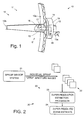
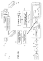
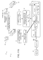
- Fig. 1 corresponds to Fig. 1 of U.S. Patent No. 5,243,351, and provides an example of a spinning aperture imaging radiometer system 10 in accordance with and modified by the principles of the present invention.
- the contents of U.S. Patent No. 5,243,351 are incorporated herein by reference.
- the spinning aperture imaging radiometer system 10 is adapted to synthesize super-resolved scene estimates, while removing line of sight jitter, and provide improved high resolution images when compared to conventional optical systems of the same weight, and when compared to a SpinAp system of the same weight.
- the spinning aperture imaging radiometer system 10 comprises a rotating strip aperture telescope 11 that includes primary 12a and secondary reflectors 12b.
- a tertiary reflector (not shown) may be employed in the telescope 11 under certain circumstances.
- the system 10 is shown in the form of a satellite comprising a stationary section 13 having an earth pointing antenna 13a.
- the telescope 11 is disposed on a platform 14, to which the stationary section 13 is also coupled.
- the spinning aperture imaging radiometer system 10 is adapted to record a number of image frames of a target scene imaged by the telescope 11 as the primary mirror 12a (comprising a strip aperture 12) rotates around the optical axis of the telescope 11.
- a line of sight stabilization mirror 15 and an image derotation device 16 are disposed along the optical path of the telescope 11 that are adapted to stabilize and derotate the image prior to its sensing by a detector array 17.
- the derotation device 16 counter rotates the image during the integration time of detectors comprising the detector array 17, under control of a rotation compensation controller 19. thereby providing a stationary image.
- the line of sight stabilization mirror 15 is used by a line of sight control system (such as may be provided by a signal processor or other dedicated control system) to remove high bandwidth line of sight errors, as well as line of sight errors due to orbital dynamics of the system 10.
- the target scene is imaged onto the detector array 17 located at the focal plane of the telescope 11 that is coupled to the signal processor 20 that is adapted to process the image frames.
- the signal processor 20 may comprise dedicated ground processor.
- the telescope 11, detector array 17 and related hardware are referred to herein as a sensor system 21. Individual image frames produced by the sensor system 21 are processed and combined in the signal processor 20 to synthesize super-resolved scene estimates in accordance with systems 10 and methods 30 of the present invention, and that are more specifically illustrated with reference to Figs. 2-11.
- Figs. 2-11 illustrate various embodiments of the SuperSpinAp processing methods 30 in accordance with the principles of the present invention employed by the spinning aperture radiometer system and methods associated with Fig. 1 appropriately modified to implement the principles of the present invention.
- a particular embodiment is selected based upon the observational scenario and timelines, the amount of available prior knowledge, and the available computational throughput of the processing chain.
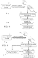
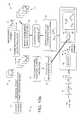
- Fig. 2 illustrates a first embodiment of a system 10 and method 30 in accordance with the present invention, comprising a top level SuperSpinAp image synthesis method 30 implemented in the signal processor 20.
- the SpinAp sensor 21 acquires and generates a set of strip aperture images 22 that are transferred to the SuperSpinAp processor 23.
- the SuperSpinAp processor 23 synthesizes a super-resolved scene estimate 24.
- the SpinAp sensor 21 acquires and generates a set of strip aperture images 22, which are transferred to the frame registration error processor 25.
- the frame registration error processor 25 determines the residual registration errors between the individual frames of the set.
- frame registration may be accomplished as follows. As the spinning strip aperture rotates around the optical axis of the telescope 11, the following occurs.
- the derotation device 16 counter-rotates during integration time of the detector array 17 to provide a temporally stationary image. An image frame is recorded and saved. If a rotating (relative to the scene) detector array architecture has been selected, the acquired frame is coordinate transformed and interpolated to a reference grid of the (not super-resolved) synthesized image.
- the data is Fourier transformed and stored. A new frame is recorded and saved. An estimate of the frame-to-frame misregistration of the recorded data due to random line of sight errors is obtained.
- the strip aperture images, or the Fourier transforms, are corrected for their line of sight errors and are stored. The preceding steps are sequentially repeated for each strip aperture image frame, or the frames are sequentially acquired and stored, and then global estimates of the line of sight are determined to register the frames.
- the registration processor 25 transfers the set of corrected frames, the set of uncorrected frames and registration error estimates between the frames, or both to the super-resolution processor 23. Using the corrected frames, or the uncorrected frames and the corresponding set of registration errors, the super-resolution estimation processor 23 generates the super-resolved scene estimate 24.
- the SpinAp sensor 21 acquires and generates a set of strip aperture images 22, which are transferred to the frame registration error processor 25.
- the frame registration error processor 25 determines the residual registration errors between the individual frames of the set.
- the registration processor 25 transfers the set of corrected frames, the set of uncorrected frames and registration error estimates between the frames, or both, to a SpinAp bandlimited image synthesis processor 26 and the super-resolution estimation processor 23.
- the SpinAp bandlimited image synthesis processor 26 generates images representative of full circular aperture images by means of the SpinAp process described in U.S. Patent No. 5,243,351.
- the super-resolution estimation processor uses the corrected frames, the set of uncorrected frames and registration error estimates between the frames, or both, as well as the SpinAp bandlimited image, the super-resolution estimation processor generates an estimate of the super-resolved scene 24.
- the SpinAp sensor 21 acquires and generates a set of strip aperture images 22, which are transferred to the frame registration error processor 25.
- the frame registration error processor 25 determines the residual registration errors between the individual frames of the set.
- the registration processor transfers the set of corrected frames, the set of uncorrected frames and registration error estimates between the frames, or both to the super-resolution processor 23.
- the correctly registered frames, or the set of uncorrected frames and the registration error estimates between the frames are transferred to the SpinAp bandlimited image synthesis processor 26.
- the SpinAp bandlimited image synthesis processor 26 generates images representative of full circular aperture images by means described in U.S. Patent No.
- the super-resolution estimation processor uses the corrected frames, or the uncorrected frames and the corresponding set of registration errors, as well as the SpinAp bandlimited image, the super-resolution estimation processor generates the super-resolved scene estimate 24, while incorporating a priori knowledge of the scene or object structure stored in data base 27.
- the SpinAp sensor 21 acquires and generates a set of strip aperture images 22, which are transferred to the frame registration error processor 25.
- the frame registration error processor 25 determines the residual registration errors between the individual frames of the set.
- the registration processor transfers the set of corrected frames, the set of uncorrected frames and registration error estimates between the frames, or both to the super-resolution processor 23.
- the correctly registered frames, or the set of uncorrected frames and the registration error estimates between the frames are transferred to the SpinAp bandlimited image synthesis processor 26.
- the SpinAp bandlimited image synthesis processor 26 generates images representative of full circular aperture images by means described by U.S. Patent No.
- the bandlimited SpinAp image is transferred to a training algorithm processor 28. Based upon information obtained from the SpinAp bandlimited image, the training processor extracts scene content and structure information, which is used to modify the a priori information contained in the data base 27. Using the corrected frames, or the uncorrected frames and the corresponding set of registration errors, as well as the SpinAp bandlimited image, the super-resolution estimation processor 23 generates the super-resolved scene estimate 24, while incorporating the a priori knowledge of the scene or object structure stored in data base 27, and modified by the training algorithm processor 28.
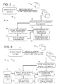
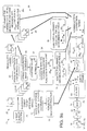
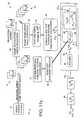
- Figs. 7a and 7b depict an embodiment of the SpinAp super-resolution processing method 23 used in the systems 10 and methods 30 of Figs. 2-6.
- the SpinAp sensor 21 acquires and generates a set of strip aperture images 22, which are transferred to the frame registration error processor 25.
- the frame registration error processor 25 determines the residual registration errors between the individual frames of the set.
- the registration processor transfers the set of corrected frames 29 and registration error estimates between the frames to the super-resolution processor 23.
- the correctly registered frames and the error estimates between the frames are transferred to the SpinAp bandlimited image synthesis processor 26.
- the SpinAp bandlimited image synthesis processor 26 generates images representative of full circular aperture images by means described by the U.S. Patent No. 5,243,351.
- the bandlimited SpinAp image is modified to provide a first estimate 33 of the super-resolved scene.
- the current super-resolved scene estimate 33 and the a priori information of the system response function 37 are used to determine the measurements for each frame that would result from observation of a current scene estimate 34.
- the determination of the anticipated measurements 34 is accomplished by convolving the current super-resolved scene estimate 33 with the system response function of the individual frames 37.
- the next steps 39 and 40 in the processing chain correspond to dividing the measurements 22, and the anticipated measurements 34 and subtracting unity, which is then convolved 40 with each frame's reflected response function 38.
- the resulting convolution 40 is summed for each frame 41 and then multiplied 42 by a scaling factor 43.
- the last steps in the first super-resolved estimates are to exponentiate 44 the output of steps 39 through 43 and multiply 45 the exponentiated result by the current super-resolved scene estimate 34.
- the result of steps 21 through 45 is the first true estimate 46 of the SpinAp super-resolved scene.
- the first true estimate 46 of the SpinAp super-resolved scene is then used as the current scene estimate 33, and the process continues for the desired number of iterations.
- Figs. 8a and 8b depict another embodiment of the SpinAp super-resolution processing method 23 used in the systems 10 and methods 30 of Figs. 2-6.
- the SpinAp sensor 21 acquires and generates a set of strip aperture images 22, which are transferred to the frame registration error processor 25.
- the frame registration error processor 25 determines the residual registration errors between the individual frames of the set.
- the registration processor transfers the set of corrected frames 29 and registration error estimates between the frames to the super-resolution processor 23.
- the correctly registered frames and the error estimates between the frames are transferred to the SpinAp bandlimited image synthesis processor 26.
- the SpinAp bandlimited image synthesis processor 26 generates images representative of full circular aperture images by means described by U.S. Patent No. 5.243,351.
- the bandlimited SpinAp image is modified to provide the first estimate 33 of the super-resolved scene sample mean.
- the current super-resolved scene sample mean estimate 33 and the a priori information of the system response function 37 are used to determine the measurements for each frame that would result from observation of the current scene sample mean estimate 34.
- the determination of the anticipated measurements 34 is accomplished by convolving the current super-resolved scene sample mean estimate 33 with the system response function of the individual frames 37.
- the next steps 39 and 40 in the processing chain correspond to dividing the measurements 22, and the anticipated measurements 34 and subtracting unity, which is then convolved 40 with each frame's reflected response function 38.
- the resulting convolution 40 is summed for each frame 41 and then multiplied 42 by a scaling factor 43.
- the last steps in the first super-resolved estimates are to exponentiate 44 the output of steps 39 through 43 and multiply 45 the exponentiated result by the current super-resolved scene sample mean estimate 33.
- the result of steps 21 through 46 is the first true estimate 46 of the SpinAp super-resolved scene.
- the first true estimate 46 of the SpinAp super-resolved scene is then used to update the current scene sample mean estimate 33, and the process continues for the desired number of iterations.
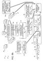
- Figs. 9a and 9b depicts another embodiment of the SpinAp super-resolution processing method 23 used in the systems 10 and methods 30 of Figs. 2-6.
- the SpinAp sensor 21 acquires and generates a set of strip aperture images 22 that are transferred to the frame registration error processor 25.
- the frame registration error processor 25 determines the residual registration errors between the individual frames of the set.
- the registration processor 25 transfers the set of corrected frames 29 and registration error estimates between the frames to the super-resolution processor 23. From the registered frames 29, the SuperSpinAp processor determines 29a the summed total of all detector and frame measurements, and the summed total of all detector measurements over all frame measurements less one. The sums are components of normalized correction terms 39a.
- the correctly registered frames and the error estimates between the frames are transferred to the SpinAp bandlimited image synthesis processor 26.
- the SpinAp bandlimited image synthesis processor 26 generates images representative of full circular aperture images by means described by U.S. Patent No. 5,243,351.
- the bandlimited SpinAp image is modified to provide the first estimate 33 of the super-resolved scene.
- the current super-resolved scene estimate 33 and the a priori information of the system response function 37 are used to determine the measurements for each frame that would result from observation of the current scene estimate 34.
- the determination of the anticipated measurements 34 is accomplished by convolving the current super-resolved scene estimate 33 with the system response function of the individual frames 37.
- the anticipated measurements 34 are also used to determine the summed total 35 of all frames and pixels that would result from the observation of the current scene estimate 33.
- the anticipated measurements 34 are summed over all pixels over all frames less one and all pixels 36 to produce a component of the normalized correction terms 39a.
- the next step 40 in the processing chain corresponds to dividing the measurements 22 and the anticipated measurements 34, which is then convolved with each frame's reflected response function 38.
- the resulting convolution 40 is summed for each frame 41, then normalization correction terms comprising results from steps 29a, 35 and 36 are subtracted from this sum. This result is multiplied 42 by a scaling factor 43.
- the last steps in the first super-resolved estimates are to exponentiate 44 the output of steps 39 through 43 and multiply 45 the exponentiated result by the current super-resolved scene estimate 33.
- the result of steps 21 through 45 is the first true estimate 46 of the SpinAp super-resolved scene.
- the first estimate of the SpinAp super-resolved scene 46 is then used as the current scene estimate 33, and the process continues for the desired number of iterations.
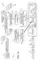
- Figs. 10a and 10b shows another embodiment of the SpinAp super-resolution processing method 23 used in the systems 10 and methods 30 of Figs. 2-6.
- the SpinAp sensor 21 acquires and generates a set of strip aperture images 22 that are transferred to the frame registration error processor 25.
- the frame registration error processor 25 determines the residual registration errors between the individual frames of the set.
- the frame registration error processor 25 transfers the set of corrected frames 29 and registration error estimates between the frames to the super-resolution processor 23.
- the correctly registered frames and the error estimates between the frames are transferred to the SpinAp bandlimited image synthesis processor 26.
- the SpinAp bandlimited image synthesis processor 26 generates images representative of full circular aperture images by means described by U.S. Patent, No. 5,243,351.
- the bandlimited SpinAp image is modified to provide the first estimate 33 of the super-resolved scene ensemble mean.
- the current super-resolved scene ensemble mean estimate 33 and the a priori information of the system response function 37 are used to determine the measurements for each frame that would result from observation of the current scene ensemble mean estimate 34.
- the determination of the anticipated measurements 34 is accomplished by convolving the current super-resolved scene ensemble mean estimate 33 with the system response function of the individual frames 37.
- the next steps 39 and 40 in the processing chain correspond to dividing the measurements 22 and the anticipated measurements 34, which is then convolved 40 with the reflected response function 38 of each frame.
- the resulting convolution 40 is summed for each frame 41 and then multiplied 42 by a scaling factor 43.
- the last step in the first super-resolved estimate is to multiply 45 the output of steps 39 through 43 by the current super-resolved scene ensemble mean estimate 34.
- the result of steps 21 through 45 is the first true estimate 46 of the SpinAp super-resolved scene ensemble mean.
- the first estimate of the SpinAp super-resolved scene 46 is then used as the current scene ensemble mean estimate 33, and the process continues for the desired number of iterations.
- Figs. 11a and 11b depict another embodiment of the SpinAp super-resolution processing method 23 used in the systems 10 and methods 30 of Figs. 2-6.
- the SpinAp sensor 21 acquires and generates a set of strip aperture images 22, which are transferred to the frame registration error processor 25.
- the frame registration error processor 25 determines the residual registration errors between the individual frames of the set.
- the registration processor transfers the set of corrected frames 29 and registration error estimates between the frames to the super-resolution processor 23.
- the correctly registered frames and the error estimates between the frames are transferred to the SpinAp bandlimited image synthesis processor 26.
- the SpinAp bandlimited image synthesis processor 26 generates images representative of full circular aperture images by means described by U.S. Patent No. 5,243,351.
- the bandlimited SpinAp image is modified to provide the first estimate 33 of the super-resolved scene ensemble mean.
- the current super-resolved scene ensemble mean estimate 33 and the a priori information of the system response function 37 associated with the first SpinAp frame measurement are used to determine the measurement for the first frame that would result from observation of the current scene ensemble mean estimate 34.
- the determination of the anticipated measurement 34 is accomplished by convolving the current super-resolved scene ensemble mean estimate 33 with the system response function of the first frame 37.
- the next steps 39 and 40 in the processing chain correspond to dividing the first SpinAp measurement 22 and the anticipated first measurement 34, which is then convolved 40 with the first frame's reflected response function 38.
- Unity is subtracted 39b from the resulting convolution and the result is multiplied 41a by the current estimate 34 of the scene ensemble mean. This result is multiplied 42 by a scaling factor 43.
- the last step in the first super-resolved estimate is to add 44a the output of steps 39 through 43 to the current super-resolved scene ensemble mean estimate 34.
- the result of steps 21 through 45 is the first true estimate 46 of the SpinAp super-resolved scene ensemble mean.
- the first estimate 46 of the SpinAp super-resolved scene is then used as the current scene ensemble mean estimate 33, and the process continues for the desired number of iterations.
- the discrete form of the convolution of the scene with the system response function can be represented as, where j indicates the detector output from location r j, and the k indicates the discrete scene element geometrically projected to the focal plane spatial position r k.
- G m can be represented by a column matrix, denoted by G m , with elements corresponding to each of the detector measurements in the focal plane array.
- H m can be represented by a two dimensional matrix, denoted by H m , with elements corresponding to the system response function of the electro-optical sensor.
- the scene may be represented as a column matrix, denoted by S m , with elements S k corresponding to samples of the m th scene realization projected to the super-resolution grid.
- One embodiment of the SuperSpinAp processing procedure uses a Bayes estimation approach commonly referred to as maximum a posteriori probability estimation.
- Maximum a posteriori estimation seeks a value of the unknown object that maximizes the conditional probability of the object given the measurement.
- a maximum a posteriori approach to SuperSpinAp seeks an estimate of the super-resolved scene that maximizes the probability of the super-resolved scene given the entire set of SpinAp sensor measurements.
- the imaging model given in equation 2 is specialized to in which the scene, S, is assumed to be a single scene realization during the SpinAp measurement interval.
- G is the total measurement matrix, which is a block column matrix consisting of individual frame measurement matrices, given by where n f is the total number of frames acquired.
- S is the matrix of scene samples projected to the super-resolution grid.
- the probability density for the one dimensional scene matrix can be expressed as the product of probability density functions associated with each element, i.e.,
- the probability density function of the scene pixel element is postulated to be the Poisson distribution where k is an index designating the projected pixel element of the scene.
- the joint probability density of the total measurement vector given the scene can be expressed as the product of individual mth frame joint probability densities.
- conditional probability of the occurrence of the frame measurement given the scene can be expressed as a product of the individual pixel probability densities conditioned on the scene.
- the total measurement conditional probability density is therefore given by the product of pixel and frame measurement probabilities conditioned on the scene,
- the individual measurement conditional probabilities can be expressed as, where ⁇ k H m (j-k)S(k) is the mean value of the individual detector measurement.
- the probability of the measurement matrix G given S can be expressed as ln[p(G
- S)] ⁇ j ⁇ m ln[p(G m (j)
- Picard's method An iterative procedure, known as Picard's method, may be used to solve for the most probable unknown scene solution of the nonlinear equations.
- the iterative procedure is described by the equation where superscripts [n] and [n+1] refer to current and next scene estimates, respectively.
- the iterative process includes remappings between the super-resolution coordinate grid and the measurement (or an intermediate reference) grid.
- One embodiment of the iterative algorithm accommodates for the differences in sample spacing between the measurement coordinate grids and the super-resolved coordinate grids by performing downsampling of the super-resolution grid by block averaging, and upsampling of the measurement grid by replication. Alternately, the upsampling and downsampling can be implemented using a higher-order interpolation technique.
- the previously described SuperSpinAp embodiment uses a maximum a posteriori estimation approach to estimate the scene S.
- G is defined as in equation 6, and S is analogously defined for the scene realizations.
- the probability density for the one dimensional scene matrix can be expressed as the product of probability density functions associated with each element, i.e.,
- the probability density function of the scene pixel element is postulated to be the Poisson distribution where k is an index designating the scene's projected pixel element.
- the ensemble mean S(k) is approximated by the sample mean equation 3a, yielding where a dummy index p is used to distinguish counting over frames from a specific frame m.
- the joint probability density of the total measurement vector given the scene can be expressed as the product of individual mth frame joint probability densities
- conditional probability of the occurrence of the frame measurement given the scene can be expressed as a product of the individual pixel probability densities conditioned on the scene.
- the total measurement conditional probability density is therefore given by the product of pixel and frame measurement probabilities conditioned on the scene.
- the individual measurement conditional probabilities can be expressed as, where G(j) is the ensemble mean value of the individual detector measurement.
- the ensemble mean is estimated by the sample mean ⁇ G m (j)> in equation 3, yielding the measurement probability density
- the probability of the measurement matrix G given S can be expressed as ln[p(G
- S)] ⁇ j ⁇ m ln[p(G m (j)
- Picard's method An iterative procedure, known as Picard's method, can be used to solve for the most probable unknown scene solution of the nonlinear equations.
- the iterative procedure is described by the equation where the superscript [n] and [n+1] refer to the current and next scene estimates, respectively.
- upsampling denoted by ⁇
- down-sampling denoted by
- a maximum a posteriori approach using a single probability density accommodating the total measurements is described below.
- the algorithmic procedure just described essentially has two unknowns that must be determined, the super-resolved scene pixel and the super-resolved scene pixel's mean value.
- Implementing the algorithm associated with the first set of super-resolved scene estimation equations incorporated an ad hoc procedure to estimate the scene pixel's mean value.
- Implementing the algorithm associated with the second set of super-resolved scene estimation equations uses sample statistics to approximate the ensemble mean for each scene pixel.
- An alternative approach recognizes the total number of independent random variables to be a constant, i.e., the summed total of all measurements or the summed total of a fraction of the measurements is a random variable conditioned upon the individual measurements.
- the probability density functions for the individual scene and measurement elements are postulated to be Poisson, i.e. and where S(k ⁇ ) is the scene's k ⁇ th projected "pixel's" mean value, and G m (k ⁇ ) is the j th detectors measurement from frame m.
- equation (28) applies to the set of SuperSpinAp measurements depends upon selecting the measurement not explicitly present in the conditional probability. Since the numbering of the measurements is arbitrary, the conditional probability of the measurements given the summed total of measurements is expressed as p(G l (1),...,G M (1); G l (2),...,G M (2);... G l (N),...,G M (N)
- the ⁇ and ⁇ indicate the super-resolved and measurement coordinate spatial grids.
- Determining the maxima of the probability densities is equivalent to determining the maxima of ln[p(S
- the individual measurements are assumed to be statistically independent Poisson random variables, and the mean value of the individual measurements as well as the summed value of all or part of the total measurements summed are assumed to be Poisson random variables.
- the mean values of the Poisson random variables are assumed to be the noise free measurement, i.e. the mean value of the summed total SpinAp measurements is and the mean value of the individual detector measurements is
- the logarithm of the measurements conditioned on the scene is ln[p(S
- G_,G tot )] ln[p(G_,G tot
- the solution for the super-resolved scene must satisfy a set of nonlinear coupled equations generated by requiring the derivative of the conditional probability with respect to the scene super-resolved pixel to vanish.
- the set of simultaneous equations for the embodiment described in this section are:
- the numerical solution of the set of simultaneous equations can proceed by exponentiation and applying the iterative method of Picard.
- a summed measurement super-resolution embodiment will now be described.
- an additional set of super-resolution equations is established based on the total number of measured photons in the SpinAp frames.
- the super-resolved scene value is determined by requiring the estimated scene value to be an extrema of the conditional probability density for the scene value given the occurrence of the total measurements, as well as an extrema of the conditional probability density for the scene value given the measured SpinAp frames.
- the two sets of equations can then be used to eliminate the unknown mean pixel value, leaving a set of nonlinear equations for the super-resolved scene pixel value.
- the set of nonlinear equations may be solved using the method of Picard. Details of the procedures leading to the definition of this alternate super-resolution procedure are described below
- the discrete form of the m th frame's noise free image measurement, and the total of all detector noise free measurements for all of the frames will be expressed as
- j is a one dimensional index associated with the detector location vector r j
- k is a one dimensional index associated with the detector location vector r k .
- the modified maximum a posteriori approach uses two different Bayes probability rules to find an estimate of the super-resolved scene.
- G) p(G
- G tot ) p(G tot
- G is the total measurement matrix, which is a block column matrix consisting of individual frame measurement matrices, and S a column matrix consisting of individual scene elements projected to the super-resolution coordinate grid, or where n f is the total number of measurements frames, and n pixel is the total number of super-resolved points in the estimate of the super-resolved scene.
- the self consistent super-resolution approach incorporating the conditional probability for the total measurement given the scene seeks an estimate for the scene, S, that maximizes the conditional probability for the scene given the complete set of SpinAp measurements, and also maximizes the conditional probability for the scene given the sum of all SpinAp measurements, i.e. a solution for S is sought that simultaneously maximizes p(S
- S an estimate for the scene
- S that maximizes the conditional probability for the scene given the complete set of SpinAp measurements
- the self consistency requirement is incorporated by assuming the mean values of the individual detector measurements, and the mean value of the sum total of SpinAp measurements correspond to the noise free set of measurements, i.e.
- the ⁇ and ⁇ indicate the super-resolved and "measurement" coordinate spatial grids.
- the joint probability density of the total measurement vector given the scene can be expressed as the product of individual m th frame joint probability densities
- conditional probability of the occurrence of the frame measurement given the scene can be expressed as a product of the individual pixel probability densities conditioned on the scene.
- the total measurement conditional probability density is therefore given by the product of pixel and frame measurement probabilities conditioned on the scene,
- the probability density for the one dimensional scene matrix can be expressed as the product of probability density functions associated with each element, i.e.,
- the probability density function of the scene pixel element is postulated to be where S(k ⁇ ) is the scene's k ⁇ th projected "pixel's" mean value.
- G tot ) depends upon determining the logarithm of the conditional probability of the summed total measurement given the scene,
- the Stirling approximation ln[x!] ⁇ xln[x] - x may be used to simplify the calculation procedure.
- the Stirling approximation applied to the two conditional probabilities of interest yields
- the two sets of equations (35) and (36) can be solved simultaneously to formulate an estimation procedure for S(l ⁇ ) or S(l ⁇ ) .
- the SuperSpinAp embodiments in described above apply the maximum a posteriori estimation technique.
- An alternate approach to SuperSpinAp processing uses a Bayes estimation approach commonly refereed to as maximum likelihood estimation.
- Maximum likelihood estimation seeks a value of the unknown object that maximizes the conditional probability of the measurements given the object. That is, the maximum likelihood estimate of the object is the object that most likely led to the entire set of observed SpinAp sensor measurements.
- G is the total measurement matrix, which is a block column matrix consisting of individual frame measurement matrices, given by where n f is the total number of frames acquired.
- S is a block column matrix associated with n f realizations of the random scene
- the maximum likelihood estimate is the value of the scene mean, S , which maximizes the likelihood function P(G
- the joint probability density of the total measurement vector given the scene can be expressed as the product of individual m th frame joint probability densities
- conditional probability of the occurrence of the frame measurement given the scene can be expressed as a product of the individual pixel probability densities conditioned on the scene
- the total measurement conditional probability density is therefore given by the product of pixel and frame measurement probabilities conditioned on the scene,
- the individual measurement conditional probabilities can be expressed as, where is the mean value of the individual detector measurement.
- Equation (43) Substituting Equation (43) into Equation (42) yields
- Equation (44) each side of Equation (44) is multiplied by S (l) and the estimate is formed iteratively as where the superscript n indicates the iteration number.
- This method of computing the SuperSpinAp maximum likelihood estimate is an expectation maximization algorithm.
- Expectation maximization algorithms converge to a maximum likelihood estimate of the scene mean.
- a multiplicative correction factor is computed from the entire set of n f SpinAp measurements.
- a recursive expectation maximization algorithm may be used to compute the maximum likelihood estimate.
- a recursive algorithm updates the estimate based on each frame individually, thereby reducing the computational requirements for determining the maximum likelihood estimation.
- the recursive form of the expectation maximization algorithm extends the method developed by Titterington in Journal of the Royal Statistical Society - B, Vol. 46, No. 2, pages 257-267, 1984) to apply to the SuperSpinAp.
- This recursive expectation maximization algorithm may be initialized using the methods described previously, or be initializing each element of the scene mean estimate to a constant value based on the average number of photons in the SpinAp frames
- the SuperSpinAp embodiments described above comprise two broad solution approaches for estimating the unknown scene - maximum a posteriori estimation, and maximum likelihood estimation.
- four embodiments are disclosed including a maximum a posteriori approach in which the scene mean S (l) is estimated in an ad hoc manner, by estimating the scene mean as equal to the current estimate of the scene, a maximum a posteriori approach in which the scene mean S (l) is estimated using sample statistics, resulting in a recursive algorithm for estimating each realization of the scene S q (l), followed by a re-estimation of the sample mean, a maximum a posteriori approach in which a single probability density function is formulated on the measurements and the total photons in the set of measured SpinAp frames, and a maximum a posteriori approach in which a separate probability density function is formulated on the total photons in the set of measured SpinAp frames, followed by simultaneous solution of two sets of nonlinear equations.
- the first embodiment uses the set of measured SpinAp frames to form an estimate of the scene ensemble mean S (l) in which the entire set of SpinAp frames is used in each update of the estimate.
- a recursive algorithm is used, in which the scene ensemble mean estimate is updated using one SpinAp frame measurement at a time.
- Each of the maximum likelihood embodiments are expectation maximization procedures, thereby guaranteeing that the Picard iterations converge to a maximum likelihood estimate.
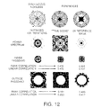
- Fig. 12 depicts results of a demonstration of the SuperSpinAp synthesis method 30 use to generate a super-resolved image of a radial test pattern.
- Fig. 13 depicts an example of SuperSpinAp synthesis performance. Quantitative measures of the performance are obtained by determining correlation coefficients between the known reference power spectrum of an object and the power spectrum of the super-resolved image.
- Fig. 14 depicts an example of SuperSpinAp synthesis performance where the true scene is a horizontal bar target. Quantitative measures of the performance are found by determining correlation coefficients between the known reference power spectrum of an object and the power spectrum of the super-resolved image.
- One embodiment of the imaging system 10 comprises a rotating strip aperture wide field of view telescope 11, a two-dimensional detector array 17 for detecting images in the focal plane of the telescope, rotation compensation apparatus 16, 19 for preventing rotational smear during the integration time of the detectors, a signal processor 20 for recording a plurality of image frames 22 of a scene that is imaged by the telescope 11 as it rotates around its optical axis, and an estimation processor 23 employing the present method 30 for synthesizing the super-resolved scene estimate 24 from the recorded images.
- the super-resolved image synthesis method 30 uses a plurality of rotating strip aperture measurements within the strip aperture passband and within the passband of an equivalent bandlimited synthesized full circular aperture to estimate the spatial frequency information outside the total measurement passband, and/or outside the passband of the equivalent bandlimited synthesized full circular aperture, as well as within the equivalent bandlimited passband.
- Knowledge of the spatial response function of the strip aperture, the spatial response function of the detector array 17, noise statistics, and the temporal registration of each of the recorded strip aperture images permits synthesis of the super-resolved full aperture image by the sensor system 10 and image synthesis method 30.
- the super-resolved image synthesis method 30 may be employed in the spatial domain, the spatial frequency domain, or both.
Landscapes
- Physics & Mathematics (AREA)
- Electromagnetism (AREA)
- General Physics & Mathematics (AREA)
- Engineering & Computer Science (AREA)
- Multimedia (AREA)
- Radar, Positioning & Navigation (AREA)
- Remote Sensing (AREA)
- Image Processing (AREA)
- Photometry And Measurement Of Optical Pulse Characteristics (AREA)
- Image Analysis (AREA)
Claims (10)
- Système de capteur radiométrique à ouverture en bande tournant (10) comprenant :caractérisé par un processeur d'estimation (23) pour synthétiser des estimations (24) de la scène d'image observée, à partir des images enregistrées pour des fréquences spatiales plus élevées que la fréquence spatiale de coupure de l'ouverture en bande tournante (12).un télescope (11) constitué par une ouverture en bande tournante (12) ayant une fréquence spatiale de coupure prédéterminée, ce télescope (11) tournant autour d'un axe optique pour produire des images d'une scène en séquence temporelle;un réseau de détecteurs bidimensionnel (17) disposé dans un plan focal du télescope pour générer un ensemble d'images d'ouverture en bande (22); etun processeur de signal (20) couplé au réseau de détecteurs (17) pour enregistrer une pluralité d'images de la scène d'image comprenant l'ensemble d'images d'ouverture en bande (22), au fur et à mesure que l'ouverture en bande tournante (12) tourne autour de l'axe optique du télescope (11),
- Système (10) selon la revendication 1, caractérisé en ce que le processeur de signal (20) est en outre caractérisé par un processeur d'erreurs de coïncidence d'images (25) couplé au processeur d'estimation (23) pour déterminer les erreurs de coïncidence résiduelles entre des images individuelles de l'ensemble d'images d'ouverture en bande (22).
- Système (10) selon la revendication 1 ou 2, caractérisé en ce que le processeur de signal (20) est en outre caractérisé par un processeur de synthèse d'images à bande limitée (26), couplé entre le processeur d'erreurs de coïncidence d'images (25) et le processeur d'estimation (23), pour générer des images représentatives d'une ouverture circulaire complète.
- Système selon l'une quelconque des revendications 1 - 3, caractérisé en ce que le processeur de signal (20) est en outre caractérisé par :une base de données de synthèse d'images (27) pour stocker une connaissance a priori correspondant à la scène; etun processeur d'algorithme d'apprentissage (28) couplé entre le processeur de synthèse d'images à bande limitée (26) et la base de données de synthèse d'images (27), pour extraire des images (22) une information de contenu et de structure de scène, et pour modifier l'information a priori contenue dans la base de données (27), cette information étant traitée par le processeur de signal (20) pour générer une estimation (24) de la scène à super-résolution (22).
- Système (10) selon l'une quelconque des revendications 1 - 4, caractérisé en ce que le processeur d'estimation (23) synthétise des estimations de la scène observée en utilisant une procédure d'estimation à vraisemblance maximale qui utilise un ensemble d'images mesurées pour former une estimation de la moyenne d'ensemble de la scène, dans laquelle l'ensemble complet d'images est utilisé dans chaque actualisation de l'estimation.
- Procédé de synthèse d'image pour l'utilisation dans un système imageur comprenant un télescope à ouverture en bande tournant (11) qui tourne autour d'un axe optique, un réseau de détecteurs bidimensionnel (17) disposé dans un plan focal du télescope (11) pour détecter des images et générer (21) un ensemble d'images d'ouverture en bande (22), des moyens de compensation de rotation (16) pour produire une image fixe pendant le temps d'intégration de détecteurs du réseau de détecteurs (17), et un processeur de signal (20) pour enregistrer une pluralité d'images d'une scène dont l'image est formée par le télescope (11) pendant qu'il tourne autour de l'axe optique du télescope (11), et pour synthétiser une image d'ouverture circulaire complète à partir des images enregistrées, dans lequel le procédé de synthèse d'image est caractérisé par l'étape suivante :on synthétise (23) un spectre d'image d'ouverture complète à super-résolution, en formant un produit (45) d'une estimation présente de la scène à super-résolution et d'une fonction non linéaire (44) de l'estimation présente.
- Procédé de synthèse d'image (30) selon la revendication 6, caractérisé en ce que la fonction non linéaire (44) de l'estimation présente est un produit d'exponentielles de la pluralité (41) de mesures de rotation multipliées (43) par le nombre d'images qui sont mesurées, et dans lequel les arguments des exponentielles (44) sont une fonction des mesures (29), une fonction de réponse (RHm(r)) du système imageur, et l'estimation présente (33) de la scène à super-résolution.
- Procédé de synthèse d'image (30) selon la revendication 7, caractérisé en ce que l'argument des exponentielles (44) associé à chaque position de rotation est obtenu en effectuant une convolution (40) de la fonction de réponse (RHm(r)) de l'ouverture en bande réfléchie pour la position de rotation particulière, avec une fonction auxiliaire (39) qui est déterminée en divisant des mesures de pixels d'image (Gm(l)) par un facteur (34) consistant en une convolution de l'estimation présente de la scène à super-résolution avec la fonction de réponse spatiale de l'ouverture en bande pour la position de rotation particulière.
- Procédé de synthèse d'image (30) selon la revendication 8, caractérisé en outre par l'étape de détermination (25) d'erreurs de coïncidence résiduelles entre des images individuelles de l'ensemble, par les opérations suivantes :on enregistre et on stocke une image;on effectue une interpolation et une transformation de coordonnées de l'image stockée de façon qu'elle corresponde à une grille de coordonnées de référence de l'image synthétisée;on enregistre et on stocke le reste des images;on estime image par image l'erreur de coïncidence des images qui est due à des erreurs aléatoires de ligne de visée;on corrige, en ce qui concerne les erreurs de ligne de visée, l'une sélectionnée des images d'ouverture en bande, et on stocke l'image corrigée;on répète séquentiellement les étapes précédentes pour chaque image d'ouverture en bande;
et après que toutes les images ont été traitées et sauvegardées; eton fait coïncider chacune des images d'ouverture en bande individuelles. - Procédé de synthèse d'image (30) selon la revendication 8 ou 9, caractérisé en outre par l'étape de génération (26) d'images représentatives d'images à bande limitée d'une ouverture circulaire complète, en utilisant l'ensemble d'images corrigées, l'ensemble d'images non corrigées et des estimations d'erreurs de coïncidence entre les images;
et dans lequel l'étape de synthèse (23) du spectre d'image d'ouverture complète à super-résolution utilise les images corrigées, l'ensemble d'images non corrigées et les estimations d'erreurs de coïncidence entre les images, et les images à bande limitée, pour générer l'estimation de la scène à super-résolution (24).
Applications Claiming Priority (2)
| Application Number | Priority Date | Filing Date | Title |
|---|---|---|---|
| US635073 | 1990-12-28 | ||
| US08/635,073 US6155704A (en) | 1996-04-19 | 1996-04-19 | Super-resolved full aperture scene synthesis using rotating strip aperture image measurements |
Publications (3)
| Publication Number | Publication Date |
|---|---|
| EP0802425A2 EP0802425A2 (fr) | 1997-10-22 |
| EP0802425A3 EP0802425A3 (fr) | 1997-12-29 |
| EP0802425B1 true EP0802425B1 (fr) | 1999-11-03 |
Family
ID=24546332
Family Applications (1)
| Application Number | Title | Priority Date | Filing Date |
|---|---|---|---|
| EP97106509A Expired - Lifetime EP0802425B1 (fr) | 1996-04-19 | 1997-04-19 | Synthèse d'image à ouverture totale au moyen de mesures d'images à ouverture tournante en forme de bandes |
Country Status (4)
| Country | Link |
|---|---|
| US (1) | US6155704A (fr) |
| EP (1) | EP0802425B1 (fr) |
| JP (1) | JPH1063821A (fr) |
| DE (1) | DE69700718T2 (fr) |
Cited By (1)
| Publication number | Priority date | Publication date | Assignee | Title |
|---|---|---|---|---|
| CN108896991A (zh) * | 2018-04-26 | 2018-11-27 | 西安空间无线电技术研究所 | 一种基于数据融合的星载分布式综合孔径微波辐射计系统 |
Families Citing this family (15)
| Publication number | Priority date | Publication date | Assignee | Title |
|---|---|---|---|---|
| US6466894B2 (en) * | 1998-06-18 | 2002-10-15 | Nec Corporation | Device, method, and medium for predicting a probability of an occurrence of a data |
| WO2002103580A2 (fr) * | 2001-06-15 | 2002-12-27 | Massachusetts Institute Of Technology | Estimation adaptative de moyennes et normalisation de donnees |
| US7123780B2 (en) * | 2001-12-11 | 2006-10-17 | Sony Corporation | Resolution enhancement for images stored in a database |
| US6603424B1 (en) * | 2002-07-31 | 2003-08-05 | The Boeing Company | System, method and computer program product for reducing errors in synthetic aperture radar signals |
| ES2392512T3 (es) * | 2004-01-27 | 2012-12-11 | Saab Ab | Método para la reducción del desenfoque angular en imágenes de radar |
| US7064702B1 (en) | 2005-03-01 | 2006-06-20 | The Boeing Company | System, method and computer program product for reducing quadratic phase errors in synthetic aperture radar signals |
| JP4814840B2 (ja) * | 2007-05-23 | 2011-11-16 | オリンパス株式会社 | 画像処理装置又は画像処理プログラム |
| CN101261319B (zh) * | 2008-04-18 | 2010-12-01 | 华中科技大学 | 一种综合孔径辐射计成像校正方法 |
| JP2012061141A (ja) * | 2010-09-16 | 2012-03-29 | Canon Inc | 被検体情報取得装置及び被検体情報取得方法 |
| US8362947B2 (en) * | 2011-03-29 | 2013-01-29 | Victor Gorelik | Method for obtaining object-plane field from its two images |
| US20140027577A1 (en) * | 2012-07-26 | 2014-01-30 | Alliant Techsystems Inc. | Imaging satellite system and method |
| US10154193B1 (en) | 2016-03-08 | 2018-12-11 | National Technology & Engineering Solutions Of Sandia, Llc | Noncircular aperture imaging system |
| CN108512608B (zh) * | 2018-04-09 | 2023-11-28 | 中国科学技术大学 | 一种基于多孔径合成的量子通信接收装置 |
| DE102020107965B3 (de) * | 2020-03-23 | 2021-09-09 | Fraunhofer-Gesellschaft zur Förderung der angewandten Forschung eingetragener Verein | Verfahren zur optischen Bestimmung einer Intensitätsverteilung |
| CN119179066B (zh) * | 2024-11-25 | 2025-02-07 | 中国人民解放军国防科技大学 | 多孔径成像系统协同定位点标校方法及装置 |
Family Cites Families (17)
| Publication number | Priority date | Publication date | Assignee | Title |
|---|---|---|---|---|
| EP0181935B1 (fr) * | 1984-05-07 | 1989-07-12 | Hughes Aircraft Company | Radiometre a micro-ondes utilisant l'inversion de faisceaux en eventail |
| US4724439A (en) * | 1984-05-07 | 1988-02-09 | Hughes Aircraft Company | Microwave radiometer using fanbeam inversion |
| US5160934A (en) * | 1984-08-27 | 1992-11-03 | The United States Of America As Represented By The Secretary Of The Navy | Cross-switched MICRAD seeker |
| US4739332A (en) * | 1984-09-17 | 1988-04-19 | Hughes Aircraft Company | Fanbeam inversion radar |
| US4825215A (en) * | 1986-07-03 | 1989-04-25 | Hughes Aircraft Company | Radiometric imager having a frequency-dispersive linear array antenna |
| US4876602A (en) * | 1988-05-02 | 1989-10-24 | Hughes Aircraft Company | Electronic focus correction by signal convolution |
| DE3922428A1 (de) * | 1989-07-07 | 1991-01-17 | Deutsche Forsch Luft Raumfahrt | Verfahren zur extraktion von bewegungsfehlern eines ein kohaerentes abbildungsradarsystem mitfuehrenden traegers aus radar-rohdaten und einrichtung zur durchfuehrung des verfahrens |
| DE4007611C1 (fr) * | 1990-03-09 | 1991-05-16 | Deutsche Forschungsanstalt Fuer Luft- Und Raumfahrt Ev, 5300 Bonn, De | |
| US5161204A (en) * | 1990-06-04 | 1992-11-03 | Neuristics, Inc. | Apparatus for generating a feature matrix based on normalized out-class and in-class variation matrices |
| US5072226A (en) * | 1990-06-07 | 1991-12-10 | Hughes Aircraft Company | Radiometer system incorporating a cylindrical parabolic reflector and minimum redundancy array feed |
| US5122805A (en) * | 1991-02-06 | 1992-06-16 | Radian Corporation | Radio acoustic sounding system for remotely determining atmospheric temperature profiles |
| US5128530A (en) * | 1991-05-28 | 1992-07-07 | Hughes Aircraft Company | Piston error estimation method for segmented aperture optical systems while observing arbitrary unknown extended scenes |
| US5164730A (en) * | 1991-10-28 | 1992-11-17 | Hughes Aircraft Company | Method and apparatus for determining a cross-range scale factor in inverse synthetic aperture radar systems |
| US5122803A (en) * | 1991-11-06 | 1992-06-16 | The United States Of America As Represented By The Secretary Of The Army | Moving target imaging synthetic aperture radar |
| US5243351A (en) * | 1992-06-25 | 1993-09-07 | Hughes Aircraft Company | Full aperture image synthesis using rotating strip aperture image measurements |
| US5350911A (en) * | 1993-04-09 | 1994-09-27 | Hughes Aircraft Company | Wavefront error estimation derived from observation of arbitrary unknown extended scenes |
| EP0634669B1 (fr) * | 1993-07-15 | 1997-09-24 | Daimler-Benz Aerospace Aktiengesellschaft | Procédé de classification d'un objet et l'application du procédé |
-
1996
- 1996-04-19 US US08/635,073 patent/US6155704A/en not_active Expired - Lifetime
-
1997
- 1997-04-19 DE DE69700718T patent/DE69700718T2/de not_active Expired - Lifetime
- 1997-04-19 EP EP97106509A patent/EP0802425B1/fr not_active Expired - Lifetime
- 1997-04-21 JP JP9117621A patent/JPH1063821A/ja active Pending
Cited By (2)
| Publication number | Priority date | Publication date | Assignee | Title |
|---|---|---|---|---|
| CN108896991A (zh) * | 2018-04-26 | 2018-11-27 | 西安空间无线电技术研究所 | 一种基于数据融合的星载分布式综合孔径微波辐射计系统 |
| CN108896991B (zh) * | 2018-04-26 | 2021-04-13 | 西安空间无线电技术研究所 | 一种基于数据融合的星载分布式综合孔径微波辐射计系统 |
Also Published As
| Publication number | Publication date |
|---|---|
| EP0802425A3 (fr) | 1997-12-29 |
| JPH1063821A (ja) | 1998-03-06 |
| DE69700718T2 (de) | 2000-06-21 |
| EP0802425A2 (fr) | 1997-10-22 |
| DE69700718D1 (de) | 1999-12-09 |
| US6155704A (en) | 2000-12-05 |
Similar Documents
| Publication | Publication Date | Title |
|---|---|---|
| US5243351A (en) | Full aperture image synthesis using rotating strip aperture image measurements | |
| EP0802425B1 (fr) | Synthèse d'image à ouverture totale au moyen de mesures d'images à ouverture tournante en forme de bandes | |
| EP0802426B1 (fr) | Détection d'objets mobiles et d'événements transitoires au moyen de mesures d'images à ouverture tournante en forme de bandes | |
| US6987255B2 (en) | State space wavefront reconstructor for an adaptive optics control | |
| JP6570991B2 (ja) | 大口径望遠鏡における、非同一平面上の(anisoplanatic)画像形成のためのレンズレット、ビームウォーク(beamwalk)、及びチルトの多様化 | |
| JP3200372B2 (ja) | シーンクラッタを抑制するための最小スパン勾配フィルタを有する物体検出システム | |
| EP0977054A2 (fr) | Détermination de l'information d'altitude | |
| CN116299551B (zh) | 一种太赫兹sar二维自聚焦成像算法 | |
| US7113268B2 (en) | Scintillation tolerant optical field sensing system and associated method | |
| US20260011019A1 (en) | Initial orbit determination using angular velocity and angular acceleration measurements | |
| CN119533327B (zh) | 基于行星变焦的射电望远镜的离焦全息测量方法 | |
| Kim et al. | Fast Fourier-Domain Optimization Using Hybrid L 1−/L ${} _ {p} $-Norm for Autofocus in Airborne SAR Imaging | |
| US8351738B2 (en) | Method of estimating at least one deformation of the wave front of an optical system or of an object observed by the optical system and associated device | |
| Muruganandan et al. | Improving the resolution of low earth orbit objects by multi-exposure imaging and deconvolution | |
| JP7646094B2 (ja) | シーンのレーダ画像を生成するためのシステムおよび方法 | |
| Kim et al. | Map fusion method for superresolution of images with locally varying pixel quality | |
| US7372569B2 (en) | Method of correcting alignment errors in a segmented reflective surface | |
| Qiu et al. | Design and Verification of Super-Resolution Reconstruction Algorithm for Remote Sensing | |
| Sun et al. | Remote sensing stereo image pair spatial resolution improvement with iterative maximum a posteriori scheme based on PSF measurement | |
| Lin | Sub-pixel target detection and tracking | |
| Kundur et al. | Blind Image Deconvolution: An Algorithmic Approach to Practical Image Restoration1 | |
| Worden et al. | The AFGL Image Reconstruction Program II Speckle Interferometry. | |
| Ochsenbein et al. | Scale sensitive deconvolution |
Legal Events
| Date | Code | Title | Description |
|---|---|---|---|
| PUAI | Public reference made under article 153(3) epc to a published international application that has entered the european phase |
Free format text: ORIGINAL CODE: 0009012 |
|
| AK | Designated contracting states |
Kind code of ref document: A2 Designated state(s): DE FR GB IT |
|
| PUAL | Search report despatched |
Free format text: ORIGINAL CODE: 0009013 |
|
| AK | Designated contracting states |
Kind code of ref document: A3 Designated state(s): DE FR GB IT |
|
| 17P | Request for examination filed |
Effective date: 19980505 |
|
| RAP1 | Party data changed (applicant data changed or rights of an application transferred) |
Owner name: RAYTHEON COMPANY |
|
| GRAG | Despatch of communication of intention to grant |
Free format text: ORIGINAL CODE: EPIDOS AGRA |
|
| GRAG | Despatch of communication of intention to grant |
Free format text: ORIGINAL CODE: EPIDOS AGRA |
|
| GRAH | Despatch of communication of intention to grant a patent |
Free format text: ORIGINAL CODE: EPIDOS IGRA |
|
| 17Q | First examination report despatched |
Effective date: 19990408 |
|
| GRAH | Despatch of communication of intention to grant a patent |
Free format text: ORIGINAL CODE: EPIDOS IGRA |
|
| GRAA | (expected) grant |
Free format text: ORIGINAL CODE: 0009210 |
|
| AK | Designated contracting states |
Kind code of ref document: B1 Designated state(s): DE FR GB IT |
|
| REF | Corresponds to: |
Ref document number: 69700718 Country of ref document: DE Date of ref document: 19991209 |
|
| ITF | It: translation for a ep patent filed | ||
| ET | Fr: translation filed | ||
| PLBE | No opposition filed within time limit |
Free format text: ORIGINAL CODE: 0009261 |
|
| STAA | Information on the status of an ep patent application or granted ep patent |
Free format text: STATUS: NO OPPOSITION FILED WITHIN TIME LIMIT |
|
| 26N | No opposition filed | ||
| REG | Reference to a national code |
Ref country code: GB Ref legal event code: IF02 |
|
| REG | Reference to a national code |
Ref country code: FR Ref legal event code: PLFP Year of fee payment: 20 |
|
| PGFP | Annual fee paid to national office [announced via postgrant information from national office to epo] |
Ref country code: FR Payment date: 20160309 Year of fee payment: 20 |
|
| PGFP | Annual fee paid to national office [announced via postgrant information from national office to epo] |
Ref country code: GB Payment date: 20160413 Year of fee payment: 20 Ref country code: DE Payment date: 20160412 Year of fee payment: 20 |
|
| PGFP | Annual fee paid to national office [announced via postgrant information from national office to epo] |
Ref country code: IT Payment date: 20160418 Year of fee payment: 20 |
|
| REG | Reference to a national code |
Ref country code: DE Ref legal event code: R071 Ref document number: 69700718 Country of ref document: DE |
|
| REG | Reference to a national code |
Ref country code: GB Ref legal event code: PE20 Expiry date: 20170418 |
|
| PG25 | Lapsed in a contracting state [announced via postgrant information from national office to epo] |
Ref country code: GB Free format text: LAPSE BECAUSE OF EXPIRATION OF PROTECTION Effective date: 20170418 |