EP0802358B1 - Rückschlagventil - Google Patents
Rückschlagventil Download PDFInfo
- Publication number
- EP0802358B1 EP0802358B1 EP97302657A EP97302657A EP0802358B1 EP 0802358 B1 EP0802358 B1 EP 0802358B1 EP 97302657 A EP97302657 A EP 97302657A EP 97302657 A EP97302657 A EP 97302657A EP 0802358 B1 EP0802358 B1 EP 0802358B1
- Authority
- EP
- European Patent Office
- Prior art keywords
- disk
- check valve
- hinge pin
- pin member
- valve
- Prior art date
- Legal status (The legal status is an assumption and is not a legal conclusion. Google has not performed a legal analysis and makes no representation as to the accuracy of the status listed.)
- Expired - Lifetime
Links
Images

Classifications
-
- G—PHYSICS
- G21—NUCLEAR PHYSICS; NUCLEAR ENGINEERING
- G21D—NUCLEAR POWER PLANT
- G21D1/00—Details of nuclear power plant
- G21D1/02—Arrangements of auxiliary equipment
-
- F—MECHANICAL ENGINEERING; LIGHTING; HEATING; WEAPONS; BLASTING
- F16—ENGINEERING ELEMENTS AND UNITS; GENERAL MEASURES FOR PRODUCING AND MAINTAINING EFFECTIVE FUNCTIONING OF MACHINES OR INSTALLATIONS; THERMAL INSULATION IN GENERAL
- F16K—VALVES; TAPS; COCKS; ACTUATING-FLOATS; DEVICES FOR VENTING OR AERATING
- F16K15/00—Check valves
- F16K15/02—Check valves with guided rigid valve members
- F16K15/03—Check valves with guided rigid valve members with a hinged closure member or with a pivoted closure member
- F16K15/034—Check valves with guided rigid valve members with a hinged closure member or with a pivoted closure member weight-loaded
-
- F—MECHANICAL ENGINEERING; LIGHTING; HEATING; WEAPONS; BLASTING
- F16—ENGINEERING ELEMENTS AND UNITS; GENERAL MEASURES FOR PRODUCING AND MAINTAINING EFFECTIVE FUNCTIONING OF MACHINES OR INSTALLATIONS; THERMAL INSULATION IN GENERAL
- F16K—VALVES; TAPS; COCKS; ACTUATING-FLOATS; DEVICES FOR VENTING OR AERATING
- F16K15/00—Check valves
- F16K15/18—Check valves with actuating mechanism; Combined check valves and actuated valves
- F16K15/182—Check valves with actuating mechanism; Combined check valves and actuated valves with actuating mechanism
- F16K15/1821—Check valves with actuating mechanism; Combined check valves and actuated valves with actuating mechanism for check valves with a hinged or pivoted closure member
-
- F—MECHANICAL ENGINEERING; LIGHTING; HEATING; WEAPONS; BLASTING
- F16—ENGINEERING ELEMENTS AND UNITS; GENERAL MEASURES FOR PRODUCING AND MAINTAINING EFFECTIVE FUNCTIONING OF MACHINES OR INSTALLATIONS; THERMAL INSULATION IN GENERAL
- F16K—VALVES; TAPS; COCKS; ACTUATING-FLOATS; DEVICES FOR VENTING OR AERATING
- F16K31/00—Actuating devices; Operating means; Releasing devices
- F16K31/02—Actuating devices; Operating means; Releasing devices electric; magnetic
- F16K31/04—Actuating devices; Operating means; Releasing devices electric; magnetic using a motor
- F16K31/041—Actuating devices; Operating means; Releasing devices electric; magnetic using a motor for rotating valves
-
- Y—GENERAL TAGGING OF NEW TECHNOLOGICAL DEVELOPMENTS; GENERAL TAGGING OF CROSS-SECTIONAL TECHNOLOGIES SPANNING OVER SEVERAL SECTIONS OF THE IPC; TECHNICAL SUBJECTS COVERED BY FORMER USPC CROSS-REFERENCE ART COLLECTIONS [XRACs] AND DIGESTS
- Y02—TECHNOLOGIES OR APPLICATIONS FOR MITIGATION OR ADAPTATION AGAINST CLIMATE CHANGE
- Y02E—REDUCTION OF GREENHOUSE GAS [GHG] EMISSIONS, RELATED TO ENERGY GENERATION, TRANSMISSION OR DISTRIBUTION
- Y02E30/00—Energy generation of nuclear origin
- Y02E30/30—Nuclear fission reactors
-
- Y—GENERAL TAGGING OF NEW TECHNOLOGICAL DEVELOPMENTS; GENERAL TAGGING OF CROSS-SECTIONAL TECHNOLOGIES SPANNING OVER SEVERAL SECTIONS OF THE IPC; TECHNICAL SUBJECTS COVERED BY FORMER USPC CROSS-REFERENCE ART COLLECTIONS [XRACs] AND DIGESTS
- Y10—TECHNICAL SUBJECTS COVERED BY FORMER USPC
- Y10T—TECHNICAL SUBJECTS COVERED BY FORMER US CLASSIFICATION
- Y10T137/00—Fluid handling
- Y10T137/7722—Line condition change responsive valves
- Y10T137/7837—Direct response valves [i.e., check valve type]
- Y10T137/7898—Pivoted valves
- Y10T137/7903—Weight biased
-
- Y—GENERAL TAGGING OF NEW TECHNOLOGICAL DEVELOPMENTS; GENERAL TAGGING OF CROSS-SECTIONAL TECHNOLOGIES SPANNING OVER SEVERAL SECTIONS OF THE IPC; TECHNICAL SUBJECTS COVERED BY FORMER USPC CROSS-REFERENCE ART COLLECTIONS [XRACs] AND DIGESTS
- Y10—TECHNICAL SUBJECTS COVERED BY FORMER USPC
- Y10T—TECHNICAL SUBJECTS COVERED BY FORMER US CLASSIFICATION
- Y10T137/00—Fluid handling
- Y10T137/8158—With indicator, register, recorder, alarm or inspection means
- Y10T137/8225—Position or extent of motion indicator
- Y10T137/8242—Electrical
Definitions
- This invention relates generally to check valves and, more particularly, to a biased-open testable check valve.
- a gravity driven cooling system is an emergency source of low pressure reactor coolant used following a loss of coolant event in at least one known boiling water reactor (BWR).
- a typical GDCS includes pools of coolant positioned so that when coolant from the pools must be supplied to the reactor pressure vessel (RPV), the coolant flows, under gravity forces, through the GDCS coolant delivery system into the RPV. Under normal reactor operating conditions, however, coolant from the GDCS does not flow into the RPV.
- a squib valve typically is positioned in the coolant delivery system of the GDCS.
- the squib valve remains closed, and prevents GDCS flow, under normal reactor operations.
- the GDCS squib valve opens and coolant from the GDCS pool flows into the RPV.
- a GDCS biased-open check valve typically is positioned in the GDCS coolant delivery system. The GDCS biased-open check valve prevents reactor coolant backflow from the RPV to the GDCS pool once the GDCS squib valve has opened, or fired, initiating GDCS flow.
- the GDCS biased-open check valve is an important component of the GDCS and must perform its function reliably when required. To ensure that the biased-open check valve performs its function when required, periodic surveillance tests are performed on the check valve. If the check valve fails the surveillance tests due to a problem with the valve, e.g., check valve hinge pins are frozen in place, the valve is repaired or replaced.
- a known biased-open check valve used for GDCS applications includes a disk attached to a rotatable shaft supported by bearing surfaces in the valve body.
- the disk restricts flow through the valve body and is normally open about 15 degrees.
- the disk may open to a maximum angle of 60 degrees.
- the disk closes the flow channel through the valve body by seating on a valve body seat.
- GDCS check valves are typically tested during refueling outages. Specifically, during a refueling outage, and for each GDCS check valve, a backflow is injected through the valve to rotate the disk by 15 degrees to the closed position. If a valve does not close, then the valve is repaired or replaced.
- a check valve for use in a GDCS of a nuclear reactor and including a check valve disk assembly coupled to a rotatable magnetic armature of a motor for rotating the check valve disk assembly over its entire range of motion for testing.
- the check valve includes a valve body having a coolant flow channel extending therethrough.
- the coolant flow channel includes an inlet end and an outlet end.
- a valve body seat is located on an inner surface of the valve body.
- the check valve further includes a disk assembly including a counterweight having a dome portion, a flange, and a main body portion.
- the disk assembly also includes a disk base.
- the counterweight is secured to the disk base, and the disk base has a seat for seating with the valve body seat. When the disk assembly is in a closed position, the disk base seat is seated on the valve body seat to resist coolant flow in a direction from the valve outlet end to the valve inlet end.
- the disk assembly further includes a first disk pin insert secured within the counterweight main body portion.
- a first hinge pin member extends at least partially through the counterweight main body portion and is rotatably engaged to the first disk pin insert.
- a bore extends through the first hinge pin member, and a rotatable shaft extends through the first hinge pin member bore and is connected at a first end to the first disk pin insert. The disk pin insert, disk and shaft are rotatable, together, relative to the first hinge pin member.
- the check valve also includes a motor having a stator frame with a stator bore therein.
- the magnetic armature is rotatably positioned within the stator bore.
- the rotatable shaft is connected to the armature and is rotatable with the armature.
- the motor further includes a stator winding energizable to generate a rotating magnetic field that couples with a magnetic field of the armature and causes the armature to rotate.
- the stator winding is energized and a rotating magnetic field is generated.
- the rotating magnetic field couples with the magnetic field of the armature which causes the armature to rotate.
- the disk assembly can be fully rotated to its full open position, e.g., 60 degrees open, by energizing the motor winding in a first pole configuration, e.g., a first winding lead is energized positive and a second winding lead is energized negative.
- the disk assembly can also be fully rotated to its fully closed position by energizing the motor winding in a second pole configuration, e.g., the first winding lead is energized negative and the second winding lead is energized positive.
- the above described motor driven GDCS testable check valve can be tested while the reactor is in operation, rather than only during refueling outages, and not interfere with valve operation if the check valve is required to function.
- Such GDCS check valve disk assembly also can be stroked over its entire range of motion to ensure that the valve has a full range of operability.
- Figure 1 is a cross section view of a GDCS check valve, including a check valve disk assembly open to about 15 degrees, in accordance with one embodiment of the present invention.
- Figure 2 is a cross section view of the GDCS check valve shown in Figure 1 with the disk assembly open to approximately 60 degrees.
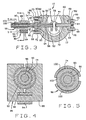
- Figure 3 is a cross section view of the GDCS check valve shown in Figure 1.
- Figure 4 is a cross section view through line 4-4 shown in Figure 3.
- Figure 5 is a cross section view through line 5-5 shown in Figure 3.
- FIG. 1 is a cross section view of a GDCS check valve 10 in accordance with one embodiment of the present invention.
- Check valve 10 is particularly suitable for use in a gravity driven cooling system of a nuclear reactor, however, valve 10 can be used in other applications. Therefore, although valve 10 is sometimes described herein in the context of a nuclear reactor, it should be understood that valve 10 can be used in many other applications.
- check valve 10 includes a valve body 12 and a disk assembly 14.
- Valve body 12 has a coolant flow channel 16 extending therethrough and a valve body seat 18 on an inner surface thereof.
- Coolant flow channel 16 includes an inlet end 20 and an outlet end 22.
- Valve body 12 also includes a maintenance opening 24 to enable removal, repair and replacement of disk assembly 14.
- a threaded stud 26 is secured, such as by a press fit, within and extends from an opening 28 in valve body 12 and a removable cover 30 having an opening 32 which aligns with threaded stud 26 is secured to valve body 12 and closes opening 24.
- a nut 34 engages threaded stud 26 to maintain cover 30 over opening 24.
- a gasket 36 attached to cover 30 facilitates sealing opening 24.
- Disk assembly 14 includes a counterweight 38 having a dome portion 40, a flange 42 and a main body portion 44. Disk assembly 14 also includes a disk base 46. Counterweight 38 is secured to disk base 46 and disk base 46 has a seat 48 for seating with valve body seat 18. When disk assembly 14 is in a closed position (not shown), disk base seat is seated 48 on valve body seat 18 to resist coolant flow in a direction from valve outlet end 22 to valve inlet end 20.
- a first hinge pin member 50 also is shown in Figure 1. Disk assembly 14 is rotatable about first hinge pin member 50. As described hereinafter in more detail, first hinge pin member 50 is secured to valve body 12.
- disk assembly 14 is about 15 degrees open as shown in Figure 1. Having disk assembly 14 normally open at about 15 degrees under such conditions is achieved by selecting the location for first hinge pin member 50 relative to the center of gravity of disk assembly 14.
- disk assembly 14 is normally about 15 degrees open as shown in Figure 1, disk assembly 14 is rotatable to about 60 degrees open as shown in Figure 2. By allowing disk assembly 14 to open to about 60 degrees, and under conditions in which coolant water must be quickly supplied to the reactor pressure vessel, disk assembly 14 can present minimal resistance to coolant flow.
- valve disk assembly 14 closes by rotating on first hinge pin member 50 so that disk seat 48 seats on valve body seat 18. Under such circumstance, valve disk seat 48 and valve body seat 18 form a coolant resistant seal to prevent the flow of coolant in the direction from valve outlet end 22 to valve inlet end 20.
- disk assembly 14 When closing, disk assembly 14 rotates quickly which reduces loud, potentially damaging slamming and vibration noises which typically occur when high velocity reverse flow is allowed to build up before completion of valve closing.
- disk assembly dome portion 40 facilitates avoiding hesitation of disk motion while closing, which is common with flat valve disks.
- first hinge pin 50 is located close to the center of gravity of disk assembly 14 and the disk assembly surfaces are open to the line fluid so that no dashpot action delays closing.
- Figure 3 is a cross section view of check valve shown in Figure 1.
- first hinge pin member 50 extends partially through counterweight main body portion 44 and is engaged to a first disk pin insert 52.
- Disk assembly 14 is rotatable relative to first hinge pin member 50.
- a bore 54 extends through first hinge pin member 50, and a shaft 56 extends through first hinge pin member bore 54 and is connected at a first end 58 to first disk pin insert 52.
- Shaft 56 is rotatable relative to first hinge pin member 50.
- a second hinge pin member 60 is secured to valve body 12 and extends through valve body 12.
- a flange 62 of second hinge pin member 60 is tightly pressed against valve body 12 by a retainer 64 engaged to valve body 12 by bolts 66 which extend into openings 68 in valve body 12 through openings 70 in retainer 64.
- a second disk pin insert 72 is secured within counterweight main body portion 44, and second disk pin insert 72 is engaged to second disk pin member 60.
- First and second disk pin inserts 52 and 72 are integral with main body portion 44.
- the interface surfaces between inserts 52 and 54 and pin members 50 and 60 are coated with, for example, a cobalt-based alloy to form bearing surfaces to prevent disk assembly 14 from freezing and to keep friction low.
- Disk assembly 14 is rotatable relative to first and second hinge pin members 50 and 60.
- An elongate housing 74 including a flange portion 76 and extension 78 is secured to valve body 12 by aligning openings 80 in flange portion 76 with openings 82 in valve body 12 and tightening bolts 84 in aligned openings 80 and 82.
- Housing extension 78 is press fit into engagement with first hinge pin member 50.
- Shaft 56 extends from first disk pin insert 52 through first hinge pin member 50 and within housing 74.
- Valve 10 includes a motor 86 having a stator frame 88 and a motor armature 90. Armature 90 is located within housing 74, and motor armature 90 and shaft 56 extend through a stator bore 92 in stator frame 88. Motor armature 90 and shaft 56 are rotatable relative to stator frame 88. A stator winding 94 energizable to generate a rotating magnetic field extends through a slot 96 formed in stator frame 88.
- An encoder 98 including an encoder shoe 100 also is mounted with respect to housing 74 so that armature 90 and shaft 56 extend through an opening 102 in encoder shoe 100.
- Encoder shoe 102 is constructed of magnetic material and generates a magnetic signal representative of the motion of magnetic armature 90.
- Detection circuitry (not shown), which is well known in the encoder art, is coupled to encoder 98 to provide a worker with an indication as to the direction and amount of rotation of armature 90.
- Figure 4 is a cross section view through line 4-4 shown in Figure 3. More specifically, Figure 4 is a cross section view through motor 86.
- motor 86 includes stator frame 88 and motor armature 90. Armature 90 and shaft 56 extend through stator bore 92 in stator frame 88. Stator winding 94 extends through slot 96 formed in stator frame 88.
- Figure 5 is a cross section view through line 5-5 shown in Figure 3. More specifically, Figure 5 is a cross section view through encoder 98.
- Encoder 98 includes shoes 100 which generate magnetic signals representative of the motion of armature 90.
- Detection circuitry (not shown) coupled to shoes 100 provides the worker with an indication as to the direction and amount of rotation of armature 90.
- GDCS check valve 10 can be tested while the reactor is in operation, rather than only during refueling outages, and such testing will not interfere with valve operation if valve 10 is required to function. More specifically, at any time during reactor operation, and when it is desired to test the operability of check valve 10, stator winding 94 is energized which causes armature 90 to rotate. Disk assembly 14 can be fully rotated to its full open position, e.g., 60 degrees open, by energizing motor winding 94 in a first pole configuration, e.g., a first winding lead is energized positive and a second winding lead is energized negative.
- stator winding 94 is energized which causes armature 90 to rotate.
- Disk assembly 14 can be fully rotated to its full open position, e.g., 60 degrees open, by energizing motor winding 94 in a first pole configuration, e.g., a first winding lead is energized positive and a second winding lead is energize
- Disk assembly 14 can also be fully rotated to its full closed position by energizing motor winding 94 in a second pole configuration, e.g., the first winding lead is energized negative and the second winding lead is energized positive. If at any time while performing such testing during reactor operation, the GDCS squib valve fires, then valve 10 closes. That is, the torque provided by motor 86 is not large enough to overcome the force of the RPV backpressure.
- GDCS disk assembly 14 can be stroked over its entire range of motion to ensure that valve 10 has a full range of operability. By stroking assembly 14 over its entire range of motion, valve 10 can be fully tested to enable identification of all possible failures.
Landscapes
- Engineering & Computer Science (AREA)
- General Engineering & Computer Science (AREA)
- Mechanical Engineering (AREA)
- Physics & Mathematics (AREA)
- Plasma & Fusion (AREA)
- High Energy & Nuclear Physics (AREA)
- Check Valves (AREA)
- Indication Of The Valve Opening Or Closing Status (AREA)
Claims (9)
- Rückschlagventil (10) zur Verwendung in einem Schwerkraft-getriebenen Kühlsystem eines Kernreaktors, wobei das Rückschlagventil (10) umfasst:einen Ventilkörper (12) mit einem sich hindurch erstreckenden Kühlmittel-Strömungskanal (16) und einem Ventilkörpersitz (18) auf einer inneren Oberfläche davon, wobei der Kühlmittel-Strömungskanal (16) ein Einlassende (20) und ein Auslassende (22) umfasst;eine Scheiben-Baueinheit (14), umfassend ein Gegengewicht (38) und eine Scheibenbasis (46), wobei das Gegengewicht (38) an der Scheibenbasis (46) befestigt ist, die Scheibenbasis (46) einen Scheibenbaueinheitssitz (48) zum Anliegen an dem Ventilkörpersitz (18) umfasst, um einer Kühlmittel-Strömung vom Auslassende (22) zum Einlassende (20) zu widerstehen, wobei die Schelben-Baueinheit (14) weiter einen ersten Scheiben-Stifteinsatz (52) umfasst;einen ersten Gelenkstift (50), der sich zumindest teilweise durch die Scheiben-Baueinheit (14) erstreckt und rotationsmäßig mit dem ersten Scheiben-Stifteinsatz (52) in Eingriff steht, wobei die Scheiben-Baueinheit (14) mit Bezug auf den ersten Gelenkstift (50) drehbar ist, wobei sich eine Bohrung (54) durch den ersten Gelenkstift (50) erstreckt;einen sich durch den ersten Gelenkstift (50) erstreckenden Schaft (56), der an einem ersten Ende (58) mit dem ersten Scheiben-Stifteinsatz (52) verbunden ist, wobei der Schaft (56) mit Bezug auf den ersten Gelenkstift (50) drehbar ist undeinen Motor (86), der einen Statorrahmen (88) umfasst, der eine Statorbohrung (92) aufweist, eine innerhalb der Statorbohrung (92) drehbar angeordnete Armatur (90), wobei der Schaft (56) mit der Armatur (90) verbunden und drehbar damit ist, wobei die durch den Motor (86) bereitgestellte Drehkraft nicht groß genug ist, um die durch die Kühlmittel-Strömung auf die Scheiben Baueinheit (14) ausgeübte Kraft zu überwinden.
- Rückschlagventil (10) gemäß Anspruch 1, worin sich eine Wartungsöffnung (24) durch den Ventilkörper (12) erstreckt und das Rückschlagventil (10) weiter einen entfernbaren Deckel (30) umfasst, der an dem Ventilkörper (12) befestigt ist und die Öffnung (24) schließt.
- Rückschlagventil (10) gemäß Anspruch 1, weiter umfassend einen zweiten Gelenkstift (60), wobei der zweite Gelenkstift (60) an dem Ventilkörper (12) befestigt ist und sich durch eine zweite Gelenkstift-Öffnung in den Ventilkörper (12) erstreckt.
- Rückschlagventil (10) gemäß Anspruch 3, worin die Scheiben-Baueinheit (14) weitet einen zweiten Scheiben-Stifteinsatz (72) umfasst, der innerhalb des Gegengewichtes (38) gesichert ist, wobei der zweite Scheiben-Stifteinsatz (72) mit dem zweiten Gelenkstift (60) in Eingriff steht, wobei die Scheiben-Baueinheit (14) mit Bezug auf den zweiten Gelenkstift (60) drehbar ist.
- Rückschlagventil (10) gemäß Anspruch 1, weiter umfassend ein Gehäuse (74), das an dem Ventilkörper (12) befestigt ist, wobei das Gehäuse (74) einen ersten Endpresssitz in Eingriff mit dem ersten Gelenkstift (50) umfasst, wobei sich der Schaft (56) von dem ersten Scheiben-Stifteinsatz (52) durch den ersten Gelenkstift (50) und innerhalb des Gehäuses (74) erstreckt.
- Rückschlagventil (10) gemäß Anspruch 5, worin die Motor-Armatur (90) innerhalb des Gehäuses (74) angeordnet ist.
- Rückschlagventil (10) gemäß Anspruch 6, worin das Gehäuse (74), die Motor-Armatur (90) und der Schaft (56) sich durch die Statorbohrung (92) in dem Statorrahmen (88) erstrecken.
- Rückschlagventil (10) gemäß Anspruch 7, weiter umfassend einen Kodierer (98), der einen Kodiererschuh (100) umfasst, und worin sich das Gehäuse (74), die Armatur (90) und der Schaft (56) durch den Kodiererschuh (100) erstrecken.
- Rückschlagventil (10) gemäß Anspruch 1, worin der Motor (86) weiter eine Stator-Wicklung (94) umfasst, die mit Energie versorgbar ist, um ein rotierendes Magnetfeld zu erzeugen, das mit einem Magnetfeld der Armatur (90) koppelt und die Rotation der Armatur (90) verursacht.
Applications Claiming Priority (2)
| Application Number | Priority Date | Filing Date | Title |
|---|---|---|---|
| US634845 | 1996-04-19 | ||
| US08/634,845 US5941278A (en) | 1996-04-19 | 1996-04-19 | Check valve |
Publications (3)
| Publication Number | Publication Date |
|---|---|
| EP0802358A2 EP0802358A2 (de) | 1997-10-22 |
| EP0802358A3 EP0802358A3 (de) | 1998-05-06 |
| EP0802358B1 true EP0802358B1 (de) | 2002-11-20 |
Family
ID=24545397
Family Applications (1)
| Application Number | Title | Priority Date | Filing Date |
|---|---|---|---|
| EP97302657A Expired - Lifetime EP0802358B1 (de) | 1996-04-19 | 1997-04-18 | Rückschlagventil |
Country Status (4)
| Country | Link |
|---|---|
| US (1) | US5941278A (de) |
| EP (1) | EP0802358B1 (de) |
| JP (1) | JP3983846B2 (de) |
| DE (1) | DE69717186T2 (de) |
Families Citing this family (4)
| Publication number | Priority date | Publication date | Assignee | Title |
|---|---|---|---|---|
| CN102384288A (zh) * | 2010-09-03 | 2012-03-21 | 瑞晶电子股份有限公司 | 双向流动式逆止阀及超纯水系统 |
| ITVI20110151A1 (it) * | 2011-06-09 | 2012-12-10 | Tyco Valves & Controls S R L | Valvole di non ritorno e sistemi e metodi di operazione delle stesse |
| US10036373B2 (en) | 2014-03-11 | 2018-07-31 | Ge-Hitachi Nuclear Energy Americas Llc | Thermal pumping via in situ pipes and apparatus including the same |
| HUE052303T2 (hu) * | 2015-07-13 | 2021-04-28 | Univ Tsinghua | Terelõlemez szerkezet a csatorna számára |
Family Cites Families (13)
| Publication number | Priority date | Publication date | Assignee | Title |
|---|---|---|---|---|
| US3106220A (en) * | 1961-09-13 | 1963-10-08 | Atwood & Morrill Co Inc | Check valve, with dashpot |
| US3602254A (en) * | 1970-01-30 | 1971-08-31 | Pratt Co Henry | Valve position indicating system |
| US3883111A (en) * | 1973-09-24 | 1975-05-13 | Acf Ind Inc | Clapper-type check valve |
| DE2724007A1 (de) * | 1977-05-27 | 1978-12-07 | Wurzer Lothar | Absperr- oder rueckschlagklappe |
| US4618824A (en) * | 1984-07-16 | 1986-10-21 | Westinghouse Electric Corp. | Method of testing the operability of check valves |
| US5154080A (en) * | 1986-10-29 | 1992-10-13 | Westinghouse Electric Corp. | Integrated check valve testing system |
| FR2618517B1 (fr) * | 1987-07-20 | 1989-11-17 | Trouvay & Cauvin Ets | Robinet-clapet |
| US5140263A (en) * | 1990-04-20 | 1992-08-18 | Liberty Technology Center, Inc. | System for determining position of an internal, movable conductive element |
| US5193568A (en) * | 1991-06-20 | 1993-03-16 | Martin Marietta Energy Systems, Inc. | Noninvasive valve monitor using alternating electromagnetic field |
| US5236011A (en) * | 1991-06-20 | 1993-08-17 | Martin Marietta Energy Systems, Inc. | Noninvasive valve monitor using constant magnetic and/or DC electromagnetic field |
| US5144977A (en) * | 1991-06-20 | 1992-09-08 | Dresser Industries, Inc. | Fluid valve with actuation sensor |
| US5295503A (en) * | 1992-10-02 | 1994-03-22 | Central Sprinkler Corporation | Modular valve for a building standpipe |
| DE4445100C2 (de) * | 1994-12-17 | 2002-11-21 | Gerd Hoermansdoerfer | Schaltbares Drosselklappensystem |
-
1996
- 1996-04-19 US US08/634,845 patent/US5941278A/en not_active Expired - Lifetime
-
1997
- 1997-04-16 JP JP09781897A patent/JP3983846B2/ja not_active Expired - Lifetime
- 1997-04-18 EP EP97302657A patent/EP0802358B1/de not_active Expired - Lifetime
- 1997-04-18 DE DE69717186T patent/DE69717186T2/de not_active Expired - Fee Related
Also Published As
| Publication number | Publication date |
|---|---|
| EP0802358A2 (de) | 1997-10-22 |
| JPH1038107A (ja) | 1998-02-13 |
| DE69717186T2 (de) | 2003-07-24 |
| DE69717186D1 (de) | 2003-01-02 |
| JP3983846B2 (ja) | 2007-09-26 |
| EP0802358A3 (de) | 1998-05-06 |
| US5941278A (en) | 1999-08-24 |
Similar Documents
| Publication | Publication Date | Title |
|---|---|---|
| JP5775978B2 (ja) | 鉄道車両用急速排気弁と鉄道車両の配管システム | |
| US6250605B1 (en) | Valve actuator apparatus | |
| EP0629804B1 (de) | Fernsteuerungsverfahren zur Prüfung der Betriebsfähigkeit eines motorgesteuertes Ventils | |
| US20030098074A1 (en) | Valve | |
| US5372351A (en) | Manual override system for rotary magnetically operated valve | |
| US3701362A (en) | Position indicating butterfly valve | |
| US4930748A (en) | Shutoff and regulating valve | |
| US6648010B1 (en) | Check valve plate with anti-pressure surge device | |
| EP2084442A2 (de) | Einbauventilmechanismus mit drehbarem keil sowie montage- und demontageverfahren | |
| EP0802358B1 (de) | Rückschlagventil | |
| US7546849B2 (en) | Rotating bonded valve assembly | |
| TW515876B (en) | Valve with cartridge | |
| Upton et al. | Check valve | |
| EP2964985A1 (de) | Doppelplatten-rückschlagventilanordnung mit steigender spindel | |
| US5224829A (en) | Rotatable valve having upper and lower parts | |
| JPH1061798A (ja) | ウェハー形逆止弁 | |
| GB2278905A (en) | Emergency shutdown valve | |
| KR102275681B1 (ko) | 밸브축 록킹장치를 갖는 버터플라이밸브 | |
| RU2821688C1 (ru) | Клапан-отсекатель | |
| US20060207662A1 (en) | Pressure relief valve | |
| KR100363229B1 (ko) | 복합 기능 안전밸브 | |
| KR100768529B1 (ko) | 상수도용 고무 디스크의 변형 방지 기능을 갖는 역지밸브 | |
| Ortega et al. | Improving Operations of Inoperable Valves | |
| Clark et al. | Effects of aging and service wear on main steam isolation valves and valve operators | |
| Farrell et al. | A Case Study: Balanced Globe Valve Load Sensitive Behavior Upon Opening |
Legal Events
| Date | Code | Title | Description |
|---|---|---|---|
| PUAI | Public reference made under article 153(3) epc to a published international application that has entered the european phase |
Free format text: ORIGINAL CODE: 0009012 |
|
| AK | Designated contracting states |
Kind code of ref document: A2 Designated state(s): CH DE FI LI SE |
|
| PUAL | Search report despatched |
Free format text: ORIGINAL CODE: 0009013 |
|
| AK | Designated contracting states |
Kind code of ref document: A3 Designated state(s): CH DE FI LI SE |
|
| 17P | Request for examination filed |
Effective date: 19981106 |
|
| GRAG | Despatch of communication of intention to grant |
Free format text: ORIGINAL CODE: EPIDOS AGRA |
|
| 17Q | First examination report despatched |
Effective date: 20020416 |
|
| GRAG | Despatch of communication of intention to grant |
Free format text: ORIGINAL CODE: EPIDOS AGRA |
|
| GRAH | Despatch of communication of intention to grant a patent |
Free format text: ORIGINAL CODE: EPIDOS IGRA |
|
| GRAH | Despatch of communication of intention to grant a patent |
Free format text: ORIGINAL CODE: EPIDOS IGRA |
|
| GRAA | (expected) grant |
Free format text: ORIGINAL CODE: 0009210 |
|
| AK | Designated contracting states |
Kind code of ref document: B1 Designated state(s): CH DE FI LI SE |
|
| REG | Reference to a national code |
Ref country code: CH Ref legal event code: NV Representative=s name: SERVOPATENT GMBH Ref country code: CH Ref legal event code: EP |
|
| REF | Corresponds to: |
Ref document number: 69717186 Country of ref document: DE Date of ref document: 20030102 |
|
| PGFP | Annual fee paid to national office [announced via postgrant information from national office to epo] |
Ref country code: SE Payment date: 20030422 Year of fee payment: 7 Ref country code: CH Payment date: 20030422 Year of fee payment: 7 |
|
| PGFP | Annual fee paid to national office [announced via postgrant information from national office to epo] |
Ref country code: FI Payment date: 20030423 Year of fee payment: 7 |
|
| PGFP | Annual fee paid to national office [announced via postgrant information from national office to epo] |
Ref country code: DE Payment date: 20030430 Year of fee payment: 7 |
|
| PLBE | No opposition filed within time limit |
Free format text: ORIGINAL CODE: 0009261 |
|
| STAA | Information on the status of an ep patent application or granted ep patent |
Free format text: STATUS: NO OPPOSITION FILED WITHIN TIME LIMIT |
|
| 26N | No opposition filed |
Effective date: 20030821 |
|
| PG25 | Lapsed in a contracting state [announced via postgrant information from national office to epo] |
Ref country code: FI Free format text: LAPSE BECAUSE OF NON-PAYMENT OF DUE FEES Effective date: 20040418 |
|
| PG25 | Lapsed in a contracting state [announced via postgrant information from national office to epo] |
Ref country code: SE Free format text: LAPSE BECAUSE OF NON-PAYMENT OF DUE FEES Effective date: 20040419 |
|
| PG25 | Lapsed in a contracting state [announced via postgrant information from national office to epo] |
Ref country code: LI Free format text: LAPSE BECAUSE OF NON-PAYMENT OF DUE FEES Effective date: 20040430 Ref country code: CH Free format text: LAPSE BECAUSE OF NON-PAYMENT OF DUE FEES Effective date: 20040430 |
|
| PG25 | Lapsed in a contracting state [announced via postgrant information from national office to epo] |
Ref country code: DE Free format text: LAPSE BECAUSE OF NON-PAYMENT OF DUE FEES Effective date: 20041103 |
|
| EUG | Se: european patent has lapsed | ||
| REG | Reference to a national code |
Ref country code: CH Ref legal event code: PL |