EP0802294B1 - Pivotable leaf of the concealed type provided with means for automatically engaging and disengaging it with/from its guides - Google Patents
Pivotable leaf of the concealed type provided with means for automatically engaging and disengaging it with/from its guides Download PDFInfo
- Publication number
- EP0802294B1 EP0802294B1 EP97200995A EP97200995A EP0802294B1 EP 0802294 B1 EP0802294 B1 EP 0802294B1 EP 97200995 A EP97200995 A EP 97200995A EP 97200995 A EP97200995 A EP 97200995A EP 0802294 B1 EP0802294 B1 EP 0802294B1
- Authority
- EP
- European Patent Office
- Prior art keywords
- cylinder
- pins
- leaf
- angled
- guides
- Prior art date
- Legal status (The legal status is an assumption and is not a legal conclusion. Google has not performed a legal analysis and makes no representation as to the accuracy of the status listed.)
- Expired - Lifetime
Links
- 239000007787 solid Substances 0.000 claims description 11
- 238000004873 anchoring Methods 0.000 claims description 2
- 230000008901 benefit Effects 0.000 description 3
- 239000002023 wood Substances 0.000 description 3
- 230000009471 action Effects 0.000 description 2
- 239000011521 glass Substances 0.000 description 2
- 239000012780 transparent material Substances 0.000 description 2
- 241000638935 Senecio crassissimus Species 0.000 description 1
- 230000008859 change Effects 0.000 description 1
- 238000005034 decoration Methods 0.000 description 1
- 239000000463 material Substances 0.000 description 1
- 239000013585 weight reducing agent Substances 0.000 description 1
Images
Classifications
-
- E—FIXED CONSTRUCTIONS
- E05—LOCKS; KEYS; WINDOW OR DOOR FITTINGS; SAFES
- E05D—HINGES OR SUSPENSION DEVICES FOR DOORS, WINDOWS OR WINGS
- E05D15/00—Suspension arrangements for wings
- E05D15/56—Suspension arrangements for wings with successive different movements
- E05D15/58—Suspension arrangements for wings with successive different movements with both swinging and sliding movements
- E05D15/582—Suspension arrangements for wings with successive different movements with both swinging and sliding movements with horizontal swinging axis
-
- E—FIXED CONSTRUCTIONS
- E05—LOCKS; KEYS; WINDOW OR DOOR FITTINGS; SAFES
- E05D—HINGES OR SUSPENSION DEVICES FOR DOORS, WINDOWS OR WINGS
- E05D15/00—Suspension arrangements for wings
- E05D15/36—Suspension arrangements for wings moving along slide-ways so arranged that one guide-member of the wing moves in a direction substantially perpendicular to the movement of another guide member
- E05D15/38—Suspension arrangements for wings moving along slide-ways so arranged that one guide-member of the wing moves in a direction substantially perpendicular to the movement of another guide member for upwardly-moving wings, e.g. up-and-over doors
-
- E—FIXED CONSTRUCTIONS
- E05—LOCKS; KEYS; WINDOW OR DOOR FITTINGS; SAFES
- E05Y—INDEXING SCHEME ASSOCIATED WITH SUBCLASSES E05D AND E05F, RELATING TO CONSTRUCTION ELEMENTS, ELECTRIC CONTROL, POWER SUPPLY, POWER SIGNAL OR TRANSMISSION, USER INTERFACES, MOUNTING OR COUPLING, DETAILS, ACCESSORIES, AUXILIARY OPERATIONS NOT OTHERWISE PROVIDED FOR, APPLICATION THEREOF
- E05Y2900/00—Application of doors, windows, wings or fittings thereof
- E05Y2900/20—Application of doors, windows, wings or fittings thereof for furniture, e.g. cabinets
Definitions
- the present invention relates to a pivotable leaf of the concealed type provided with simple means which cause it to engage with and disengage from its guides without the aid of any tool.
- pivotable leaves of the concealed type consisting essentially of a rigid panel, having a substantially rectangular shape and made of either opaque or transparent material, provided on two opposite sides with at least two projecting pins engaging in recessed right-angled guides which allow sliding and pivoting of the said leaves.
- This type of leaf functions extremely well because it is sufficient to choose the shape, dimensions and the material from which the pins and guides are made in order to avoid any problems in terms of the sliding action.
- difficulty is still encountered during disassembly thereof should it be required to carry out an operation, for example replacement, for any reason, of the panels of the same leaves in order to replace broken or damaged parts or simply change a decorated panel with another one having a different decoration.
- a closure member for a piece of furniture comprises a perimetric frame, supporting a front panel, having two vertical side members each one carrying a guide and retainer assembly provided with two guide pins projecting into inwardly open tracks fastened to walls of said piece of furniture.
- a door of a cabinet is provided with two lateral bracket members, each one having two guide posts to be engaged in an associated L-shaped guide track incorporated in a wall of a piece of furniture.
- the bracket members are fastened to the door by means of a plurality of screws (see specifically the wood screw depicted in figure 6), so as to be able to assembly and disassembly the brackets to and from the door it is sufficient to screw down and unscrew, respectively, the wood screws into and out the door itself.
- this operation is troublesome and time consuming enough and also in this case there is not a very great advantage with respect to the prior approach of removing a wall.
- the system for engaging and disengaging sliding leaves of the concealed type comprises lateral right-angled guides and at least two pairs of pins, one pair for each smaller side of the leaf, the said pairs of pins in use being retractable for disengaging from a corresponding said lateral right-angled guide, the pins being provided with resilient means, is characterized in that the said pins are expandable telescopic pins whereby their resilient means ensure the expansion of the telescopic pins for their engagement in the said right-angled guides, the system furthermore comprising at least one relief in the form of a ramp, and whereby the said relief can be provided at the inner end of the travel path of a said right-angled guide occupying the bottom of said right-angled guide and extending until flush with the outside of the said right-angled guide.
- the lateral right-angled guides are inserted into small channels formed in the corresponding walls of furniture so as to be flush with the said walls.
- the telescopic pins consist of a first solid cylinder of smaller diameter inserted in a cylindrical cavity, having a substantially similar diameter, of a second cylinder of larger diameter, and a resilient means inserted between the first cylinder and the cylindrical cavity so as to allow expansion of the first solid cylinder with respect to the second cylinder of the larger diameter.
- the resilient means consists of a helical spring inserted between a narrow relief on the internal end of the first solid cylinder and a similar relief projecting from the bottom of the cylindrical cavity of the second cylinder of larger diameter.
- the second cylinder of larger diameter comprises, at the external end, an expanded collar having a diameter greater than that of the cylinder itself so as to allow improved seating and anchoring thereof.
- the right-angled guides 10 and 10a are formed by a rectangular channel member 12 and 12a, which is open at the top, consisting of two arms 14, 14a and 16, 16a connected together by a connecting piece 18 and 18a, bent at 90°.
- the arms 14 and 16, 14a and 16a comprise a rectangular recess 20, 20a defining the channel of each right-angled guide 10 and 10a.
- a telescopic pin 30 according to the present invention is formed.
- This pin consists of a first solid cylinder 32 and a second hollow cylinder 34 provided with a cylindrical cavity 36 designed to receive a resilient means, such as a spring 38, which remains secured between a narrow relief 40 present underneath the first solid cylinder 32 and a relief 42, also narrow, present on the bottom of the cylindrical cavity 36.
- the second hollow cylinder 34 is provided with an expanded collar 44 in the form of a flat flange directed towards the first solid cylinder 32 so as to favour seating and fixing of the second cylinder 34 in a suitable cavity of a frame member 50 forming part of a pivotable leaf served by the present invention, as can be seen in Figures 8 and 9.
- each of the telescopic pins 30 is inserted into suitable holes formed in the frame member 50 through a first profiled member 52 and a second profiled member 54 separated by a space 56 from the first profiled member 52, so as to define a substantially tubular frame member 50 for reasons of weight reduction (although it is not excluded that one could also use a frame which is solid or provided with different profiled members).
- the profiled member 54 houses in one of its internal channels a pane 58 of a panel forming part of a pivotable leaf, whereby said pane 58 may consist of opaque or transparent material, such as simple or decorated glass.
- Figure 10 which shows a leaf 62 in its position lowered so as to close an opening 64 of a piece of furniture
- the leaf 62 formed by the frame 50 surrounding the glass pane 58, is provided with telescopic pins, the ends of the solid cylinders 32a-d of which can be seen projecting and engaging into the arms 16 and 16a of the right-angled guides.
- the leaf 62 can be raised from the position shown in Figure 10 into that shown in Figure 11 where the pins 30, while remaining engaged with the ends of the solid cylinders inside the right-angled guides 10 and 10a, keep the leaf engaged in the guides so that said leaf is unable to come out of the opening 64 of the furniture housing it.
- Figure 8 shows a cylinder 32 of the pin 30 engaged in the channel-shaped recess 20 of the arm 14 of the guide 10.
- a substantially right-angled guide 110 of the type depicted in Figure 13 formed by a channel 112 consisting of two arms 114 and 116 connected by a connecting piece 118, bent at 90°, continuing with a front raised portion 117 joined by a curved piece 119 to the arm 114.
- the remainder is similar to the right-angled guide 10 of Figure 1, and in fact the numbering of its parts is similar to that of the guide 10 with the addition of the number "1" in front.
- disassembly insert 122 with its ramp 124 it is entirely similar to the insert 22 of Figures 1, 2 and 4, with the sole limitation that it is short enough not to interfere with the curved piece 119, but long enough to exceed the interaxial distances between the cylinders 32a and 32b or 32c and 32d (see Figure 10) in order to ensure reliable removal of the leaf 62 in the manner depicted in Figure 12.
- the invention functions as follows:
Landscapes
- Engineering & Computer Science (AREA)
- Mechanical Engineering (AREA)
- Supports Or Holders For Household Use (AREA)
- Legs For Furniture In General (AREA)
- Wing Frames And Configurations (AREA)
- Connection Of Plates (AREA)
- Helmets And Other Head Coverings (AREA)
- Footwear And Its Accessory, Manufacturing Method And Apparatuses (AREA)
- Chair Legs, Seat Parts, And Backrests (AREA)
- Holders For Apparel And Elements Relating To Apparel (AREA)
- Registering, Tensioning, Guiding Webs, And Rollers Therefor (AREA)
- Manual Feeding Of Sheets (AREA)
- Vehicle Waterproofing, Decoration, And Sanitation Devices (AREA)
- Operating, Guiding And Securing Of Roll- Type Closing Members (AREA)
Abstract
Description
- The present invention relates to a pivotable leaf of the concealed type provided with simple means which cause it to engage with and disengage from its guides without the aid of any tool.
- For a long time it has been known of pivotable leaves of the concealed type consisting essentially of a rigid panel, having a substantially rectangular shape and made of either opaque or transparent material, provided on two opposite sides with at least two projecting pins engaging in recessed right-angled guides which allow sliding and pivoting of the said leaves.
- This type of leaf functions extremely well because it is sufficient to choose the shape, dimensions and the material from which the pins and guides are made in order to avoid any problems in terms of the sliding action. However, although there may be no problems as regards operation of the leaves, difficulty is still encountered during disassembly thereof should it be required to carry out an operation, for example replacement, for any reason, of the panels of the same leaves in order to replace broken or damaged parts or simply change a decorated panel with another one having a different decoration.
- Hitherto, since the pins present on the leaves are usually incorporated in linear members fixed by means of screws to the sides of the said leaves, a part of the said screws always remaining covered by the guides, it is necessary, in order to perform disassembly of the leaves, to remove at least one wall of the piece of furniture containing the said leaves with the obvious drawback of extensive work requiring particularly skilful and specialized personnel, or else it is necessary to make holes in the guides and in the underlying walls of the furniture, for access to the said screws, whereby said holes are difficult to cover up and could negatively affect the aesthetic appearance of the furniture containing the leaves. A first attempt of a system for engaging and disengaging a sliding leaf and which system has the features of the preamble of claim 1 is disclosed by US-A-3,653,158 and depicted in figures 1 to 5 thereof. According to such a document, a closure member for a piece of furniture comprises a perimetric frame, supporting a front panel, having two vertical side members each one carrying a guide and retainer assembly provided with two guide pins projecting into inwardly open tracks fastened to walls of said piece of furniture. In order to help the disassembly of the closure member from the piece of furniture, the guide pins are engaged in retainer members fitted in a double wall of each vertical side member so as to can be disengaged from them only through a manual intervention by means of a suitable tool, such as a screwdriver, on a threaded portion of the pins themselves from the inside of the piece of furniture. This kind of intervention is almost as troublesome and time consuming as the removal of one wall of the piece of furniture and thus there is a very poor advantage with respect to the prior approach of removing a wall. A second attempt to overcome the same problem is disclosed by US-A-5,083,847 and particularly depicted in figures 1, 5 and 6 thereof. According to such a document, a door of a cabinet is provided with two lateral bracket members, each one having two guide posts to be engaged in an associated L-shaped guide track incorporated in a wall of a piece of furniture. The bracket members are fastened to the door by means of a plurality of screws (see specifically the wood screw depicted in figure 6), so as to be able to assembly and disassembly the brackets to and from the door it is sufficient to screw down and unscrew, respectively, the wood screws into and out the door itself. However also this operation is troublesome and time consuming enough and also in this case there is not a very great advantage with respect to the prior approach of removing a wall.
- For the reasons mentioned hereinabove, it has been necessary to devise the system for engaging and disengaging sliding leaves of the concealed type according to the present invention.
- Briefly stated, the system for engaging and disengaging sliding leaves of the concealed type, having rectangular shape, comprises lateral right-angled guides and at least two pairs of pins, one pair for each smaller side of the leaf, the said pairs of pins in use being retractable for disengaging from a corresponding said lateral right-angled guide, the pins being provided with resilient means, is characterized in that the said pins are expandable telescopic pins whereby their resilient means ensure the expansion of the telescopic pins for their engagement in the said right-angled guides, the system furthermore comprising at least one relief in the form of a ramp, and whereby the said relief can be provided at the inner end of the travel path of a said right-angled guide occupying the bottom of said right-angled guide and extending until flush with the outside of the said right-angled guide.
- Preferably, the lateral right-angled guides are inserted into small channels formed in the corresponding walls of furniture so as to be flush with the said walls.
- Preferably, the telescopic pins consist of a first solid cylinder of smaller diameter inserted in a cylindrical cavity, having a substantially similar diameter, of a second cylinder of larger diameter, and a resilient means inserted between the first cylinder and the cylindrical cavity so as to allow expansion of the first solid cylinder with respect to the second cylinder of the larger diameter.
- In particular, the resilient means consists of a helical spring inserted between a narrow relief on the internal end of the first solid cylinder and a similar relief projecting from the bottom of the cylindrical cavity of the second cylinder of larger diameter.
- Also in particular, the second cylinder of larger diameter comprises, at the external end, an expanded collar having a diameter greater than that of the cylinder itself so as to allow improved seating and anchoring thereof.
- The main features of the present invention shall be defined in particular in the claims forming the conclusive part of the present description. However, other features and advantages will emerge more clearly from the following detailed description of a preferred example of embodiment thereof, not to be considered limiting in any way, together with the accompanying drawings, in which:
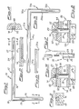
- Figure 1 is a side elevation view of a first right-angled guide used for leaves containing the present invention;
- Figure 2 is a partial sectioned view, of the same right-angled guide depicted in Figure 1, showing the relief which has the function of disengaging the telescopic pins of the leaves;
- Figure 3 is a sectional view, along the line 3-3 of Figure 1, of the right-angled guide;
- Figure 4 is a sectional view, along the line 4-4 of Figure 1, of the right-angled guide;
- Figure 5 is a side elevation view of a second right-angled guide used for leaves containing the present invention, which is specularly symmetrical with respect to the one depicted in Figure 1;
- Figure 6 is a partial sectional view of the same right-angled guide depicted in Figure 5, showing the relief which has the function of disengaging the telescopic pins of the leaves;
- Figure 7 is an exploded sectioned view of a telescopic pin used in the present invention;
- Figure 8 is a partial view illustrating a telescopic pin inserted in a leaf, emerging so as to engage with a right-angled guide;
- Figure 9 is a partial view illustrating a telescopic pin inserted in a leaf, retracting as a result of engagement with one of the reliefs which has the function of disengaging the telescopic pin;
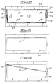
- Figure 10 is a front view, with parts removed, of a closed leaf containing the present invention;
- Figure 11 is a front view of a leaf, according to the present invention, in the pivoted or open position;
- Figure 12 is a front view showing how a leaf containing the present invention is disengaged after it has been pivoted;
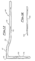
- Figure 13 is a side elevation view of a variant of a right-angled guide having a raised front zone connected to the remainder of a horizontal arm of the guide by means of a curved arch; and
- Figure 14 is a perspective view of a separate device for disengaging leaf pins from the corresponding right-angled guide.
- If we consider Figures 1 to 6 first of all, it can be seen that the right-
angled guides 10 and 10a are formed by arectangular channel member arms piece arms rectangular recess angled guide 10 and 10a. When the leaf is to be removed, it is possible to insert inside thearm insert 22, provided with a ramp-shaped joiningportion 24, having the function of disengaging the leaves, as described in detail further below. - If we consider Figure 7, it can be seen how a
telescopic pin 30 according to the present invention is formed. This pin consists of a firstsolid cylinder 32 and a secondhollow cylinder 34 provided with acylindrical cavity 36 designed to receive a resilient means, such as aspring 38, which remains secured between a narrow relief 40 present underneath the firstsolid cylinder 32 and arelief 42, also narrow, present on the bottom of thecylindrical cavity 36. The secondhollow cylinder 34 is provided with an expandedcollar 44 in the form of a flat flange directed towards the firstsolid cylinder 32 so as to favour seating and fixing of thesecond cylinder 34 in a suitable cavity of aframe member 50 forming part of a pivotable leaf served by the present invention, as can be seen in Figures 8 and 9. If we continue to examine Figures 8 and 9, it can be seen that each of thetelescopic pins 30 is inserted into suitable holes formed in theframe member 50 through a first profiledmember 52 and a second profiledmember 54 separated by aspace 56 from the first profiledmember 52, so as to define a substantiallytubular frame member 50 for reasons of weight reduction (although it is not excluded that one could also use a frame which is solid or provided with different profiled members). The profiledmember 54 houses in one of its internal channels apane 58 of a panel forming part of a pivotable leaf, whereby saidpane 58 may consist of opaque or transparent material, such as simple or decorated glass. - From an examination of Figures 10 to 12, together with Figures 8 and 9, it can be understood how a
pivotable leaf 62 is engaged in the right-angled guides 10 and 10a and how it can be disengaged therefrom. - As can be seen in particular in Figure 10, which shows a
leaf 62 in its position lowered so as to close anopening 64 of a piece of furniture, theleaf 62, formed by theframe 50 surrounding theglass pane 58, is provided with telescopic pins, the ends of thesolid cylinders 32a-d of which can be seen projecting and engaging into thearms - Obviously, the
leaf 62 can be raised from the position shown in Figure 10 into that shown in Figure 11 where thepins 30, while remaining engaged with the ends of the solid cylinders inside the right-angled guides 10 and 10a, keep the leaf engaged in the guides so that said leaf is unable to come out of theopening 64 of the furniture housing it. The reason for this can be fully understood by considering Figure 8 which shows acylinder 32 of thepin 30 engaged in the channel-shaped recess 20 of thearm 14 of theguide 10. - In order to obtain disengagement of the
cylinders 32 from theguides 10 or 10a, it is sufficient to merely move forwards the pivotable leaf until thecylinders 32 of thetelescopic pins 30 are located against therelief 22 introduced into thechannel 20 of the right-angled guide 10. In this case thecylinders 32 are gradually pushed by the ramp-shaped joiningportion 24 so as to retract inside thehollow cylinders 34 until their external end is located flush with the edges of thearm 14 of theguide 10. Since, as amply depicted by Figures 3, 4, 8 and 9, all the arms of the right-angled guide 10 are embedded in abody 60 of the furniture, for example made of wood, if acylinder 32 emerges from thechannel 20 as a result of being pushed by therelief 22, it is disengaged therefrom, thus allowing theleaf 62 to clear theguide 10 and thus making it disengageable from theopening 64 of the furniture and thus completely freed, as depicted in Figure 12. - Should leaves of particularly pronounced thickness be required, it is convenient to use a substantially right-
angled guide 110 of the type depicted in Figure 13 formed by achannel 112 consisting of twoarms piece 118, bent at 90°, continuing with a front raisedportion 117 joined by acurved piece 119 to thearm 114. The remainder is similar to the right-angled guide 10 of Figure 1, and in fact the numbering of its parts is similar to that of theguide 10 with the addition of the number "1" in front. As for the disassembly insert 122 with itsramp 124, it is entirely similar to theinsert 22 of Figures 1, 2 and 4, with the sole limitation that it is short enough not to interfere with thecurved piece 119, but long enough to exceed the interaxial distances between thecylinders leaf 62 in the manner depicted in Figure 12. - The invention functions as follows:
- if it is required merely to tilt the
leaf 62, causing it to stay engaged inside the right-angled guides 10 and 10a, such that it does not come out from the furniture, it is sufficient to raise the said leaf for as long as one can feel it freely sliding. When one feels a resistance to the pivoting movement of the leaf, due to thecylinders 32 which engage with the bottoms of thearms channels - if it is required to separate the
leaf 62 from inside theopening 64 of the furniture, it is sufficient to merely introduce theinsert 22 into thechannel 12 of the right-angled guide 10, overcoming the resistance encountered when thefirst cylinder 32a meets the ramp-shaped joining portion of therelief 22, and continue pushing inwards until the second cylinder 32b meets the ramp-shaped joiningportion 24 of therelief 22; - at this point the two
cylinders 32a and 32b are in the conditions shown in Figure 9 so that thecylinders 32 of thetelescopic pins 30 emerge from the guides encountering thebody 60 of the furniture and theleaf 62 slides to one side, as shown in Figure 12, being freed completely from the walls of theopening 64. - Basically, in order to tilt the
leaf 62, it is sufficient to raise it until one feels a resistance to its movement and then a stopping action, while in order to disengage theleaf 62 from the walls of theopening 64, it is sufficient to introduce a relief-shaped insert 22 into thechannel 12 of the right-angled guide 10 and continue the same movement, overcoming the resistances which are progressively encountered, until theleaf 62 is entirely disengaged from the walls of theopening 64. - In order to re-introduce a removed leaf so that it engages in the right-
angled guides 10 and 10a, it is sufficient to position thevertical leaf 62 in front of theopening 64, causing for example acylinder 32a to enter into thecorresponding arm 16 of the right-angled guide 10 and pressing with a finger thecylinder 32c so as to make it enter against a wall of theopening 64. At this point, one continues to raise theleaf 62 until thecylinder 32c has entered into thechannel 20a of thearm 16a of the right-angled guide 10a. One then raises theleaf 62 until thesecond cylinders 32b and 32d are also located against the walls of theopening 64, between which they would easily enter if simply pressed with one's fingers. Once thecylinders 32b and 32d have also entered between the walls of theopening 64, it is sufficient to continue to raise theleaf 62 so as to cause also theselatter cylinders 32b and 32d to enter into thechannels arms leaf 62 is engaged and positioned as shown in Figure 10. - The above description is just an embodiment of the present invention, to which persons skilled in this particular art may make logical and equivalent changes to be considered herein covered, as defined in the appended claims.
Claims (5)
- System for engaging and disengaging sliding leaves (62) of the concealed type having rectangular shape, the system comprising lateral right-angled guides (10, 10a) and at least two pairs of pins (30), one pair for each smaller side of the leaf (62), the said pairs of pins (30) in use being retractable for disengaging from a corresponding said lateral right-angled guide (10, 10a), the pins (30) being provided with resilient means (38),
characterized in that,the said pins (30) are expandable telescopic pins whereby their resilient means (38) ensure the expansion of the telescopic pins for their engagement in the said right-angled guides (10, 10a),the system furthermore comprising at least one relief (22) in the form of a ramp(24), and whereby the said relief (22) can be provided at the inner end of the travel path of a said right-angled guide (10, 10a) occupying the bottom of said right-angled guide (10, 10a) and extending until flush with the outside of the said right-angled guide (10, 10a). - System according to Claim 1, characterized in that the lateral right-angled guides (10, 10a) are inserted in small channels formed in the corresponding walls (60) of the furniture so as to be flush with the said walls (60).
- System according to the Claims 1 or 2, characterized in that the telescopic pins (30) consist of a first solid cylinder (32) of smaller diameter inserted in a cylindrical cavity (36), having a substantially similar diameter, of a second cylinder (34) of larger diameter, and a resilient means (38) inserted between the first cylinder (32) and the cylindrical cavity (36) so as to allow expansion of the first cylinder (32) with respect to the second cylinder (34).
- System according to Claim 3, characterized in that the resilient means consists of a helical spring (38) inserted between a narrow relief (40) on the internal end of the first solid cylinder (32) and a similar relief (42) projecting from the bottom of the cylindrical cavity (36) of the second cylinder (34) of larger diameter.
- System according to Claims 3 or 4, characterized in that the second cylinder (34) of larger diameter comprises, at the external end, an expanded collar (44) having a diameter greater than that of the cylinder itself (34) so as to allow improved seating and anchoring thereof.
Applications Claiming Priority (2)
| Application Number | Priority Date | Filing Date | Title |
|---|---|---|---|
| ITMI960291U | 1996-04-16 | ||
| IT1996MI000291U IT240600Y1 (it) | 1996-04-16 | 1996-04-16 | Antina ribaltabile a scomparsa munita di mezzi automatici diimpegno e disimpegno della medesima in sue guide. |
Publications (2)
| Publication Number | Publication Date |
|---|---|
| EP0802294A1 EP0802294A1 (en) | 1997-10-22 |
| EP0802294B1 true EP0802294B1 (en) | 2000-07-12 |
Family
ID=11373289
Family Applications (1)
| Application Number | Title | Priority Date | Filing Date |
|---|---|---|---|
| EP97200995A Expired - Lifetime EP0802294B1 (en) | 1996-04-16 | 1997-04-04 | Pivotable leaf of the concealed type provided with means for automatically engaging and disengaging it with/from its guides |
Country Status (6)
| Country | Link |
|---|---|
| EP (1) | EP0802294B1 (en) |
| AT (1) | ATE194681T1 (en) |
| DE (1) | DE69702474T2 (en) |
| ES (1) | ES1036861Y (en) |
| IT (1) | IT240600Y1 (en) |
| PT (1) | PT802294E (en) |
Family Cites Families (3)
| Publication number | Priority date | Publication date | Assignee | Title |
|---|---|---|---|---|
| US3653158A (en) * | 1970-06-22 | 1972-04-04 | Westinghouse Electric Corp | Arrangement for supporting a closure member from a track |
| DE3709331A1 (en) * | 1987-03-21 | 1988-09-29 | Licentia Gmbh | Door bearing for refrigerators and/or freezers |
| US5083847A (en) * | 1991-01-28 | 1992-01-28 | Transfer Flow International, Inc. | Pocket door attachment fitting for a cabinet |
-
1996
- 1996-04-16 IT IT1996MI000291U patent/IT240600Y1/it active
-
1997
- 1997-04-04 EP EP97200995A patent/EP0802294B1/en not_active Expired - Lifetime
- 1997-04-04 AT AT97200995T patent/ATE194681T1/en active
- 1997-04-04 PT PT97200995T patent/PT802294E/en unknown
- 1997-04-04 DE DE69702474T patent/DE69702474T2/en not_active Expired - Fee Related
- 1997-04-04 ES ES09700852U patent/ES1036861Y/en not_active Expired - Fee Related
Also Published As
| Publication number | Publication date |
|---|---|
| ITMI960291U1 (en) | 1997-10-16 |
| DE69702474D1 (en) | 2000-08-17 |
| PT802294E (en) | 2000-11-30 |
| EP0802294A1 (en) | 1997-10-22 |
| ATE194681T1 (en) | 2000-07-15 |
| ES1036861Y (en) | 1998-04-01 |
| IT240600Y1 (it) | 2001-04-02 |
| ES1036861U (en) | 1997-11-16 |
| DE69702474T2 (en) | 2001-04-19 |
Similar Documents
| Publication | Publication Date | Title |
|---|---|---|
| CA2115616C (en) | Corner assembly and frame comprising such assembly | |
| US4878530A (en) | Bathroom panel | |
| AU2743992A (en) | A raisable-curtain door providing good heat insulation | |
| US5839228A (en) | Swing-up sliding door arrangement | |
| US5423144A (en) | Window with sliding and pivoted panes | |
| CA2522999C (en) | Tilt-latch and window sash assembly | |
| US4910916A (en) | Sliding door fitting | |
| US4838332A (en) | Swinging screen door for sliding glass doors | |
| JPH08175171A (en) | Window glass cassette for vehicle doors and method of mounting such cassette | |
| GB2295636A (en) | Threshold for sliding window/door | |
| JPH01304290A (en) | Slat shade actuator | |
| GB2301621A (en) | Window or like stay | |
| EP0802294A1 (en) | Pivotable leaf of the concealed type provided with means for automatically engaging and disengaging it with/from its guides | |
| CA1267184A (en) | Door support devices for cupboards | |
| EP0209386A2 (en) | Wardrobe or other container with folding doors | |
| CA2836920C (en) | Venetian type blind operator | |
| WO1996004834A1 (en) | Screen of the type having two or more overlapping sliding leaves | |
| EP0538181A1 (en) | A sliding door arrangement for a shower or bath cubicle | |
| EP1741863A1 (en) | Cupboard front with coplanar closing sliding doors | |
| JPH01295984A (en) | Closing device | |
| EP0235952A1 (en) | A window with an adjustable slat blind and an insect screen mountable internally thereof | |
| EP4071315A1 (en) | System for partitioning a space | |
| GB2292964A (en) | Door finger guard | |
| GB2281580B (en) | Draught proofing sliding sash windows | |
| JPH0725425Y2 (en) | Folding door structure |
Legal Events
| Date | Code | Title | Description |
|---|---|---|---|
| PUAI | Public reference made under article 153(3) epc to a published international application that has entered the european phase |
Free format text: ORIGINAL CODE: 0009012 |
|
| AK | Designated contracting states |
Kind code of ref document: A1 Designated state(s): AT BE DE FR NL PT |
|
| 17P | Request for examination filed |
Effective date: 19980415 |
|
| 17Q | First examination report despatched |
Effective date: 19981230 |
|
| GRAG | Despatch of communication of intention to grant |
Free format text: ORIGINAL CODE: EPIDOS AGRA |
|
| GRAG | Despatch of communication of intention to grant |
Free format text: ORIGINAL CODE: EPIDOS AGRA |
|
| GRAH | Despatch of communication of intention to grant a patent |
Free format text: ORIGINAL CODE: EPIDOS IGRA |
|
| GRAH | Despatch of communication of intention to grant a patent |
Free format text: ORIGINAL CODE: EPIDOS IGRA |
|
| GRAA | (expected) grant |
Free format text: ORIGINAL CODE: 0009210 |
|
| AK | Designated contracting states |
Kind code of ref document: B1 Designated state(s): AT BE DE FR NL PT |
|
| REF | Corresponds to: |
Ref document number: 194681 Country of ref document: AT Date of ref document: 20000715 Kind code of ref document: T |
|
| REF | Corresponds to: |
Ref document number: 69702474 Country of ref document: DE Date of ref document: 20000817 |
|
| ET | Fr: translation filed | ||
| REG | Reference to a national code |
Ref country code: PT Ref legal event code: SC4A Free format text: AVAILABILITY OF NATIONAL TRANSLATION Effective date: 20000830 |
|
| PGFP | Annual fee paid to national office [announced via postgrant information from national office to epo] |
Ref country code: AT Payment date: 20010328 Year of fee payment: 5 |
|
| PGFP | Annual fee paid to national office [announced via postgrant information from national office to epo] |
Ref country code: BE Payment date: 20010417 Year of fee payment: 5 |
|
| PGFP | Annual fee paid to national office [announced via postgrant information from national office to epo] |
Ref country code: DE Payment date: 20010427 Year of fee payment: 5 |
|
| PGFP | Annual fee paid to national office [announced via postgrant information from national office to epo] |
Ref country code: NL Payment date: 20010430 Year of fee payment: 5 Ref country code: FR Payment date: 20010430 Year of fee payment: 5 |
|
| PLBE | No opposition filed within time limit |
Free format text: ORIGINAL CODE: 0009261 |
|
| STAA | Information on the status of an ep patent application or granted ep patent |
Free format text: STATUS: NO OPPOSITION FILED WITHIN TIME LIMIT |
|
| 26N | No opposition filed | ||
| PG25 | Lapsed in a contracting state [announced via postgrant information from national office to epo] |
Ref country code: AT Free format text: LAPSE BECAUSE OF NON-PAYMENT OF DUE FEES Effective date: 20020404 |
|
| PG25 | Lapsed in a contracting state [announced via postgrant information from national office to epo] |
Ref country code: BE Free format text: LAPSE BECAUSE OF NON-PAYMENT OF DUE FEES Effective date: 20020430 |
|
| PG25 | Lapsed in a contracting state [announced via postgrant information from national office to epo] |
Ref country code: NL Free format text: LAPSE BECAUSE OF NON-PAYMENT OF DUE FEES Effective date: 20021101 Ref country code: DE Free format text: LAPSE BECAUSE OF NON-PAYMENT OF DUE FEES Effective date: 20021101 |
|
| PG25 | Lapsed in a contracting state [announced via postgrant information from national office to epo] |
Ref country code: FR Free format text: LAPSE BECAUSE OF NON-PAYMENT OF DUE FEES Effective date: 20021231 |
|
| NLV4 | Nl: lapsed or anulled due to non-payment of the annual fee |
Effective date: 20021101 |
|
| REG | Reference to a national code |
Ref country code: FR Ref legal event code: ST |
|
| PGFP | Annual fee paid to national office [announced via postgrant information from national office to epo] |
Ref country code: PT Payment date: 20041001 Year of fee payment: 8 |
|
| PG25 | Lapsed in a contracting state [announced via postgrant information from national office to epo] |
Ref country code: PT Free format text: LAPSE BECAUSE OF NON-PAYMENT OF DUE FEES Effective date: 20051004 |