EP0802016A1 - Machine tool with rotating table - Google Patents
Machine tool with rotating table Download PDFInfo
- Publication number
- EP0802016A1 EP0802016A1 EP97101077A EP97101077A EP0802016A1 EP 0802016 A1 EP0802016 A1 EP 0802016A1 EP 97101077 A EP97101077 A EP 97101077A EP 97101077 A EP97101077 A EP 97101077A EP 0802016 A1 EP0802016 A1 EP 0802016A1
- Authority
- EP
- European Patent Office
- Prior art keywords
- machine tool
- table top
- lines
- adapter plate
- tool according
- Prior art date
- Legal status (The legal status is an assumption and is not a legal conclusion. Google has not performed a legal analysis and makes no representation as to the accuracy of the status listed.)
- Granted
Links
- 230000008878 coupling Effects 0.000 claims abstract description 23
- 238000010168 coupling process Methods 0.000 claims abstract description 23
- 238000005859 coupling reaction Methods 0.000 claims abstract description 23
- 239000012530 fluid Substances 0.000 abstract description 6
- 238000010276 construction Methods 0.000 description 6
- 238000011010 flushing procedure Methods 0.000 description 5
- 238000003754 machining Methods 0.000 description 3
- 238000001816 cooling Methods 0.000 description 2
- 239000010720 hydraulic oil Substances 0.000 description 2
- 238000012423 maintenance Methods 0.000 description 2
- 239000003921 oil Substances 0.000 description 2
- 239000003795 chemical substances by application Substances 0.000 description 1
- 239000002826 coolant Substances 0.000 description 1
- 230000002950 deficient Effects 0.000 description 1
- 238000005553 drilling Methods 0.000 description 1
- 238000009413 insulation Methods 0.000 description 1
- 239000004033 plastic Substances 0.000 description 1
Images

Classifications
-
- B—PERFORMING OPERATIONS; TRANSPORTING
- B23—MACHINE TOOLS; METAL-WORKING NOT OTHERWISE PROVIDED FOR
- B23Q—DETAILS, COMPONENTS, OR ACCESSORIES FOR MACHINE TOOLS, e.g. ARRANGEMENTS FOR COPYING OR CONTROLLING; MACHINE TOOLS IN GENERAL CHARACTERISED BY THE CONSTRUCTION OF PARTICULAR DETAILS OR COMPONENTS; COMBINATIONS OR ASSOCIATIONS OF METAL-WORKING MACHINES, NOT DIRECTED TO A PARTICULAR RESULT
- B23Q1/00—Members which are comprised in the general build-up of a form of machine, particularly relatively large fixed members
- B23Q1/0009—Energy-transferring means or control lines for movable machine parts; Control panels or boxes; Control parts
- B23Q1/0018—Energy-transferring means or control lines for movable machine parts; Control panels or boxes; Control parts comprising hydraulic means
- B23Q1/0027—Energy-transferring means or control lines for movable machine parts; Control panels or boxes; Control parts comprising hydraulic means between moving parts between which an uninterrupted energy-transfer connection is maintained
-
- B—PERFORMING OPERATIONS; TRANSPORTING
- B23—MACHINE TOOLS; METAL-WORKING NOT OTHERWISE PROVIDED FOR
- B23Q—DETAILS, COMPONENTS, OR ACCESSORIES FOR MACHINE TOOLS, e.g. ARRANGEMENTS FOR COPYING OR CONTROLLING; MACHINE TOOLS IN GENERAL CHARACTERISED BY THE CONSTRUCTION OF PARTICULAR DETAILS OR COMPONENTS; COMBINATIONS OR ASSOCIATIONS OF METAL-WORKING MACHINES, NOT DIRECTED TO A PARTICULAR RESULT
- B23Q1/00—Members which are comprised in the general build-up of a form of machine, particularly relatively large fixed members
- B23Q1/25—Movable or adjustable work or tool supports
- B23Q1/44—Movable or adjustable work or tool supports using particular mechanisms
- B23Q1/50—Movable or adjustable work or tool supports using particular mechanisms with rotating pairs only, the rotating pairs being the first two elements of the mechanism
- B23Q1/52—Movable or adjustable work or tool supports using particular mechanisms with rotating pairs only, the rotating pairs being the first two elements of the mechanism a single rotating pair
-
- Y—GENERAL TAGGING OF NEW TECHNOLOGICAL DEVELOPMENTS; GENERAL TAGGING OF CROSS-SECTIONAL TECHNOLOGIES SPANNING OVER SEVERAL SECTIONS OF THE IPC; TECHNICAL SUBJECTS COVERED BY FORMER USPC CROSS-REFERENCE ART COLLECTIONS [XRACs] AND DIGESTS
- Y10—TECHNICAL SUBJECTS COVERED BY FORMER USPC
- Y10T—TECHNICAL SUBJECTS COVERED BY FORMER US CLASSIFICATION
- Y10T74/00—Machine element or mechanism
- Y10T74/14—Rotary member or shaft indexing, e.g., tool or work turret
Definitions
- the present invention relates to a machine tool with a rotary table which has a table top which can be pivoted about an axis of rotation with respect to a machine frame, on the upper side of which lines coming from below the table top lead and which are connected to fixed supply connections.
- Such a machine tool is known from DE 83 16 776 U1.
- a junction box is firmly mounted on the turntable.
- Plug connections are provided in a side wall of the connection box, which is connected to the turntable in a manner fixed against relative rotation, while a rotary coupling is arranged on the upper side of the connection box, which is fixed relative to the turntable.
- the top of the junction box cover is connected to a tube passing through the table, which is fixed in space, ie does not follow the rotation of the table.
- Connection lines run from bottom to top in the tube, one of which is connected to the rotary coupling from below. Fluid supplied via the connecting line can be removed from the rotary coupling via a further line.
- the upper part of the connection box stops, while the line for removing the fluid rotates with the table via the rotary coupling. According to this publication, this rotation is possible because the rotary coupling lies centrally in the axis of rotation of the rotary table.
- the plug connections in the side wall of the connection box which rotates with the table are connected to lines which may be laid in multilayer loops in the interior of the connection box, so that they allow the turntable to be rotated with appropriate play or free space, the loops becoming detached. or wind up.
- Such a turntable is used in machine tools in which at least two workpieces are arranged on the top of the turntable and are offered for machining by turning the table top one after the other.
- the lines lead drilling and flushing oil, hydraulic oil or compressed air to the top of the turntable, in order to actuate a workpiece holder, for flushing during workpiece machining etc. to be used.
- These fluids are provided at fixed supply connections, which are connected via the lines to the top of the rotating table top.
- a line running centrally to the axis of rotation of the table top is connected to the rotary coupling, while the lines running outside the axis of rotation are placed in loops on the table top within the connection box.
- lines can lead to the top of the table top both in the axis of rotation and outside of the axis of rotation and provide the required fluids there.
- connection box in the known machine tool is disadvantageous in that it requires a relatively large amount of space on the workpiece table, so that the space for clamping the workpieces is markedly reduced by the connection box.
- connection box and tube are relatively complex and therefore very cost-intensive.
- a disadvantage of these freely hanging lines is that they can be mechanically damaged on the one hand and on the other hand are constantly exposed to the influence of coolants and flushing agents which exert an aggressive influence on the plastic and rubber insulation of the lines.
- the hanging cables interfere when operating personnel have to carry out assembly or maintenance work in the area of the turntable.
- this object is achieved according to the invention in that the lines are attached to the table top from below in such a way that they hang freely downward via connecting pieces which are connected in a rotationally fixed manner to the table top in the central region thereof.
- the multiple lines can now hang in the middle of the table top and on the underside next to each other, being connected through the table top to the top.
- a separate connection box is no longer required, the function of the connection box takes over the table top itself, so to speak, so that the space available for workpieces to be clamped on the top of the table top has been significantly increased compared to the known machine tools.
- the new machine tool With the new machine tool, however, less design effort is required to establish the connection between the lines and the table top. It only has to be attached to the table top at the bottom, on which in turn the cables are then mounted.
- At least one of the lines has such a free-hanging length that allows the line to be twisted when the table top is turned back and forth.
- the connectors can be simple screw connections with which the lines are screwed directly to the table top from below.
- the inventors of the present application have recognized that even several lines hanging side by side in a narrow space enable the table top to be turned back and forth by 180 ° if they hang down freely over a corresponding length, so that the lines can be twisted. So far it was assumed that such a twisting of the lines is only possible if they hang freely from above on the table top, so that they have enough space above the table top to rotate around one another, as is described in DE 36 20 086 C2 is known.
- At least one connecting piece comprises a rotary coupling.
- the advantage here is that twisting is facilitated in particular in the case of eccentrically arranged lines in that the line is fastened to the table top from below via a rotary coupling.
- the inventors of the present application have recognized here that such rotary couplings can also be arranged below the table top and outside the axis of rotation in an advantageous manner in order to run a plurality of lines side by side from below through the table top on its upper side.
- Another advantage here is that the lines can be shorter than is the case with freely hanging lines.
- a first line runs approximately centrally to the axis of rotation and further lines are preferably arranged symmetrically to the first line.
- the first line can be connected to the table top via a screw connection, while the further lines are mounted on the underside of the table top via rotary couplings. Because of the symmetrical arrangement, very little space is required here, for example, four connecting pins, which are arranged in the corners of a square, open onto the top of the table top, while another connecting pin stands up in the center of the square.
- connecting pieces are fastened to an adapter plate which is placed from above onto a central channel opening into the upper side of the table top and into which the connecting pieces protrude.
- the connecting pieces can be pre-assembled on the adapter plate together with the lines, which then only have to be "threaded” into the channel from above.
- the diameter of the channel only has to be large enough that all the connecting pieces can be inserted into it. No assembly work is required inside the channel itself.
- the adapter plate only has to be unscrewed and pulled up to the extent that the connecting pieces can be accessed, e.g. replace a defective line.
- the adapter plate has a central through-hole, into which a connection piece is inserted for a line running centrally to the axis of rotation, which has a cylindrical bolt body with a terminal pin that is firmly seated in the through-hole.
- This measure is also advantageous in view of the small space requirement; after the line has been fastened to one of the end connection pins, only the bolt body has to be inserted into the through hole from below.
- the space required for this connection is very small since no screw connection is used on the adapter plate. It is now possible, for example, to fasten four lines running outside the axis of rotation via screw connections on the adapter plate and only save enough space in the middle so that the Through hole remains free. After the outer cables have been installed, the bolt body with the central cable attached to it only has to be inserted from below. Overall, this construction also means that an adapter plate with a very small outside diameter can be used, so that the overall space requirement on the top of the table top is very small.
- the connecting pieces of the further lines comprise rotary couplings which are fastened to the adapter plate from below via a screw connection.
- the rotary couplings have the advantage already mentioned above that very little space is required overall for the lines in order to enable them to be twisted when the table top is turned back and forth by 180 °.
- the bolt is pinned to the adapter plate.
- the advantage here is that after the pin has been inserted, the pin ensures that it cannot twist relative to the table top. This is made possible by a pinning in a structurally very simple manner.
- a pin is inserted into the adapter plate from above, approximately half of which is seated in the bolt body and the adapter plate.
- the advantage here is that it is a structurally very simple pinning, the hole receiving the pin, which sits about half each in the bolt body and in the adapter plate, can be drilled after inserting the bolt body, so that the assembly overall very simplified.
- the bolt body it is not necessary to ensure that the two halves of the holes provided for the pin are aligned.
- This measure also has advantages over a pin that is inserted transversely to the axis of rotation, because even with such a construction, care should be taken when inserting the bolt body that the holes provided for the pin in the bolt body and table top are aligned.
- the bolt body is glued into the through hole.
- This measure has the advantage that the bolt body can be kept axially immovable in a simple manner.
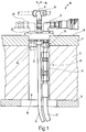
- 10 is a rotary table of a machine tool, not otherwise shown.
- the turntable 10 has a table top 11 and a table housing 12 which is connected to a machine frame 13 in a rotationally fixed manner.
- the table top 11 can be moved back and forth in a manner known per se about an axis of rotation 15 in the direction of a double arrow 16 relative to the machine frame 13.
- Rotary tables of this type serve as workpiece changers, they successively offer workpieces to a spindle of the machine tool, which are clamped on their upper side 17 in receptacles not shown in FIG. 1. Hydraulic oil or compressed air is required to actuate these receptacles, and cooling and flushing oil are also required for flushing and cooling during the machining processes. Furthermore, 17 apparatuses, measuring devices, etc., which are operated fluidically or electrically, can be arranged on the upper side.
- the supply of fluidic and / or electrical energy takes place via a channel 18 arranged centrally in the table top 11 and the table housing 12, which opens into the upper side 17.
- Two lines 21 and 22 run by way of example in this channel in FIG. 2, line 21 being a compressed air line and line 22 being a hydraulic line.
- the two lines come from fixed supply connections for fluids.
- an adapter plate 23 which projects into the channel 18 with a flange.
- connectors 24, 25 and 26 are attached to the adapter plate 23 from below.
- these connecting pieces 24, 25 and 26 are assigned an angle piece 27 for a hydraulic connection, a T-piece 28 for a pneumatic connection and a further angle piece 29 for a hydraulic connection.
- the line 21 is fixed to the connector 24 so that it twists when the table top 11 is rotated.
- the free hanging length of the line 21 running centrally to the axis of rotation 15 is so great that this twisting is possible in the relatively narrow channel 18 without the line 21 being pushed off.
- the connecting piece 24 for the eccentric line 22 comprises a rotary coupling 31 which is screwed onto the adapter plate 23 from below via a screw connection 32.
- the rotary coupling 31 now enables the line 22 to be rotated relative to the screw connection 32.
- the rotary coupling 31 supports the required twisting of the line 22, so that this is possible in the relatively narrow channel 18, although the line 22 is outside the axis of rotation 15 is arranged and itself can be relatively short.
- a corresponding line is also assigned to the connecting piece 26, which line is fastened to the adapter plate 23 via a rotary coupling and a schematically indicated screw connection.
- these components are not shown in FIG. 1.
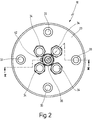
- FIG. 2 shows a top view of an adapter plate 23, which has a slightly different construction than the adapter plate 23 from FIG. 1, but serves the same purpose.
- FIG. 2 it can be seen in FIG. 2 that there are four machine screws 33 in the adapter plate 23, with which the adapter plate 23 is screwed onto the table plate 11. Furthermore, four screw connections 34 can be seen, on which e.g. the elbows 27 and 29 and / or the T-piece 28 can be screwed on. The four screw connections sit in the corners of a square, a further, central screw connection 35 being provided in the center of the square.
- 3 shows a further exemplary embodiment in which the rotary coupling 31 has been completely dispensed with.
- 3 is a section along the line III-III from FIG. 2. For reasons of clarity, only a machine screw 33 and a screw connection 34 and finally the screw connection 35 are shown in FIG. 3.
- connection piece 24 here comprises a cylindrical bolt body 37, to each of which a connection pin 38 or 39 is attached at the top and bottom.
- the bolt body 37 is inserted into a through hole 41 which passes through the adapter plate 23 centrally.
- the bolt body 37 is preferably glued into the through hole 41.
- a pin 42 is provided which runs parallel to the axis of rotation 15 and is seated approximately halfway in the bolt body 37 and in the adapter plate 23.
- a screw connection 43 is screwed onto the lower connecting pin 39, via which the line 21 is firmly connected to the connecting piece 24 and thus to the table top 11.
- the line 22 running outside the axis of rotation 15 is screwed into a threaded bore 45 in the adapter plate 23 by means of a screw connection 44.
- the screw connection 34 is screwed into this threaded bore 45 from above.
- Fig. 3 it can be seen that the lines 21, 22 are arranged in a narrow space in the channel 18. Nevertheless, because of their free-hanging, sufficient length, they can twist in the channel 18 when the table top 11 is rotated relative to the table housing 12.
- the length of the lines here may be greater than in the exemplary embodiment according to FIG. 2.
- the diameter of the adapter plate 23 is so small that the screw connections 43 and 44 are very close to each other. So that it is still possible to mount the lines 21, 22 on the adapter plate 23, the outer lines 22 are first screwed into the threaded bores 45 via the screw connections 44. After the four outer lines 22 are fastened, the central line 21 is first screwed onto the connecting piece 24. Then this is inserted from below into the through hole 41 until the upper connecting pin 38 protrudes sufficiently upwards. Then the bolt body 37, which is now inserted into the through-hole 41, is possibly glued, whereupon a hole is made into which the pin 42 is inserted.
Landscapes
- Engineering & Computer Science (AREA)
- Mechanical Engineering (AREA)
- Machine Tool Units (AREA)
- Auxiliary Devices For Machine Tools (AREA)
Abstract
Description
Die vorliegende Erfindung betrifft eine Werkzeugmaschine mit einem Drehtisch, der eine gegenüber einem Maschinengestell um eine Drehachse verschwenkbare Tischplatte aufweist, auf deren Oberseite von unterhalb der Tischplatte kommende Leitungen führen, die mit raumfesten Versorgungsanschlüssen verbunden sind.The present invention relates to a machine tool with a rotary table which has a table top which can be pivoted about an axis of rotation with respect to a machine frame, on the upper side of which lines coming from below the table top lead and which are connected to fixed supply connections.
Eine derartige Werkzeugmaschine ist aus der DE 83 16 776 U1 bekannt.Such a machine tool is known from DE 83 16 776 U1.
Bei der bekannten Werkzeugmaschine ist ein Anschlußkasten fest auf dem Drehtisch montiert. In einer drehfest mit dem Drehtisch verbundenen Seitenwand des Anschlußkastens sind Steckanschlüsse vorgesehen, während auf der gegenüber dem Drehtisch feststehenden Oberseite des Anschlußkastens eine Drehkupplung angeordnet ist.In the known machine tool, a junction box is firmly mounted on the turntable. Plug connections are provided in a side wall of the connection box, which is connected to the turntable in a manner fixed against relative rotation, while a rotary coupling is arranged on the upper side of the connection box, which is fixed relative to the turntable.
Der die Oberseite bildende Deckel des Anschlußkastens ist mit einem durch den Tisch hindurchgehenden Rohr verbunden, das raumfest ist, also der Drehung des Tisches nicht folgt. In dem Rohr verlaufen Anschlußleitungen von unten nach oben, von denen eine von unten an die Drehkupplung angeschlossen ist. Von der Drehkupplung kann über die Anschlußleitung zugeführtes Fluid über eine weitere Leitung abgenommen werden. Wenn sich der Tisch dreht, bleibt das Oberteil des Anschlußkastens stehen, während sich die Leitung zur Abnahme des Fluids über die Drehkupplung mit dem Tisch mitdreht. Diese Drehung ist laut dieser Druckschrift deshalb möglich, weil die Drehkupplung zentrisch in der Drehachse des Drehtisches liegt.The top of the junction box cover is connected to a tube passing through the table, which is fixed in space, ie does not follow the rotation of the table. Connection lines run from bottom to top in the tube, one of which is connected to the rotary coupling from below. Fluid supplied via the connecting line can be removed from the rotary coupling via a further line. When the table rotates, the upper part of the connection box stops, while the line for removing the fluid rotates with the table via the rotary coupling. According to this publication, this rotation is possible because the rotary coupling lies centrally in the axis of rotation of the rotary table.
Die Steckanschlüsse in der sich mit dem Tisch mitdrehenden Seitenwand des Anschlußkastens sind mit Leitungen verbunden, die im Inneren des Anschlußkastens ggf. in mehrlagigen Schlaufen verlegt sind, so daß sie mit entsprechendem Spiel oder Freiraum das Verdrehen des Drehtisches ermöglichen, wobei sich die Schlaufen ab- oder aufwickeln.The plug connections in the side wall of the connection box which rotates with the table are connected to lines which may be laid in multilayer loops in the interior of the connection box, so that they allow the turntable to be rotated with appropriate play or free space, the loops becoming detached. or wind up.
Ein derartiger Drehtisch wird bei Werkzeugmaschinen eingesetzt, bei denen auf der Oberseite des Drehtisches zumindest zwei Werkstücke angeordnet sind, die durch Verdrehen der Tischplatte nacheinander einer Spindel zur Bearbeitung angeboten werden. Die Leitungen führen Bohr- und Spülöl, Hydrauliköl oder Druckluft auf die Oberseite des Drehtisches, um dort zur Betätigung einer Werkstückaufnahme, zum Spülen während der Werkstückbearbeitung etc. verwendet zu werden. Diese Fluide werden an raumfesten Versorgungsanschlüssen bereitgestellt, die über die Leitungen mit der Oberseite der sich drehenden Tischplatte verbunden werden.Such a turntable is used in machine tools in which at least two workpieces are arranged on the top of the turntable and are offered for machining by turning the table top one after the other. The lines lead drilling and flushing oil, hydraulic oil or compressed air to the top of the turntable, in order to actuate a workpiece holder, for flushing during workpiece machining etc. to be used. These fluids are provided at fixed supply connections, which are connected via the lines to the top of the rotating table top.
Bei der bekannten Werkzeugmaschine ist eine zentrisch zu der Drehachse der Tischplatte verlaufende Leitung mit der Drehkupplung verbunden, während die außerhalb der Drehachse verlaufenden Leitungen auf der Tischplatte innerhalb des Anschlußkastens in Schlaufen gelegt sind. Auf diese Weise können sowohl in der Drehachse als auch außerhalb der Drehachse Leitungen auf die Oberseite der Tischplatte führen und dort die benötigten Fluide bereitstellen.In the known machine tool, a line running centrally to the axis of rotation of the table top is connected to the rotary coupling, while the lines running outside the axis of rotation are placed in loops on the table top within the connection box. In this way, lines can lead to the top of the table top both in the axis of rotation and outside of the axis of rotation and provide the required fluids there.
In der Praxis hat sich gezeigt, daß der Anschlußkasten bei der bekannten Werkzeugmaschine insofern von Nachteil ist, als er auf dem Werkstücktisch relativ viel Platz erfordert, so daß der Raum zum Aufspannen der Werkstücke durch den Anschlußkasten merklich verringert wird. Nun ist es aber ein Bestreben bei der Konstruktion derartige Werkzeugmaschinen, diese mit möglichst geringen Außenabmaßen auszulegen, so daß der Platz auch auf der Tischplatte des Drehtisches möglichst gut ausgenutzt werden soll. Diesen Anforderungen wird die bekannte Werkzeugmaschine nicht gerecht.In practice, it has been shown that the connection box in the known machine tool is disadvantageous in that it requires a relatively large amount of space on the workpiece table, so that the space for clamping the workpieces is markedly reduced by the connection box. Now, however, when designing such machine tools, it is endeavored to design them with the smallest possible external dimensions, so that the space on the table top of the turntable is to be used as well as possible. The known machine tool does not meet these requirements.
Ein weiterer Nachteil bei der bekannten Werkzeugmaschine besteht darin, daß die aus Anschlußkasten und Rohr bestehende Mechanik relativ aufwendig und damit sehr kostenintensiv ist.Another disadvantage of the known machine tool is that the mechanics consisting of connection box and tube are relatively complex and therefore very cost-intensive.
Nun ist es aus der DE 36 20 086 C2 bereits bekannt, das oben erwähnte Platzproblem dadurch zu lösen, daß die Leitungen oberhalb des Werkstücktisches an einem Punkt in der Nähe der Drehachse an einem raumfesten Punkt der Werkzeugmaschine angeschlossen und lose nach unten hängend mit einem Anschlußkasten auf dem Werkstücktisch verbunden sind.It is already known from DE 36 20 086 C2 to solve the space problem mentioned above in that the lines above the workpiece table at a point near the axis of rotation at a fixed point on the machine tool connected and loosely connected to a junction box on the workpiece table.
Da die Leitungen oben in der Nähe der Drehachse der Tischplatte angeschlossen sind, ergibt sich eine symmetrische und die Leitungen nur minimal mechanisch verformende Bewegung, wenn der Werkstücktisch jeweils um 180° hin- und hergedreht wird.Since the cables are connected at the top near the axis of rotation of the table top, there is a symmetrical and only minimal mechanical deformation of the cables when the workpiece table is rotated back and forth by 180 °.
Bei diesen frei herabhängenden Leitungen ist jedoch von Nachteil, daß sie zum einen mechanisch beschädigt werden können und zum anderen ständig dem Einfluß von Kühl- und Spülmitteln ausgesetzt sind, die einen aggressiven Einfluß auf die Kunststoff- und Gummiisolierungen der Leitungen ausüben. Darüber hinaus stören die herabhängenden Leitungen, wenn Bedienungspersonal im Bereich des Drehtisches Montage- oder Wartungsarbeiten durchführen muß.A disadvantage of these freely hanging lines is that they can be mechanically damaged on the one hand and on the other hand are constantly exposed to the influence of coolants and flushing agents which exert an aggressive influence on the plastic and rubber insulation of the lines. In addition, the hanging cables interfere when operating personnel have to carry out assembly or maintenance work in the area of the turntable.
Hiervon ausgehend ist es Aufgabe der vorliegenden Erfindung, die eingangs genannte Werkzeugmaschine derart weiterzubilden, daß bei einfachem konstruktivem Aufwand der Anschluß auch mehrerer Leitungen an die sich drehende Tischplatte möglich ist, wobei der Platzbedarf auf der Oberseite der Tischplatte möglichst gering sein soll.Proceeding from this, it is an object of the present invention to further develop the machine tool mentioned at the outset in such a way that, with a simple structural outlay, it is also possible to connect a plurality of lines to the rotating table top, the space requirement on the top of the table top being as small as possible.
Bei der eingangs genannten Werkzeugmaschine wird diese Aufgabe erfindungsgemäß dadurch gelöst, daß die Leitungen über nach unten weisende Anschlußstücke, die mit der Tischplatte in deren mittleren Bereich drehfest verbunden sind, von unten derart an der Tischplatte befestigt sind, daß sie frei nach unten hängen.In the machine tool mentioned in the introduction, this object is achieved according to the invention in that the lines are attached to the table top from below in such a way that they hang freely downward via connecting pieces which are connected in a rotationally fixed manner to the table top in the central region thereof.
Die der Erfindung zugrundeliegende Aufgabe wird auf diese Weise vollkommen gelöst.The object underlying the invention is completely achieved in this way.
Die mehreren Leitungen können jetzt in der Mitte der Tischplatte und an deren Unterseite nebeneinander herunterhängen, wobei sie durch die Tischplatte hindurch mit deren Oberseite verbunden sind. Auf der Oberseite der Tischplatte ist kein gesonderter Anschlußkasten mehr erforderlich, die Funktion des Anschlußkastens übernimmt sozusagen die Tischplatte selbst, so daß der für aufzuspannende Werkstücke zur Verfügung stehende Platz auf der Oberseite der Tischplatte gegenüber den bekannten Werkzeugmaschinen deutlich vergrößert wurde. Bei der neuen Werkzeugmaschine ist aber auch ein geringer konstruktiver Aufwand erforderlich, um die Verbindung zwischen den Leitungen und der Tischplatte herzustellen. Es müssen lediglich unten an der Tischplatte Anschlußstücke befestigt werden, an denen wiederum dann die Leitungen montiert werden.The multiple lines can now hang in the middle of the table top and on the underside next to each other, being connected through the table top to the top. On the top of the table top, a separate connection box is no longer required, the function of the connection box takes over the table top itself, so to speak, so that the space available for workpieces to be clamped on the top of the table top has been significantly increased compared to the known machine tools. With the new machine tool, however, less design effort is required to establish the connection between the lines and the table top. It only has to be attached to the table top at the bottom, on which in turn the cables are then mounted.
Dabei ist es bevorzugt, wenn zumindest eine der Leitungen eine derartige frei hängende Länge aufweist, die beim Hin- und Herdrehen der Tischplatte ein Verwinden der Leitung zuläßt.It is preferred if at least one of the lines has such a free-hanging length that allows the line to be twisted when the table top is turned back and forth.
Hier ist von Vorteil, daß die Anschlußstücke einfache Verschraubungen sein können, mit denen die Leitungen unmittelbar fest von unten an die Tischplatte angeschraubt werden. Die Erfinder der vorliegenden Anmeldung haben nämlich erkannt, daß auch mehrere auf engem Raum nebeneinander hängende Leitungen ein Hin- und Herdrehen der Tischplatte um 180° dann ermöglichen, wenn sie über eine entsprechende Länge frei herunterhängen, so daß ein Verwinden der Leitungen möglich ist. Bisher war angenommen worden, daß ein derartiges Verwinden der Leitungen nur möglich ist, wenn diese von oben frei auf die Tischplatte herunterhängen, so daß sie oberhalb der Tischplatte genügend Platz haben, um sich umeinander zu drehen, wie dies aus der eingangs genannten DE 36 20 086 C2 bekannt ist.The advantage here is that the connectors can be simple screw connections with which the lines are screwed directly to the table top from below. The inventors of the present application have recognized that even several lines hanging side by side in a narrow space enable the table top to be turned back and forth by 180 ° if they hang down freely over a corresponding length, so that the lines can be twisted. So far it was assumed that such a twisting of the lines is only possible if they hang freely from above on the table top, so that they have enough space above the table top to rotate around one another, as is described in DE 36 20 086 C2 is known.
Andererseits ist es bevorzugt, wenn zumindest ein Anschlußstück eine Drehkupplung umfaßt.On the other hand, it is preferred if at least one connecting piece comprises a rotary coupling.
Hier ist von Vorteil, daß insbesondere bei außermittig angeordneten Leitungen deren Verwinden dadurch erleichtert wird, daß die Leitung von unten über eine Drehkupplung an der Tischplatte befestigt ist. Die Erfinder der vorliegenden Anmeldung haben hier erkannt, daß derartige Drehkupplungen auch unterhalb der Tischplatte und außerhalb der Drehachse in vorteilhafter Weise angeordnet werden können, um auf geringem Raum mehrere Leitungen nebeneinander von unten durch die Tischplatte auf deren Oberseite zu führen. Ein weiterer Vorteil liegt hier darin, daß die Leitungen kürzer sein können, als dies bei frei hängenden Leitungen der Fall ist.The advantage here is that twisting is facilitated in particular in the case of eccentrically arranged lines in that the line is fastened to the table top from below via a rotary coupling. The inventors of the present application have recognized here that such rotary couplings can also be arranged below the table top and outside the axis of rotation in an advantageous manner in order to run a plurality of lines side by side from below through the table top on its upper side. Another advantage here is that the lines can be shorter than is the case with freely hanging lines.
Aus der eingangs genannten DE 83 16 776 U1 war bisher nur bekannt, derartige Drehkupplungen in der Drehachse des Drehtisches anzuordnen und sie dazu auf einem sich nicht mit der Tischplatte drehenden Deckelteil des Anschlußkastens zu montieren. Zur Erleichterung der Verwindung der Leitungen war die Drehkupplung bei der bekannten Konstruktion nicht vorgesehen.From the aforementioned DE 83 16 776 U1 it was previously only known to arrange such rotary couplings in the axis of rotation of the turntable and to mount them for this purpose on a cover part of the connection box which does not rotate with the table top. To facilitate the twisting of the lines, the rotary coupling was not provided in the known construction.
Weiter ist es bevorzugt, wenn eine erste Leitung etwa zentrisch zu der Drehachse verläuft und weitere Leitungen vorzugsweise symmetrisch zu der ersten Leitung angeordnet sind.It is further preferred if a first line runs approximately centrally to the axis of rotation and further lines are preferably arranged symmetrically to the first line.
Bei dieser Konstruktion kann z.B. die erste Leitung über eine Schraubverbindung mit der Tischplatte verbunden sein, während die weiteren Leitungen über Drehkupplungen an der Unterseite der Tischplatte montiert sind. Wegen der symmetrischen Anordnung ist hier nur sehr wenig Platz erforderlich, auf die Oberseite der Tischplatte münden so z.B. vier Anschlußzapfen, die in den Ecken eines Quadrates angeordnet sind, während mittig in dem Quadrat ein weiterer Anschlußzapfen hochsteht.In this construction, for example, the first line can be connected to the table top via a screw connection, while the further lines are mounted on the underside of the table top via rotary couplings. Because of the symmetrical arrangement, very little space is required here, for example, four connecting pins, which are arranged in the corners of a square, open onto the top of the table top, while another connecting pin stands up in the center of the square.
Insgesamt ist es bevorzugt, wenn die Anschlußstücke an einem Adapterteller befestigt sind, der von oben auf einen in der Oberseite der Tischplatte mündenden, zentralen Kanal aufgesetzt ist, in den die Anschlußstücke hineinragen.Overall, it is preferred if the connecting pieces are fastened to an adapter plate which is placed from above onto a central channel opening into the upper side of the table top and into which the connecting pieces protrude.
Diese Maßnahme ist konstruktiv von Vorteil, die Anschlußstücke können an dem Adapterteller zusammen mit den Leitungen vormontiert werden, die dann nur noch von oben in den Kanal "eingefädelt" werden müssen. Der Durchmesser des Kanales muß lediglich so groß sein, daß sämtliche Anschlußstücke in ihn eingeführt werden können, im Inneren des Kanales selber sind keine Montagearbeiten erforderlich. Bei dieser Konstruktion ist auch eine leichte Wartung möglich, der Adapterteller muß lediglich abgeschraubt und soweit hochgezogen werden, daß auf die Anschlußstücke zugegriffen werden kann, um z.B. eine defekte Leitung auszutauschen.This measure is structurally advantageous, the connecting pieces can be pre-assembled on the adapter plate together with the lines, which then only have to be "threaded" into the channel from above. The diameter of the channel only has to be large enough that all the connecting pieces can be inserted into it. No assembly work is required inside the channel itself. With this construction, easy maintenance is also possible, the adapter plate only has to be unscrewed and pulled up to the extent that the connecting pieces can be accessed, e.g. replace a defective line.
In einer Weiterbildung ist es hier bevorzugt, wenn der Adapterteller eine zentrische Durchgangsbohrung aufweist, in die für eine zentrisch zu der Drehachse verlaufende Leitung ein Anschlußstück eingefügt ist, das einen fest in der Durchgangsbohrung sitzenden, zylindrischen Bolzenkörper mit endseitigen Anschlußzapfen aufweist.In a further development, it is preferred here if the adapter plate has a central through-hole, into which a connection piece is inserted for a line running centrally to the axis of rotation, which has a cylindrical bolt body with a terminal pin that is firmly seated in the through-hole.
Auch diese Maßnahme ist im Hinblick auf geringen Platzbedarf von Vorteil, nach der Befestigung der Leitung an einem der endseitigen Anschlußzapfen muß lediglich noch der Bolzenkörper von unten in die Durchgangsbohrung eingefügt werden. Der Platzbedarf dieser Verbindung ist sehr gering, da keine Verschraubung am Adapterteller verwendet wird. Es ist jetzt z.B. möglich, vier außerhalb der Drehachse verlaufende Leitungen über Verschraubungen an dem Adapterteller zu befestigen und in der Mitte lediglich so viel Platz auszusparen, daß die Durchgangsbohrung frei bleibt. Nachdem die äußeren Leitungen montiert wurden, muß lediglich noch der Bolzenkörper mit daran befestigter zentrischer Leitung von unten eingeschoben werden. Insgesamt führt diese Konstruktion also auch dazu, daß ein Adapterteller mit sehr geringem Außendurchmesser verwendet werden kann, so daß insgesamt der Platzbedarf auf der Oberseite der Tischplatte sehr gering ist.This measure is also advantageous in view of the small space requirement; after the line has been fastened to one of the end connection pins, only the bolt body has to be inserted into the through hole from below. The space required for this connection is very small since no screw connection is used on the adapter plate. It is now possible, for example, to fasten four lines running outside the axis of rotation via screw connections on the adapter plate and only save enough space in the middle so that the Through hole remains free. After the outer cables have been installed, the bolt body with the central cable attached to it only has to be inserted from below. Overall, this construction also means that an adapter plate with a very small outside diameter can be used, so that the overall space requirement on the top of the table top is very small.
In einer Weiterbildung ist es dann bevorzugt, wenn die Anschlußstücke der weiteren Leitungen Drehkupplungen umfassen, die von unten über eine Schraubverbindung an dem Adapterteller befestigt sind.In a further development, it is preferred if the connecting pieces of the further lines comprise rotary couplings which are fastened to the adapter plate from below via a screw connection.
Die Drehkupplungen weisen den oben bereits erwähnten Vorteil auf, daß für die Leitungen insgesamt nur sehr wenig Platz erforderlich ist, um ihnen das Verwinden bei dem Hin- und Herdrehen der Tischplatte um 180° zu ermöglichen. Insbesondere im Zusammenhang mit dem zuvor erwähnten Bolzenkörper läßt sich so auf sehr geringem Platz ein Anschluß von z.B. fünf Leitungen an die Tischplatte ermöglichen.The rotary couplings have the advantage already mentioned above that very little space is required overall for the lines in order to enable them to be twisted when the table top is turned back and forth by 180 °. Especially in connection with the aforementioned bolt body, a connection of e.g. allow five lines to the table top.
In einer Weiterbildung ist es dann bevorzugt, wenn der Bolzen mit dem Adapterteller verstiftet ist.In a further development, it is preferred if the bolt is pinned to the adapter plate.
Hier ist von Vorteil, daß nach dem Einfügen des Bolzens durch die Verstiftung dafür gesorgt wird, daß dieser sich gegenüber der Tischplatte nicht verdrehen kann. Dies wird auf konstruktiv denkbar einfache Weise durch eine Verstiftung ermöglicht.The advantage here is that after the pin has been inserted, the pin ensures that it cannot twist relative to the table top. This is made possible by a pinning in a structurally very simple manner.
Ferner ist es bevorzugt, wenn parallel zu der Drehachse von oben ein Stift in den Adapterteller eingeschoben ist, der etwa je zur Hälfte in dem Bolzenkörper und dem Adapterteller sitzt.It is further preferred if, parallel to the axis of rotation, a pin is inserted into the adapter plate from above, approximately half of which is seated in the bolt body and the adapter plate.
Hier ist von Vorteil, daß es sich um eine konstruktiv sehr einfache Verstiftung handelt, das den Stift aufnehmende Loch, das etwa je zur Hälfte in dem Bolzenkörper und in dem Adapterteller sitzt, kann nach dem Einfügen des Bolzenkörpers gebohrt werden, so daß sich die Montage insgesamt sehr vereinfacht. Beim Einfügen des Bolzenkörpers muß nämlich nicht bereits darauf geachtet werden, daß die beiden Hälften der für den Stift vorgesehenen Bohrungen miteinander fluchten. Diese Maßnahme hat auch Vorteile gegenüber einem Stift, der quer zu der Drehachse eingeschoben wird, weil auch bei einer derartigen Konstruktion schon beim Einfügen des Bolzenkörpers darauf geachtet werden müßte, daß die für den Stift vorgesehenen Löcher in Bolzenkörper und Tischplatte miteinander fluchten.The advantage here is that it is a structurally very simple pinning, the hole receiving the pin, which sits about half each in the bolt body and in the adapter plate, can be drilled after inserting the bolt body, so that the assembly overall very simplified. When inserting the bolt body, it is not necessary to ensure that the two halves of the holes provided for the pin are aligned. This measure also has advantages over a pin that is inserted transversely to the axis of rotation, because even with such a construction, care should be taken when inserting the bolt body that the holes provided for the pin in the bolt body and table top are aligned.
Darüber hinaus ist es bevorzugt, wenn der Bolzenkörper in die Durchgangsbohrung eingeklebt ist.In addition, it is preferred if the bolt body is glued into the through hole.
Bei dieser Maßnahme ist von Vorteil, daß der Bolzenkörper auf einfache Weise axial unverschieblich gehalten werden kann.This measure has the advantage that the bolt body can be kept axially immovable in a simple manner.
Weitere Vorteile ergeben sich aus der Beschreibung und der beigefügten Zeichnung.Further advantages result from the description and the attached drawing.
Es versteht sich, daß die vorstehend genannten und die nachstehend noch zu erläuternden Merkmale nicht nur in den jeweils angegebenen Kombinationen, sondern auch in anderen Kombinationen oder in Alleinstellung verwendbar sind, ohne den Rahmen der vorliegenden Erfindung zu verlassen.It goes without saying that the features mentioned above and those yet to be explained below can be used not only in the respectively specified combinations but also in other combinations or on their own without departing from the scope of the present invention.
Ausführungsbeispiele der Erfindung sind in der beigefügten Zeichnung dargestellt und werden in der nachfolgenden Beschreibung näher erläutert. Es zeigen:
- Fig. 1
- einen Längsschnitt durch einen Drehtisch der neuen Werkzeugmaschine;
- Fig. 2
- eine Draufsicht auf einen Adapterteller, wie er bei dem Drehtisch aus Fig. 1 verwendet werden kann; und
- Fig. 3
- einen Querschnitt längs der Linie III-III aus Fig. 2 durch ein weiteren Ausführungsbeispiel des Drehtisches der neuen Werkzeugmaschine.
- Fig. 1
- a longitudinal section through a turntable of the new machine tool;
- Fig. 2
- a plan view of an adapter plate, as it can be used in the rotary table of FIG. 1; and
- Fig. 3
- a cross section along the line III-III of Fig. 2 by a further embodiment of the turntable of the new machine tool.
In Fig. 1 ist mit 10 ein Drehtisch einer ansonsten nicht dargestellten Werkzeugmaschine gezeigt. Der Drehtisch 10 weist eine Tischplatte 11 sowie ein Tischgehäuse 12 auf, das drehfest mit einem Maschinengestell 13 verbunden ist. Die Tischplatte 11 ist in an sich bekannter Weise um eine Drehachse 15 in Richtung eines Doppelpfeiles 16 gegenüber dem Maschinengestell 13 hin- und herbewegbar.In Fig. 1, 10 is a rotary table of a machine tool, not otherwise shown. The
Derartige Drehtische dienen als Werkstückwechsler, sie bieten einer Spindel der Werkzeugmaschine nacheinander Werkstücke an, die auf ihrer Oberseite 17 in in Fig. 1 nicht dargestellten Aufnahmen eingespannt sind. Zur Betätigung dieser Aufnahmen wird Hydrauliköl oder Druckluft benötigt, wobei zum Spülen und Kühlen während der Bearbeitungsvorgänge weiter Kühl- und Spülöl benötigt wird. Ferner können auf der Oberseite 17 Teilapparate, Meßgeräte etc. angeordnet sein, die fluidisch oder elektrisch betrieben werden.Rotary tables of this type serve as workpiece changers, they successively offer workpieces to a spindle of the machine tool, which are clamped on their
Die Versorgung mit fluidischer und/oder elektrischer Energie erfolgt über einen zentrisch in der Tischplatte 11 sowie dem Tischgehäuse 12 angeordneten Kanal 18, der in der Oberseite 17 mündet. In diesem Kanal verlaufen in Fig. 2 beispielhaft zwei Leitungen 21 und 22, wobei die Leitung 21 eine Druckluftleitung und die Leitung 22 eine Hydraulikleitung ist. Die beiden Leitungen kommen von raumfesten Versorgungsanschlüssen für Fluide.The supply of fluidic and / or electrical energy takes place via a
Oben auf dem Kanal 18 sitzt ein Adapterteller 23, der mit einem Flansch in den Kanal 18 hineinragt. In Fig. 1 sind von unten Anschlußstücke 24, 25 und 26 an dem Adapterteller 23 befestigt. Diesen Anschlußstücken 24, 25 und 26 sind auf der Oberseite 17 ein Winkelstück 27 für einen Hydraulikanschluß, ein T-Stück 28 für einen Pneumatik-Anschluß sowie ein weiteres Winkelstück 29 für einen Hydraulik-Anschluß zugeordnet.At the top of the
Die Leitung 21 ist fest mit dem Anschlußstück 24 verbunden, so daß sie sich beim Drehen der Tischplatte 11 verwindet. Die frei hängende Länge der zentrisch zu der Drehachse 15 verlaufenden Leitung 21 ist so groß, daß dieses Verwinden in dem relativ engen Kanal 18 möglich ist, ohne daß die Leitung 21 abgedrückt wird.The
Im Gegensatz dazu umfaßt das Anschlußstück 24 für die außermittig verlaufende Leitung 22 eine Drehkupplung 31, die über eine Schraubverbindung 32 von unten an den Adapterteller 23 angeschraubt ist. Die Drehkupplung 31 ermöglicht jetzt ein Verdrehen der Leitung 22 gegenüber der Schraubverbindung 32. Beim Drehen der Tischplatte 11 unterstützt die Drehkupplung 31 die erforderliche Verwindung der Leitung 22, so daß dies in dem relativ engen Kanal 18 möglich ist, obwohl die Leitung 22 außerhalb der Drehachse 15 angeordnet ist und selbst relativ kurz sein kann.In contrast to this, the connecting
Selbstverständlich ist auch dem Anschlußstück 26 eine entsprechende Leitung zugeordnet, die über eine Drehkupplung und eine schematisch angedeutete Schraubverbindung an dem Adapterteller 23 befestigt ist. Aus Gründen der Übersichtlichkeit sind diese Bauteile jedoch in Fig. 1 nicht dargestellt.Of course, a corresponding line is also assigned to the connecting
Fig. 2 zeigt eine Draufsicht auf eine Adapterplatte 23, die eine geringfügig andere Konstruktion aufweist als die Adapterplatte 23 aus Fig. 1, aber demselben Zweck dient.FIG. 2 shows a top view of an
Zunächst ist in Fig. 2 zu erkennen, daß in der Adapterplatte 23 vier Maschinenschrauben 33 sitzen, mit denen die Adapterplatte 23 an die Tischplatte 11 angeschraubt ist. Ferner sind vier Schraubanschlüsse 34 zu erkennen, auf die z.B. die Winkelstücke 27 und 29 und/oder das T-Stück 28 aufgeschraubt werden können. Die vier Schraubanschlüsse sitzen in den Ecken eines Quadrates, wobei in der Mitte des Quadrates ein weiterer, mittiger Schraubanschluß 35 vorgesehen ist.First of all, it can be seen in FIG. 2 that there are four
Auf diese Weise ist es möglich, insgesamt fünf Leitungen in dem Kanal 18 zu führen, wobei ein Verdrehen der Tischplatte (um 180° hin und her) 11 dazu führt, daß sich die an den Schraubanschluß 35 angeschlossene Leitung 21 in sich verwindet, während sich die an die äußeren Schraubanschlüsse 34 von unten angeschlossenen Leitungen, wie z.B. die Leitung 22, über die Drehkupplung 31 verdrehen und verwinden können.In this way, it is possible to run a total of five lines in the
In Fig. 3 ist jedoch ein weiteres Ausführungsbeispiel gezeigt, bei dem auf die Drehkupplung 31 ganz verzichtet wurde. Fig. 3 ist ein Schnitt längs der Linie III-III aus Fig. 2. Aus Gründen der Übersichtlichkeit ist in Fig. 3 lediglich eine Maschinenschraube 33 sowie ein Schraubanschluß 34 und schließlich der Schraubanschluß 35 gezeigt.3 shows a further exemplary embodiment in which the
Abweichend von der Konstruktion aus Fig. 1 umfaßt das Anschlußstück 24 hier einen zylindrischen Bolzenkörper 37, an den oben und unten jeweils ein Anschlußzapfen 38 bzw. 39 angefügt ist. Der Bolzenkörper 37 ist in eine Durchgangsbohrung 41 eingefügt, die den Adapterteller 23 zentrisch durchsetzt. Der Bolzenkörper 37 ist vorzugsweise in die Durchgangsbohrung 41 eingeklebt.1, the
Zur Unterstützung der Verbindung zwischen Bolzenkörper 37 und Adapterplatte 23 ist ein Stift 42 vorgesehen, der parallel zur Drehachse 15 verläuft und etwa je zur Hälfte in dem Bolzenkörper 37 sowie in dem Adapterteller 23 sitzt.To support the connection between the
Auf den unteren Anschlußzapfen 39 ist eine Schraubverbindung 43 aufgeschraubt, über die die Leitung 21 fest mit dem Anschlußstück 24 und damit der Tischplatte 11 verbunden ist.A
Die außerhalb der Drehachse 15 verlaufende Leitung 22 ist mittels einer Schraubverbindung 44 in eine Gewindebohrung 45 in dem Adapterteller 23 eingeschraubt. Von oben ist in diese Gewindebohrung 45 der Schraubanschluß 34 eingeschraubt.The
In Fig. 3 ist zu erkennen, daß die Leitungen 21, 22 auf engstem Raum in dem Kanal 18 angeordnet sind. Dennoch können sie sich wegen ihrer frei hängenden, ausreichenden Länge in dem Kanal 18 verwinden, wenn die Tischplatte 11 gegenüber dem Tischgehäuse 12 verdreht wird. Die Länge der Leitungen ist hier ggf. größer als bei dem Ausführungsbeispiel gemäß Fig. 2.In Fig. 3 it can be seen that the
Der Durchmesser der Adapterplatte 23 ist so gering, daß die Schraubverbindungen 43 und 44 sehr dicht nebeneinander liegen. Damit jetzt überhaupt noch eine Montage der Leitungen 21, 22 an der Adapterplatte 23 möglich ist, werden zunächst die äußeren Leitungen 22 über die Schraubverbindungen 44 in die Gewindebohrungen 45 eingeschraubt. Nachdem die vier äußeren Leitungen 22 befestigt sind, wird die zentrische Leitung 21 zunächst an das Anschlußstück 24 angeschraubt. Daraufhin wird dieses von unten in die Durchgangsbohrung 41 eingeschoben, bis der obere Anschlußzapfen 38 nach oben ausreichend vorsteht. Dann wird der nun in die Durchgangsbohrung 41 eingefügte Bolzenkörper 37 ggf. verklebt, woraufhin eine Bohrung gesetzt wird, in die der Stift 42 eingeschoben wird. Auf diese konstruktiv sehr einfache Weise können insgesamt fünf Leitungen 21, 22 auf engstem Raum von unten an dem Adapterteller 23 befestigt werden. Diese Leitungen werden nun von oben in den Kanal 18 eingefädelt und dieser dann durch die Adapterplatte 23 verschlossen. Daraufhin wird die Adapterplatte 23 über die Maschinenschrauben 33 fest an die Tischplatte 11 angeschraubt.The diameter of the
Soll eine der Leitungen 21, 22 ausgewechselt werden, so müssen lediglich die Maschinenschrauben 33 gelöst werden, damit die Adapterplatte 23 mit den daran hängenden Leitungen 21, 22 nach oben hochgezogen werden kann, so daß die Schraubverbindungen 43, 44 zugängig sind.If one of the
Claims (10)
dadurch gekennzeichnet, daß die Leitungen (21, 22) über nach unten weisende Anschlußstücke (24, 25, 26), die mit der Tischplatte (11) in deren mittlerem Bereich drehfest verbunden sind, von unten derart an der Tischplatte (11) befestigt sind, daß sie frei nach unten hängen.Machine tool with a turntable (10) which has a table top (11) which can be pivoted about an axis of rotation (15) relative to a machine frame (13), on the top (17) of which lines (21, 22) coming from below the table top (11) lead which are connected to fixed supply connections,
characterized in that the lines (21, 22) are fastened to the table top (11) from below via downward-facing connecting pieces (24, 25, 26) which are connected in a rotationally fixed manner to the table top (11) in the central region thereof that they hang freely down.
Applications Claiming Priority (2)
| Application Number | Priority Date | Filing Date | Title |
|---|---|---|---|
| DE19615425A DE19615425C2 (en) | 1996-04-19 | 1996-04-19 | Machine tool with a turntable |
| DE19615425 | 1996-04-19 |
Publications (2)
| Publication Number | Publication Date |
|---|---|
| EP0802016A1 true EP0802016A1 (en) | 1997-10-22 |
| EP0802016B1 EP0802016B1 (en) | 2000-04-05 |
Family
ID=7791698
Family Applications (1)
| Application Number | Title | Priority Date | Filing Date |
|---|---|---|---|
| EP97101077A Expired - Lifetime EP0802016B1 (en) | 1996-04-19 | 1997-01-24 | Machine tool with rotating table |
Country Status (5)
| Country | Link |
|---|---|
| US (1) | US5878633A (en) |
| EP (1) | EP0802016B1 (en) |
| JP (1) | JP3394882B2 (en) |
| DE (2) | DE19615425C2 (en) |
| ES (1) | ES2145522T3 (en) |
Cited By (1)
| Publication number | Priority date | Publication date | Assignee | Title |
|---|---|---|---|---|
| WO2018019668A3 (en) * | 2016-07-26 | 2018-04-26 | Fresenius Medical Care Deutschland Gmbh | Rotary union for a conveyor system and conveyor system with a rotary union, as well as method for conveying objects from workstation to workstation |
Families Citing this family (2)
| Publication number | Priority date | Publication date | Assignee | Title |
|---|---|---|---|---|
| DE19835954A1 (en) * | 1998-08-08 | 2000-02-17 | Index Werke Kg Hahn & Tessky | Machine tool |
| JP6203788B2 (en) | 2015-07-23 | 2017-09-27 | ファナック株式会社 | Rotary table device and electric discharge machine equipped with the rotary table device |
Citations (6)
| Publication number | Priority date | Publication date | Assignee | Title |
|---|---|---|---|---|
| US2911767A (en) * | 1958-01-24 | 1959-11-10 | Sielemann Hans | Grinding machine |
| US3170375A (en) * | 1962-08-03 | 1965-02-23 | Samuel Briskman | Machine tool for milling pinking shear blades |
| DE8316776U1 (en) | 1983-06-09 | 1983-11-03 | Chiron Werke GmbH, 7200 Tuttlingen | Machine tool table |
| DE3620086C2 (en) | 1986-06-14 | 1988-05-19 | Chiron-Werke Gmbh, 7200 Tuttlingen, De | |
| DE4038660A1 (en) * | 1990-12-04 | 1992-06-11 | Wanderer Maschinen Gmbh | Pipe-coupling mechanism on machine tool - can move vertically below centre of gravity of pallet |
| EP0564842A1 (en) * | 1992-04-04 | 1993-10-13 | Chiron-Werke GmbH & Co. KG | Machine tool with turntable |
Family Cites Families (3)
| Publication number | Priority date | Publication date | Assignee | Title |
|---|---|---|---|---|
| FR2243757B1 (en) * | 1973-09-15 | 1978-11-24 | Sauter Kg Feinmechanik | |
| US4380939A (en) * | 1980-07-01 | 1983-04-26 | Cameron Iron Works, Inc. | Rotary indexing table |
| DE3025638C2 (en) * | 1980-07-07 | 1982-08-12 | Fa. Gottlieb Gühring, 7470 Ebingen | Rotary indexing table machine |
-
1996
- 1996-04-19 DE DE19615425A patent/DE19615425C2/en not_active Expired - Fee Related
-
1997
- 1997-01-24 ES ES97101077T patent/ES2145522T3/en not_active Expired - Lifetime
- 1997-01-24 EP EP97101077A patent/EP0802016B1/en not_active Expired - Lifetime
- 1997-01-24 DE DE59701386T patent/DE59701386D1/en not_active Expired - Lifetime
- 1997-02-18 JP JP04856997A patent/JP3394882B2/en not_active Expired - Fee Related
- 1997-04-04 US US08/832,765 patent/US5878633A/en not_active Expired - Lifetime
Patent Citations (6)
| Publication number | Priority date | Publication date | Assignee | Title |
|---|---|---|---|---|
| US2911767A (en) * | 1958-01-24 | 1959-11-10 | Sielemann Hans | Grinding machine |
| US3170375A (en) * | 1962-08-03 | 1965-02-23 | Samuel Briskman | Machine tool for milling pinking shear blades |
| DE8316776U1 (en) | 1983-06-09 | 1983-11-03 | Chiron Werke GmbH, 7200 Tuttlingen | Machine tool table |
| DE3620086C2 (en) | 1986-06-14 | 1988-05-19 | Chiron-Werke Gmbh, 7200 Tuttlingen, De | |
| DE4038660A1 (en) * | 1990-12-04 | 1992-06-11 | Wanderer Maschinen Gmbh | Pipe-coupling mechanism on machine tool - can move vertically below centre of gravity of pallet |
| EP0564842A1 (en) * | 1992-04-04 | 1993-10-13 | Chiron-Werke GmbH & Co. KG | Machine tool with turntable |
Non-Patent Citations (1)
| Title |
|---|
| J. FEULNER: "Druckölversorgung hydraulischer Spannelemente auf schwenk- und drehbaren EInrichtungen", WERKSTATTSTECHNIK, ZEITSCHRIFT FUR INDUSTRIELLE FERTIGUNG, vol. 68, no. 2, February 1978 (1978-02-01), BERLIN DE, pages 73 - 75, XP002034060 * |
Cited By (2)
| Publication number | Priority date | Publication date | Assignee | Title |
|---|---|---|---|---|
| WO2018019668A3 (en) * | 2016-07-26 | 2018-04-26 | Fresenius Medical Care Deutschland Gmbh | Rotary union for a conveyor system and conveyor system with a rotary union, as well as method for conveying objects from workstation to workstation |
| US10745214B2 (en) | 2016-07-26 | 2020-08-18 | Fresenius Medical Care Deutschland Gmbh | Rotary union for a conveyor system and conveyor system with a rotary union, as well as method for conveying objects from workstation to workstation |
Also Published As
| Publication number | Publication date |
|---|---|
| EP0802016B1 (en) | 2000-04-05 |
| DE59701386D1 (en) | 2000-05-11 |
| US5878633A (en) | 1999-03-09 |
| JP3394882B2 (en) | 2003-04-07 |
| JPH09290336A (en) | 1997-11-11 |
| DE19615425C2 (en) | 1998-09-10 |
| DE19615425A1 (en) | 1997-10-23 |
| ES2145522T3 (en) | 2000-07-01 |
Similar Documents
| Publication | Publication Date | Title |
|---|---|---|
| DE1214512B (en) | Expanding mandrel for centering tubular workpieces of different diameters | |
| WO2000009281A1 (en) | Clamping chuck, notably expansion chuck | |
| AT402543B (en) | PISTONLESS PRESSURE CYLINDER | |
| WO2014016044A1 (en) | Spindle drive | |
| EP0249079A1 (en) | Device for centering and clamping pipe parts to be welded together | |
| EP0802016B1 (en) | Machine tool with rotating table | |
| EP3785853B1 (en) | Vice | |
| DE102010047558B4 (en) | Machine tool with replaceable spindle unit | |
| DE19631844C2 (en) | Device for inserting a slotted elastic locking ring into an annular groove of a workpiece | |
| EP0265835A1 (en) | Manipulator arm provided with conduits for fluids or cables | |
| DE4239573C2 (en) | Tapping fitting for pipelines under medium pressure | |
| DE2234260C2 (en) | Device for the coaxial fastening of a hollow electrical high-voltage conductor in a grounded encapsulating tube | |
| EP1660262B1 (en) | Interface of a tool | |
| EP0350596B1 (en) | Device for limiting and adjusting of the swatching travel of fittings | |
| DE2953815C2 (en) | Blanket tensioner | |
| EP0247578A1 (en) | Lifting device with two telescoping screw spindles | |
| DE2601388A1 (en) | Reamed bolt for machined plates - has two rotating eccentrics and sleeves to adapt to position of through holes | |
| DE3843800C1 (en) | ||
| DE3232495A1 (en) | DEVICE FOR THE COOLANT SUPPLY TO ROTATING CUTTING TOOLS PROVIDED WITH COOLANT CHANNELS FOR THE CUTTING METAL WORKING, IN PARTICULAR DRILLING TOOLS | |
| DE3437160A1 (en) | PNEUMATIC OR HYDRAULIC WORK CYLINDER | |
| WO2003002440A2 (en) | Turning device | |
| DE3016589A1 (en) | Rotary distributor with stationary rotor housing - comprises central core with longitudinal grooves over which sleeve is inserted to form passages | |
| DE19813409C2 (en) | Device for coupling the rotary table connection of a drilling device to a pipe adapter | |
| DE2655935C2 (en) | Spreadable device for attaching tubular winding tubes to spindles | |
| CH675095A5 (en) | Double ended spanner for tightening coupling nuts - is constructed with slots to enable it to fit over pipes |
Legal Events
| Date | Code | Title | Description |
|---|---|---|---|
| PUAI | Public reference made under article 153(3) epc to a published international application that has entered the european phase |
Free format text: ORIGINAL CODE: 0009012 |
|
| AK | Designated contracting states |
Kind code of ref document: A1 Designated state(s): DE ES FR GB IT |
|
| 17P | Request for examination filed |
Effective date: 19971206 |
|
| 17Q | First examination report despatched |
Effective date: 19980930 |
|
| GRAG | Despatch of communication of intention to grant |
Free format text: ORIGINAL CODE: EPIDOS AGRA |
|
| GRAG | Despatch of communication of intention to grant |
Free format text: ORIGINAL CODE: EPIDOS AGRA |
|
| GRAH | Despatch of communication of intention to grant a patent |
Free format text: ORIGINAL CODE: EPIDOS IGRA |
|
| GRAH | Despatch of communication of intention to grant a patent |
Free format text: ORIGINAL CODE: EPIDOS IGRA |
|
| GRAA | (expected) grant |
Free format text: ORIGINAL CODE: 0009210 |
|
| AK | Designated contracting states |
Kind code of ref document: B1 Designated state(s): DE ES FR GB IT |
|
| ITF | It: translation for a ep patent filed | ||
| REF | Corresponds to: |
Ref document number: 59701386 Country of ref document: DE Date of ref document: 20000511 |
|
| ET | Fr: translation filed | ||
| REG | Reference to a national code |
Ref country code: ES Ref legal event code: FG2A Ref document number: 2145522 Country of ref document: ES Kind code of ref document: T3 |
|
| GBT | Gb: translation of ep patent filed (gb section 77(6)(a)/1977) |
Effective date: 20000703 |
|
| PLBE | No opposition filed within time limit |
Free format text: ORIGINAL CODE: 0009261 |
|
| STAA | Information on the status of an ep patent application or granted ep patent |
Free format text: STATUS: NO OPPOSITION FILED WITHIN TIME LIMIT |
|
| 26N | No opposition filed | ||
| PGFP | Annual fee paid to national office [announced via postgrant information from national office to epo] |
Ref country code: FR Payment date: 20011115 Year of fee payment: 6 |
|
| PGFP | Annual fee paid to national office [announced via postgrant information from national office to epo] |
Ref country code: GB Payment date: 20011214 Year of fee payment: 6 |
|
| REG | Reference to a national code |
Ref country code: GB Ref legal event code: IF02 |
|
| PG25 | Lapsed in a contracting state [announced via postgrant information from national office to epo] |
Ref country code: GB Free format text: LAPSE BECAUSE OF NON-PAYMENT OF DUE FEES Effective date: 20030124 |
|
| GBPC | Gb: european patent ceased through non-payment of renewal fee | ||
| PG25 | Lapsed in a contracting state [announced via postgrant information from national office to epo] |
Ref country code: FR Free format text: LAPSE BECAUSE OF NON-PAYMENT OF DUE FEES Effective date: 20030930 |
|
| REG | Reference to a national code |
Ref country code: FR Ref legal event code: ST |
|
| PGFP | Annual fee paid to national office [announced via postgrant information from national office to epo] |
Ref country code: ES Payment date: 20090122 Year of fee payment: 13 |
|
| REG | Reference to a national code |
Ref country code: ES Ref legal event code: FD2A Effective date: 20110324 |
|
| PGFP | Annual fee paid to national office [announced via postgrant information from national office to epo] |
Ref country code: IT Payment date: 20110125 Year of fee payment: 15 |
|
| PG25 | Lapsed in a contracting state [announced via postgrant information from national office to epo] |
Ref country code: ES Free format text: LAPSE BECAUSE OF NON-PAYMENT OF DUE FEES Effective date: 20110310 |
|
| PG25 | Lapsed in a contracting state [announced via postgrant information from national office to epo] |
Ref country code: ES Free format text: LAPSE BECAUSE OF NON-PAYMENT OF DUE FEES Effective date: 20100125 |
|
| PG25 | Lapsed in a contracting state [announced via postgrant information from national office to epo] |
Ref country code: IT Free format text: LAPSE BECAUSE OF NON-PAYMENT OF DUE FEES Effective date: 20120124 |
|
| PGFP | Annual fee paid to national office [announced via postgrant information from national office to epo] |
Ref country code: DE Payment date: 20140225 Year of fee payment: 18 |
|
| REG | Reference to a national code |
Ref country code: DE Ref legal event code: R119 Ref document number: 59701386 Country of ref document: DE |
|
| PG25 | Lapsed in a contracting state [announced via postgrant information from national office to epo] |
Ref country code: DE Free format text: LAPSE BECAUSE OF NON-PAYMENT OF DUE FEES Effective date: 20150801 |