EP0802014A2 - Moule à usage unique pour le soudage et procédé - Google Patents
Moule à usage unique pour le soudage et procédé Download PDFInfo
- Publication number
- EP0802014A2 EP0802014A2 EP97106212A EP97106212A EP0802014A2 EP 0802014 A2 EP0802014 A2 EP 0802014A2 EP 97106212 A EP97106212 A EP 97106212A EP 97106212 A EP97106212 A EP 97106212A EP 0802014 A2 EP0802014 A2 EP 0802014A2
- Authority
- EP
- European Patent Office
- Prior art keywords
- mold
- set forth
- single use
- weld
- metal
- Prior art date
- Legal status (The legal status is an assumption and is not a legal conclusion. Google has not performed a legal analysis and makes no representation as to the accuracy of the status listed.)
- Ceased
Links
Images


Classifications
-
- B—PERFORMING OPERATIONS; TRANSPORTING
- B23—MACHINE TOOLS; METAL-WORKING NOT OTHERWISE PROVIDED FOR
- B23K—SOLDERING OR UNSOLDERING; WELDING; CLADDING OR PLATING BY SOLDERING OR WELDING; CUTTING BY APPLYING HEAT LOCALLY, e.g. FLAME CUTTING; WORKING BY LASER BEAM
- B23K23/00—Alumino-thermic welding
Definitions
- This invention relates generally as indicated to a single use exothermic welding mold and method, and more particularly to a mold and system for making high quality electrical connections more easily and reliably at a lower cost.
- Exothermic welding is used to make a wide variety of electrical connections.
- High ampacity low resistance electrical weld connections are usually made with reusable graphite or like material molds and crucibles. Typical of such molds and crucibles are those sold under the well known trademark CADWELD® by Erico International of Solon, Ohio, USA, and Tilburg, The Netherlands.
- CADWELD® trademark of Erico International of Solon, Ohio, USA, and Tilburg, The Netherlands.
- the larger and more complex connections are generally made with the reusable mold systems while some smaller or simple connections are made with a non-reusable or single use disposable mold system sold under the trademark ONE-SHOT ® , also by Erico International.
- the single use mold is made of a frangible refractory material and usually includes a crucible and horizontal sleeves extending into the weld chamber into which the conductors are inserted.
- the mold with conductor inserted may be placed over a ground rod, for example, and the crucible filled with exothermic weld material which is then ignited.
- the molten metal formed by the exothermic process welds the conductor to the top of the ground rod.
- the mold may be left in place or broken away. It is in any event not reusable. Reference may be had to Gelfand U.S. Patent No. 3,020,608 for an example of such non-reusable mold and system.
- Reusable molds for larger more complex connections are usually two or even three part molds, and are usually opened and closed and held together by toggle clamps.
- the mold parts have faces which abut at a common parting plane and in which are formed recesses forming the various cavities and passages when the parts are clamped together.
- the mold parts form a weld chamber and a tap hole which extends from the top of the mold to the weld chamber.
- the parts to be welded enter the weld chamber through sleeving passages which extend from outside the mold to the weld chamber.
- Horizontal passages are typically employed when welding cable-to-cable. They may be used in combination with a vertical passage when welding cable to an earthing rod, for example.
- a crucible normally sits on top of the assembled mold parts.
- the crucible includes a chamber holding the exothermic material on top of a fusible disc.
- a sprue or tap hole below the disc communicates with the top of the tap hole of the mold.
- Such molds can be rather intricate and are not insignificant in cost. The number of times a mold can be reused has a very direct impact on the cost of each weld connection. It has been found that the greatest wear on such molds occurs at the sleeving passages. This is particularly true where the sleeving passages accommodate stranded cable which may vary in size. With such cable, sealing material or packing must be employed to prevent the molten metal from leaking. Where the conductor is undersized with respect to the mold sleeving passage, adapter sleeves or shims around the conductors may be employed to fit the sleeving passage, and such may be used in combination with the packing material. All of the above adds to the cost of the weld.
- a desirable system would provide fewer single use mold types and sizes while at the same time expand the application of the easier to use, and in some cases more economical to use, single use molds. It would also be advantageous if the single use mold did not include an integral crucible which adds to the cost, but rather be designed in its many applications and sizes to interfit with a single type of reusable crucible.
- a single use mold system for joining conductors such as cables to each other and to other parts such as bus bar, laminates, reinforcing rods, both vertical and horizontal ground rods, or vertical metal surfaces, for example, is formed of a frangible refractory body.
- the mold body includes a weld chamber. Exothermic welding material in a crucible above forms molten metal which drops into the weld chamber through a tap hole or open top.
- the mold body includes tubular metal sleeving guides forming passages extending upwardly at an angle from horizontal with the upper projecting end of such guides beyond the body being above the level of molten metal forming the weld.
- the frangible refractory part fits closely around the exterior of the guides. In this manner, the molten metal is contained within the weld cavity of the mold even though no packing, adapter sleeves or shims are employed.
- the sleeving passages formed by the guides extend upwardly at an angle from the weld chamber, or as a V with two symmetrical passages.
- the passages are larger than normal passages and accordingly will accommodate a wide variety of cable sizes without interference. This enables one mold to accommodate more sizes and still avoids the use of packing, adapter sleeves or shims, and also maintains the weld chamber well vented. For a two, three or more cable connection, the mold system results in a two, three or more dimension V connection, joined at the intersection by the weld metal.
- the installation and operation of the parts are greatly simplified.
- the mold is ready to receive the conductor ends when properly positioned.
- the ends are simply inserted in the inclined sleeving guide passages until they abut the weld chamber or other cable inserted from another sleeving passage. They are inserted to a physical stop.
- the cables may be bent a short distance from their ends, and in effect hooked into the inclined sleeving guide passages. This holds the cable in place while the operator may position a crucible on top of the mold.
- the top of the mold may have a special recessed seat for a crucible nozzle.
- the oversize sleeve guides prevent thermal shock protecting annealed cable ends.
- the guide sleeves also prevent the weld chamber from being sealed.
- the guide sleeves are metal compatible with the weld being formed. They may be copper or steel, for example. In some forms the sleeve may be in the form of a coil spring providing resilient support for cable or other items extending in inclined fashion from the mold. Both the metal sleeves and coiled springs may have flared outer ends which makes the insertion of the item to be welded easier, and also assists in the placement and retention of the sleeve in the mold.
- the mold may include V-shape lateral extensions so that the mold may have the general appearance of a Y or perhaps more accurately the greek letter Psi ( ⁇ ).
- the extensions assist in supporting the sleeves, and the ends of the extensions seat the flared ends of the sleeves for positioning and retention.
- the inside diameter of the guide sleeves is larger than the accommodated cable or conductor and will receive a variety of different diameters, each with clearance.
- one size or type of a single use mold may accommodate conductors from about 16 to about 50 mm 2 , or more.
- Other sizes and types may accommodate a wide range of sizes up to 120mm 2 , or more.
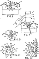
- a single use mold shown generally at 30 for forming conductor-to-conductor welded connections.
- the conductors illustrated are in the form of stranded cable such as seen at 31 and 32 with the ends to be joined entering the mold through inclined projecting guide sleeves 33 and 34, respectively, the ends projecting into the weld chamber 35.
- the single use mold is supported in a recess 36 in a base plate or fixture 37.
- the open top 39 of the mold forms a projecting annular rim 40 and a crucible assembly shown generally at 42 may be positioned on top of the mold when supported on the fixture.
- the crucible assembly includes a downwardly projecting nozzle 43 which projects into the open top 39 and includes a shoulder around the nozzle with seats on the mold rim 40. In this manner the crucible is supported by the mold in its upright position illustrated in Fig. 1.
- the crucible is formed of refractory blocks, one of which is illustrated.
- the blocks mate on a parting plane which is the same as the plane of Fig. 1.
- the faces of the blocks which form the parting plane have recesses which form a reaction chamber 45 and a vertically extending sprue or tap hole 46.
- the reaction chamber includes a charge of exothermic material seen at 47 supported on steel discs 48 at the shoulder between the reaction chamber and tap hole,
- the reaction chamber is closed by a lid 49 which may include a funnel hole 50 through which starting powder is introduced to the top of the exothermic material and through which ignition may be achieved by a flint gun, for example.
- a lid 49 which may include a funnel hole 50 through which starting powder is introduced to the top of the exothermic material and through which ignition may be achieved by a flint gun, for example.
- the exothermic material produces a reaction forming a molten metal which drops through the sprue hole 47 when the disc 48 is fused.
- the molten metal drops into the weld chamber 35 forming a high ampacity, low resistance electrical connection between the cables 31 and 32.
- the crucible and fixtures may then be removed and the single purpose mold may be left in place or broken away.
- the mold is made of a frangible refractory material and is not intended to be used again to form additional connections as are conventional reusable graphite molds, for example.
- the single use refractory frangible mold 30 may include four quadrant spaced guide sleeves projecting from the refractory body.
- the guide sleeves are shown as reading clockwise at 33, 52, 34 and 53. It will be noted that each extends from inside the weld chamber 35 to the exterior of the refractory body portion of the mold projecting a substantial distance.
- the angle of inclination from the horizontal and the projection distance from the weld chamber is such as to ensure that the outer lip or edge of the guide sleeves at 54 is above the molten metal within the weld chamber during the welding process. This avoids the problem of leakage.
- the inside diameter of the guide sleeves is selected to be larger than the largest conductor or cable designed to be used with the mold.
- a single type or size of mold may accommodate a wide range of sizes of conductor.
- Fig. 4 illustrates two relatively small cables indicated at 56 and 57 inserted into the inclined guide sleeves. The clearance between the inside diameter of the sleeves and the smaller cables 56 and 57 is readily apparent. However, even with the larger cable 58 seen in Fig. 5, a significant amount of clearance is still provided so that the weld chamber is always well vented.
- the refractory material may be pressed around the outside of the guide sleeves, or the holes formed and the sleeves inserted after formation.
- the single purpose mold illustrated is a combination or composite of a refractory body with the inclined projecting metal guide sleeves.
- the guide sleeves may, for example, be either copper or steel.
- up to four cable ends may be welded to each other each at the inclined angle illustrated forming in effect two right angle Vs with the weld metal at the intersections.
- the same mold will of course weld two cables, generally aligned or at right angles to each other with the guide sleeves not used simply left empty. It will also connect three cables in the form of a T.
- the illustrated mold has two opposed pairs of guide sleeves, or four altogether.
- the frangible refractory body may be formed of a variety of materials such as shown in the noted prior Gelfand U.S. Patent 3,020,608. These refractory materials may, for example, include fired clays, sand molds, bonded calcined dolomite, graphite molds, or refractory glass. Sand molds may be formed in a variety of ways as in foundry mold or core processes. These may include a variety of binder systems and include no-bake, heat cured, and cold box binder systems. In the no-bake and cold box processes, the binder is cured at room temperature.
- An exemplary sand-binder system formulation may be:
- Figs. 6, 7 and 8 there is illustrated the process of use of the single purpose mold embodiment seen in Figs. 1-5.
- the mold is positioned in recess 36 in the surface 60 of fixture 37.
- the fixture simply serves as a base plate holding the mold against movement while the operator inserts the cable ends and prepares and installs the crucible in the proper position.
- the recess 36 includes a center circular portion 61 and inclined quadrant spaced edge ramps 62 which accommodate the projecting inclined guide sleeves. Accordingly, when the single purpose mold 30 is positioned in the recess as shown, it is firmly supported by the fixture against horizontal movement and also supported against axial rotation because of the interfitting of the guide sleeves with the inclined ramps. When thus supported, the cable ends seen at 64, 65, 66 and 67 may be inserted in the respective guide sleeves.
- the crucible 42 is positioned on top of the single purpose mold 30.
- the charge of exothermic material is ignited by the igniter shown generally at 72 which include an integral hood 73 and a flint gun 74.
- the hood 73 includes a skirt 75 which telescopes over the top of the lid of the crucible seen in Fig. 1. The igniter reduces smoke and sparks which may result from the exothermic process.
- the molten metal formed by the process fuses the disc inside the crucible and the molten metal flows down through the sprue hole of the crucible into the top of the single purpose mold 30 and into the weld chamber forming a high ampacity, low resistance electrical connection.
- the molten weld metal will also fuse the inner ends of the metal guide sleeves and such sleeves serve to protect annealed cable ends acting as heat sinks and avoiding thermal shock.
- the crucible is removed, cleaned and recharged.
- the electrical connection made is as shown in Fig. 8.
- the single purpose mold 30 may be left in place or it may be broken away.
- Figs. 9-13 there is illustrated another type of single purpose molds shown generally at 80.
- the purpose of the mold 80 is to weld one or two conductors shown at 81 and 82 in Figs. 12 and 13 to a vertical metal surface 83, which, as illustrated, may be the web of a steel column 84.
- the mold 30 is in the form of a right circular cylindrical cup having an open top and a closed bottom
- the mold 80 for the most part, has a body with an exterior surface 86 also in the form of a right circular cylinder.
- the top 87 and the bottom 88 of the mold are perpendicular to the axis of that cylindrical surface, and of course parallel to each other.
- the mold also includes an exterior flat secant surface 90 which starts essentially at one edge of the top 87 as seen at 91 and forms a chord 92 with the otherwise circular bottom 88.
- the surface 90 may extend at approximately 10° to the axis of the cylindrical surface 86.
- the top of the mold is provided with a circular recess seen at 94 which terminates in an annular shoulder 95.
- the axis of the recess may be tilted approximately 10° from the axis of the cylindrical surface 86 and thus be about 80° from the plane of the top 87.
- Leading from the center of the recess 94 is an inclined tap hole 97 which leads to weld chamber 98.
- the axis of the tap hole 97 is approximately 30° from the axis of the cylindrical surface 86 and such axis is aimed at the approximate center of the somewhat elliptical opening 99 formed by the intersection of the weld chamber 98 and the secant surface 90.
- Entering the weld chamber are two inclined metal guide sleeves 101 and 102.
- the mold 80 is a composite with the body being a refractory material such as a fired clay, sand mold, or glass while the inclined projecting guide sleeves are metallic such as copper or steel.
- the surface 83 to which the electrical connection is to be made may be provided with a magnetic fixture seen at 106 which may simply be a block of aluminum incorporating permanent magnets.
- the fixture is secured to the metal surface in the desired location and is provided with a notch 107 in the upper edge thereof.
- the notch seen more clearly in Fig. 10 includes a rear wedge surface 108 so that as the mold 80 is forced down into the notch 107 as indicated by the arrow 109 in Fig. 11, the secant surface will be forced by the wedge angle against the surface of the column web 83.
- the crucible 42 may be positioned on top of the mold with the tip of the nozzle 43 coming to bear against the shoulder 95.
- the previously prepared charge in the crucible is ignited as seen in Fig. 12.
- Fig. 13 the crucible and fixture have been removed leaving the two cable electrical connection illustrated on the face of the column web which is the background of the Figure. Again, the refractory portion of the mold may be left in place or broken away.
- the mold 112 comprises a generally cylindrical refractory body 113 having an open top 114. Slightly below the mid point of the cylindrical mold, the interior is provided with a slight step seen at 115 and the reduced interior diameter lower section 116 tapers into a half-dome bottom 117. This configuration is exposed to a diametrical axial plane through the mold because the opposite side stops at the step 118 slightly above the opposite step 115. The axial plane and step form a right angle notch.
- the tubular metal guide sleeves extend into the weld chamber 119 at an inclined angle as seen at 121 and 122 with the outer projecting lower edge of each at 123 being above the level of molten metal within the weld chamber.
- the cables 125 and 126 are to be welded to the edge of the laminate seen at 127.
- the mold is positioned in a two part fixture shown generally at 128 with the two parts 129 and 130 clamping the laminate transversely and forming a recess indicated at 132 to receive the mold 112.
- the step 118 of the mold will fit on top of the laminate edges as seen in Fig. 16. Since the overall laminate or bar thickness may be less than the half of the inside diameter of the weld chamber at the step, the clamp portion 130 is provided with a refractory insert 133 which has a recess like that seen at 116 and 117 facing the laminate face.
- the weld metal may run down both sides of the laminate edges and the portion of the weld being formed by the refractory insert 133 is shown at 135 in Fig. 16.
- the cable ends 125 and 126 are inserted, and the previously prepared crucible is inserted on top of the mold as seen at 42 in Fig. 15 with the bottom nozzle 43 entering the open top of the mold.
- the molten metal formed will form the weld seen in Fig. 16.
- the single use mold 112 may be left in place as shown or broken away.
- Fig. 17 there is illustrated another type of single use mold shown generally at 140 which comprises a refractory body 141 and inclined metal projecting guide sleeves 142 and 143.
- the top of the mold is provided with a recessed seat 145 for the crucible nozzle 43 and a tap hole 146 leads to weld chamber 147 which is open at the bottom.
- the bottom of the mold adjacent the weld chamber opening may be provided with curved or beveled surfaces seen at 148 and 149 which permit the mold to seat on a rod 150. If the rod has irregular surfaces such as a concrete reinforcing bar, a fiberglass or like compressible refractory gasket may be employed surrounding the opening of the weld chamber to the rod 150.
- the exterior of the mold is provided with slots seen at 152 and 153 adapted to interfit with the tines of a fixture holding the mold to the bar.
- a mold like the mold 80 may be employed but with a curved secant surface corresponding generally to the curved surface of the bar.
- the mold may be clamped to the bar, the cable inserted through the oversized sleeving 142 and 143 with the crucible then seated in the top of the single use mold.
- the exothermic material when ignited flows into the mold to form an electrical connection between one or two conductors or cable and the rod 150.
- Figs. 18 and 19 illustrate yet another type of mold shown generally at 160.
- the mold 160 includes a refractory cylindrical cup-shape body 161 having a top rim 162. Projecting through the cylindrical body are the two metal guide sleeves 163 and 164, the inclination and extent of which is such that the upper outer lower edge of each seen at 165 is above the weld metal.
- the open top with the rim 162 accommodates the nozzle of the crucible while the bottom is provided with a hole indicated at 167.
- the hole 167 in effect forms the bottom of the weld chamber 168.
- the sleeving passages formed by the guide sleeves 163 and 164 are slightly offset from the center of the mold so that the molten metal will not impinge directly on the cable ends and guide sleeving so that the molten metal will not prematurely cool.
- the mold 160 of Figs. 18 and 19 is designed to be inserted on the stud 170 of a grounding plate 171 shown inverted in Fig. 20.
- the end of the stud enters the opening 167 and closes the bottom of the weld chamber.
- the cables 173 and 174 are inserted in the mold as indicated by the arrow 175.
- the mold is then ready for positioning of the crucible as seen in Fig. 21 and the igniter 74 will ignite the prepared charge permitting the molten metal to form and enter the weld chamber welding the conductors 173 and 174 to the ground plate 171.
- the mold 160 may also be employed to weld conductors or cable to the flat face of horizontal bar or laminate. As seen in Fig. 22, the mold is positioned onto the face 177 of laminate or bar 178, as indicated by the arrow 179. After one or both cables or conductors are positioned as seen, the crucible 42 previously filled with the welding metal composition, is mounted on the mold with the nozzle entering the top. The igniter is then used to create the exothermic reaction with the molten metal entering the mold and welding one or both conductors to the face of the laminate or bar.
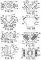
- FIG. 23 there is a mold 182 similar to the molds 140 and 160 in that it has an open bottom 183 which is surrounded by a compressible refractory material shown at 184 which may be adhered to the bottom of the refractory mold 182 as indicated at 185.
- the mold is provided with inclined metal sleeves 186 and 187 each having outer flared ends shown at 188 and 189, respectively.
- the flared ends seat at the outer end of passages 190 and 191 respectively, provided in lateral inclined extensions 192 and 193 of the mold.
- the extensions support the inclined sleeves and the outer ends of the extensions seat the flared ends of the metal guide sleeves properly spacing and positioning them within in the weld chamber 194.
- the mold includes the open top at the rim 195 which accommodates the crucible as shown in Figure 21.
- the mold of Figures 23 and 24 may be used as shown in Figures 20 or 22, or may be used with a clamping fixture to weld earthing conductors to metal rods as seen in Figure 17.
- the flared ends of the sleeves not only facilitate the insertion of the conductor into the mold, but they provide better support for the conductor and also improve positioning and retention of the sleeve within the mold.
- FIG. 25 With reference to Figure 25 there is illustrated a similar mold 198, but which has a closed bottom 199.
- Metal sleeves extend from the weld chamber 200 as indicated at 201 and 202 through lateral mold extensions 203 and 204 respectively, and each sleeve includes the flared outer end as seen at 205 and 206.
- the open top of the mold is provided with a rim 207 which seats the crucible.
- the mold 198 as seen in Figure 25 may be utilized on any substantially horizontal surface for the welding of conductors, or it may be utilized with a fixture such as seen in Figure 7.
- FIGs 26 and 27 there is illustrated a mold 210 having a weld chamber 211 which is open laterally as indicated at 212.
- the side of the mold which contains the opening 212 includes one planar surface 213 and a recessed planar surface 214.
- the offset as indicated at 215 and the recessed face 214 has secured thereto an L-shape compressible refractory seal seen at 216.
- the mold also includes the lateral extensions 217 and 218 through which the metal sleeves 219 and 220 extend with the flared outer ends 221 and 222, respectively, projecting from the mold.
- the open top of the mold provides a seat 224 for the crucible.
- the mold will weld one or two conductors to the metal surface against which the mold is clamped .
- a fixture such as seen in Figures 11 and 12 may be utilized for the purpose of supporting the mold while the connection is made.
- the flared ends of the metal sleeve seated in the outer V-shape extensions of the refractory mold provide better support and retention for the sleeves if assembled with the disposable refractory mold after formation of the mold.
- the extensions also assist in providing a gauge stop for the sleeves upon insertion. This sets the relative positioning and spacing of the inner ends of the sleeve within the weld chamber. They also ensure the absence of metal leakage when welding small cables.
- the single use refractory mold 231 includes a weld chamber 232 having an open top 233 forming a rim at 234 to seat the crucible nozzle 43 as seen in Figure 29.
- the mold includes lateral extensions 236 and 237 which include at the outer ends thereof the figure-eight holes seen at 238 and 239 in Figure 31, each of which accommodate side-by-side coil springs.
- the hole 239 accommodates coil springs 241 and 242.
- the hole 238 accommodates springs 243 and 244.
- Each coil spring has a flared or enlarged outer end as seen et 246 and 247. The flared outer end wedges into the appropriate end of the figure-eight openings retaining the springs in place when inserted and also properly positioning the springs so that the inner ends project into the weld chamber as shown and are properly seated and spaced.
- the figure-eight openings may likewise be slightly flared to accommodate the flare of the spring.
- the spring flare holds the spring in place and also serves as a guide sleeve to enable the cable, large or small, readily to be inserted into the mold.
- the coil spring also provides more lateral resilient support for the cable ends which may be bent or flexible.
- the springs may be, for example, made of steel which is nickel plated.
- the mold illustrated in Figures 28 through 31 accommodates up to four cables through the spring sleeves paired opposite each other. Not all holes or sleeves need be used.
- Figure 32 illustrates a weld connection made indicated generally at 250.
- the weld includes the mass of weld metal 251 which has fused together the springs 242 and 244 as well as the respective cables 252 and 253 projecting therefrom. It is noted for illustration purposes that the cables 252 and 253 are not the same size. In any event, with the mold illustrated, a four cable connection can quickly be made with the connected cables extending paired and generally parallel to each other.
- the composite refractory-coil spring mold assembly may either be left in place or removed. If removed, the coil springs remain in place as seen in Figure 32.
- the mold in elevation achieves a generally Y-shape, or perhaps a shape more similar to the Greek letter Psi ( ⁇ ).
Landscapes
- Engineering & Computer Science (AREA)
- Mechanical Engineering (AREA)
- Crucibles And Fluidized-Bed Furnaces (AREA)
- Manufacture And Refinement Of Metals (AREA)
Applications Claiming Priority (4)
| Application Number | Priority Date | Filing Date | Title |
|---|---|---|---|
| US63466896A | 1996-04-18 | 1996-04-18 | |
| US634668 | 1996-04-18 | ||
| US08/752,903 US5715886A (en) | 1996-04-18 | 1996-11-20 | Single use welding mold and method |
| US752903 | 1996-11-20 |
Publications (2)
| Publication Number | Publication Date |
|---|---|
| EP0802014A2 true EP0802014A2 (fr) | 1997-10-22 |
| EP0802014A3 EP0802014A3 (fr) | 1998-01-14 |
Family
ID=27092206
Family Applications (1)
| Application Number | Title | Priority Date | Filing Date |
|---|---|---|---|
| EP97106212A Ceased EP0802014A3 (fr) | 1996-04-18 | 1997-04-16 | Moule à usage unique pour le soudage et procédé |
Country Status (3)
| Country | Link |
|---|---|
| US (1) | US5715886A (fr) |
| EP (1) | EP0802014A3 (fr) |
| BR (1) | BR9701855A (fr) |
Cited By (4)
| Publication number | Priority date | Publication date | Assignee | Title |
|---|---|---|---|---|
| EP1231012A1 (fr) * | 2001-02-01 | 2002-08-14 | Thomas & Betts International, Inc. | Assemblage de moule pour soudage exothermique |
| CN102709779A (zh) * | 2012-06-11 | 2012-10-03 | 江苏省电力公司南通供电公司 | 一种电缆中间接头的焊接模具 |
| CN107457500A (zh) * | 2017-09-19 | 2017-12-12 | 浙江昌泰电力电缆有限公司 | 一种适用于铜导体焊接的放热焊粉及其焊接方法 |
| US20190151984A1 (en) * | 2017-11-17 | 2019-05-23 | Orgo-Thermit Inc. | Rail Welding Crucible and Cap with an Oxygen/Propane Gas Rail-Preheating Burner Ignited Reaction Starter Mix |
Families Citing this family (23)
| Publication number | Priority date | Publication date | Assignee | Title |
|---|---|---|---|---|
| US5954261A (en) * | 1996-04-18 | 1999-09-21 | Erico International Corporation | Welding mold and method |
| US5829510A (en) * | 1996-04-18 | 1998-11-03 | Erico International Corporation | Exothermic welding crucible and method |
| DE19822851A1 (de) * | 1998-05-22 | 1999-11-25 | Rolf Ploetz | Transportabler Reaktionstiegel für eine metallothermische Schweißportion zum einmaligen Gebrauch |
| US6789724B2 (en) * | 2001-07-06 | 2004-09-14 | Erico International Corporation | Welding apparatus and method |
| DE60325939D1 (de) * | 2002-01-25 | 2009-03-12 | Erico Int Corp | Schweissvorrichtung |
| US6776386B1 (en) | 2002-03-21 | 2004-08-17 | Continental Industries, Inc. | Lid for exothermic reaction welding mold |
| US6793003B2 (en) * | 2002-03-25 | 2004-09-21 | Thomas & Betts International, Inc. | Exothermic welding mold conversion plug |
| US6994244B2 (en) * | 2003-05-07 | 2006-02-07 | Harger, Inc. | Exothermic welding |
| US20070017955A1 (en) * | 2005-07-25 | 2007-01-25 | Siracki Glenn T | Weld metal material apparatus and method |
| US7240717B2 (en) * | 2005-11-17 | 2007-07-10 | Continental Industries, Inc. | Multiple ignition source exothermic reaction mold device |
| GB2452774A (en) * | 2007-09-17 | 2009-03-18 | T K Technology Co Ltd | Technique for forming titanium alloy tubes |
| US7950568B2 (en) * | 2008-01-04 | 2011-05-31 | Harger, Inc. | Exothermic welding assembly |
| US8336865B2 (en) | 2009-11-24 | 2012-12-25 | At&T Intellectual Property I, L.P. | Methods, systems, and products for welding grounding rods |
| US7946466B1 (en) * | 2009-12-07 | 2011-05-24 | Continental Industries, Inc. | Alternative ignition source system for an exothermic reaction mold device |
| US7975900B2 (en) * | 2009-12-07 | 2011-07-12 | Continental Industries, Inc. | Ignition source system for an exothermic reaction mold device |
| ES2402480B1 (es) * | 2011-10-20 | 2014-05-09 | Klk Electro Materiales, S.L.U. | Dispositivo y procedimiento para encendido a distancia en soldadura aluminotérmica |
| CN103934586A (zh) * | 2014-04-23 | 2014-07-23 | 宁波邦和新材料有限公司 | 悬索桥主缆缠丝焊接装备 |
| EP3285955B1 (fr) * | 2015-04-24 | 2019-10-23 | Hubbell Incorporated | Moules de soudure par réaction exothermique, cartouches contenant du métal d'apport pour ces moules, et procédés d'utilisation |
| US10583522B2 (en) | 2016-06-03 | 2020-03-10 | Hubbell Incorporated | Tools for use in confined spaces |
| CN106181023B (zh) * | 2016-08-22 | 2018-09-14 | 洛阳双瑞橡塑科技有限公司 | 一种钢轨铝热焊接浇注系统 |
| WO2019095098A1 (fr) * | 2017-11-14 | 2019-05-23 | 四川桑莱特智能电气设备股份有限公司 | Dispositif de soudage exothermique et procédé de soudage exothermique |
| US20200307048A1 (en) * | 2019-03-26 | 2020-10-01 | HubbellI Incorporated | Molds for making protective coverings over metal structures |
| CN110227883B (zh) * | 2019-06-10 | 2023-10-13 | 河北华友文化遗产保护股份有限公司 | 一种可调角度的放热焊模具 |
Family Cites Families (5)
| Publication number | Priority date | Publication date | Assignee | Title |
|---|---|---|---|---|
| US2957214A (en) * | 1958-11-26 | 1960-10-25 | Continental Ind Inc | Exothermic welding method |
| US3020608A (en) * | 1959-07-13 | 1962-02-13 | Erico Prod Inc | Frangible mold |
| US3782677A (en) * | 1971-04-05 | 1974-01-01 | Erico Prod Inc | Cable and like splicing apparatus |
| US5145106A (en) * | 1989-08-03 | 1992-09-08 | Erico International Corporation | Welding apparatus and method |
| US5582228A (en) * | 1995-04-20 | 1996-12-10 | Erico International Corporation | Exothermic welding crucible and method |
-
1996
- 1996-11-20 US US08/752,903 patent/US5715886A/en not_active Expired - Fee Related
-
1997
- 1997-04-16 EP EP97106212A patent/EP0802014A3/fr not_active Ceased
- 1997-04-18 BR BR9701855A patent/BR9701855A/pt not_active Application Discontinuation
Cited By (6)
| Publication number | Priority date | Publication date | Assignee | Title |
|---|---|---|---|---|
| EP1231012A1 (fr) * | 2001-02-01 | 2002-08-14 | Thomas & Betts International, Inc. | Assemblage de moule pour soudage exothermique |
| US6640873B2 (en) | 2001-02-01 | 2003-11-04 | Thomas & Betts International, Inc. | Exothermic weld mold assembly |
| CN102709779A (zh) * | 2012-06-11 | 2012-10-03 | 江苏省电力公司南通供电公司 | 一种电缆中间接头的焊接模具 |
| CN107457500A (zh) * | 2017-09-19 | 2017-12-12 | 浙江昌泰电力电缆有限公司 | 一种适用于铜导体焊接的放热焊粉及其焊接方法 |
| US20190151984A1 (en) * | 2017-11-17 | 2019-05-23 | Orgo-Thermit Inc. | Rail Welding Crucible and Cap with an Oxygen/Propane Gas Rail-Preheating Burner Ignited Reaction Starter Mix |
| US10464164B2 (en) * | 2017-11-17 | 2019-11-05 | Orgo-Thermit Inc. | Rail welding crucible and cap with an oxygen/propane gas rail-preheating burner ignited reaction starter mix |
Also Published As
| Publication number | Publication date |
|---|---|
| EP0802014A3 (fr) | 1998-01-14 |
| US5715886A (en) | 1998-02-10 |
| BR9701855A (pt) | 1998-11-10 |
Similar Documents
| Publication | Publication Date | Title |
|---|---|---|
| EP0802014A2 (fr) | Moule à usage unique pour le soudage et procédé | |
| EP0802013A1 (fr) | Moule pour soudage et procédé | |
| CA2369646C (fr) | Moule de soudage exothermique | |
| US7240717B2 (en) | Multiple ignition source exothermic reaction mold device | |
| CA1239010A (fr) | Coulee du metal | |
| US6793003B2 (en) | Exothermic welding mold conversion plug | |
| EP1273381A1 (fr) | Appareil de soudage et procédé pour réaliser des connexions électriques | |
| EP0875330A1 (fr) | Processus exthermique et méthode et méthode de mise en oeuvre | |
| US5653279A (en) | Apparatus and method for forming electrical connections | |
| CA1088175A (fr) | Cosse de cable et methode de fabrication | |
| EP0802015A2 (fr) | Creuset pour le soudage exothermique et procédé | |
| US5241737A (en) | Method of making a composite casting | |
| EP0140512A1 (fr) | Méthode de prise d'échantillons de métal liquide | |
| US5582228A (en) | Exothermic welding crucible and method | |
| US3554270A (en) | Metal casing apparatus and method | |
| US20050230076A1 (en) | System and method for termination of a wire rope | |
| EP0099190B1 (fr) | Prise d'échantillon | |
| EP0870568A1 (fr) | Méthode et appareil pour le soudage de bandes | |
| US3262163A (en) | Cast welding apparatus and method | |
| EP0610888A2 (fr) | Dispositif et procédé de soudage de connecteur de mise à la terre à une structure en acier | |
| EP4357048A1 (fr) | Appareil et procédé pour couler des pièces métalliques | |
| EP4610620A1 (fr) | Unité d'échantillonnage pour un système d'échantillonnage et procédé de prélèvement d'échantillons d'aluminium fondu dans une installation de production d'aluminium primaire | |
| EP4610649A1 (fr) | Système d'échantillonnage et procédé de prélèvement d'échantillons d'aluminium fondu dans une installation de production d'aluminium primaire | |
| WO2004010548A1 (fr) | Piece encastree de moule | |
| WO2019178405A1 (fr) | Moule de soudage modulaire |
Legal Events
| Date | Code | Title | Description |
|---|---|---|---|
| PUAI | Public reference made under article 153(3) epc to a published international application that has entered the european phase |
Free format text: ORIGINAL CODE: 0009012 |
|
| AK | Designated contracting states |
Kind code of ref document: A2 Designated state(s): AT BE CH DE DK ES FI FR GB GR IE IT LI LU NL PT SE |
|
| PUAL | Search report despatched |
Free format text: ORIGINAL CODE: 0009013 |
|
| AK | Designated contracting states |
Kind code of ref document: A3 Designated state(s): AT BE CH DE DK ES FI FR GB GR IE IT LI LU NL PT SE |
|
| 17P | Request for examination filed |
Effective date: 19980130 |
|
| 17Q | First examination report despatched |
Effective date: 19990901 |
|
| GRAG | Despatch of communication of intention to grant |
Free format text: ORIGINAL CODE: EPIDOS AGRA |
|
| STAA | Information on the status of an ep patent application or granted ep patent |
Free format text: STATUS: THE APPLICATION HAS BEEN REFUSED |
|
| 18R | Application refused |
Effective date: 20010930 |