EP0801448B1 - Laserabordnung zur Erzeugung eines Haupt- und eines Referenzlichtstrahls - Google Patents
Laserabordnung zur Erzeugung eines Haupt- und eines Referenzlichtstrahls Download PDFInfo
- Publication number
- EP0801448B1 EP0801448B1 EP97104308A EP97104308A EP0801448B1 EP 0801448 B1 EP0801448 B1 EP 0801448B1 EP 97104308 A EP97104308 A EP 97104308A EP 97104308 A EP97104308 A EP 97104308A EP 0801448 B1 EP0801448 B1 EP 0801448B1
- Authority
- EP
- European Patent Office
- Prior art keywords
- laser diode
- laser
- light
- substrate
- arrangement
- Prior art date
- Legal status (The legal status is an assumption and is not a legal conclusion. Google has not performed a legal analysis and makes no representation as to the accuracy of the status listed.)
- Expired - Lifetime
Links
Images

Classifications
-
- H—ELECTRICITY
- H01—ELECTRIC ELEMENTS
- H01S—DEVICES USING THE PROCESS OF LIGHT AMPLIFICATION BY STIMULATED EMISSION OF RADIATION [LASER] TO AMPLIFY OR GENERATE LIGHT; DEVICES USING STIMULATED EMISSION OF ELECTROMAGNETIC RADIATION IN WAVE RANGES OTHER THAN OPTICAL
- H01S5/00—Semiconductor lasers
- H01S5/02—Structural details or components not essential to laser action
- H01S5/022—Mountings; Housings
- H01S5/0225—Out-coupling of light
- H01S5/02251—Out-coupling of light using optical fibres
-
- H—ELECTRICITY
- H01—ELECTRIC ELEMENTS
- H01S—DEVICES USING THE PROCESS OF LIGHT AMPLIFICATION BY STIMULATED EMISSION OF RADIATION [LASER] TO AMPLIFY OR GENERATE LIGHT; DEVICES USING STIMULATED EMISSION OF ELECTROMAGNETIC RADIATION IN WAVE RANGES OTHER THAN OPTICAL
- H01S5/00—Semiconductor lasers
- H01S5/005—Optical components external to the laser cavity, specially adapted therefor, e.g. for homogenisation or merging of the beams or for manipulating laser pulses, e.g. pulse shaping
-
- H—ELECTRICITY
- H01—ELECTRIC ELEMENTS
- H01S—DEVICES USING THE PROCESS OF LIGHT AMPLIFICATION BY STIMULATED EMISSION OF RADIATION [LASER] TO AMPLIFY OR GENERATE LIGHT; DEVICES USING STIMULATED EMISSION OF ELECTROMAGNETIC RADIATION IN WAVE RANGES OTHER THAN OPTICAL
- H01S5/00—Semiconductor lasers
- H01S5/02—Structural details or components not essential to laser action
- H01S5/022—Mountings; Housings
- H01S5/023—Mount members, e.g. sub-mount members
- H01S5/02325—Mechanically integrated components on mount members or optical micro-benches
Definitions
- the invention relates to a laser arrangement with a a laser diode arranged to produce a substrate main light beam emerging from a main opening.
- Main light beam is coupled into an optical fiber, which is provided with a Y-coupler, which feeds it Amount of light into a main beam and one Split reference light beam.
- An object of the invention is a laser arrangement of the type mentioned in such a way that the Coupling of both a main and reference light beam without the use of a Y-coupler.
- this object is achieved in that the Laser diode at least on several sides of high material Surrounded reflectivity, which is arranged such that one not used to form the main light beam Proportion of light generated by the laser diode with mixed modes is reflected or scattered several times, and that a passage from the main opening defined reference light portion allowing reference opening is provided.
- part of the laser diode generated light already in the laser arrangement from the main light beam separated and to form a reference light beam used.
- the laser diode for example on one side, preferably on the back provided with an additional light outlet opening be from which the for the formation of the reference light beam required amount of light can escape.
- the specified proportion of light is then after the laser diode emerges from the reflective material provided according to the invention several times reflected or scattered, creating a mix of modes occurs.
- the light reflected or scattered in this way occurs then out of the laser arrangement through the reference opening and forms the desired reference light beam.
- a laser arrangement according to the invention can thus, for example both an optical fiber for the main light beam as well as an optical fiber for the reference light beam directly - without using a Y-coupler be, whereby both the to be operated economic effort as well as the required space can be reduced in an advantageous manner.
- the mode of action of this preferred embodiment of the invention corresponds an Ulbricht sphere, the one in an Ulbricht sphere usually existing aperture in the present case the aforementioned relative arrangement of laser diode and reference opening is replaced.
- the function of the aperture in the Ulbricht sphere is to prevent that Light reaches the exit opening directly from the light source.
- the material surrounding the laser diode according to the invention can a reflectivity greater than 0.8, in particular greater than 0.9 and preferably have between 0.96 and 0.99.
- the substrate also has a corresponding has high reflectivity.
- a further layer of high reflectivity is provided on the side of the laser diode facing away from the substrate.
- the reflective substrate as well the opposite additional reflective layer the back of the laser diode clearly over its length extend beyond and in this way a reflection and Scattering channel for exiting on the back of the laser diode Form light.
- the substrate and / or the additional one preferably exist reflective layer of ceramic, which in particular a has essential white color and is therefore well reflected.
- the housing can be designed as a hybrid housing, for example be, which is preferably on its inside has a golden color.
- the main light beam is preferably from between 90% and 99%, especially about 96% of that from the laser diode generated light.
- the reference light beam is preferably from 1% to 10%, in particular approximately 4% of that produced by the laser diode Light formed.
- the reference light beam has a beam angle between 30 ° and 50 °, in particular a radiation angle of approximately 40 °.
- Figure 1 shows a laser diode 1 with the edge area a ceramic substrate 2 is connected, which is Ceramic substrate 2 on the back 3 of the laser diode 1 clearly extends beyond their length.
- the longitudinal extension of the ceramic substrate 2 is approximately 8 times the longitudinal extent of the laser diode 1.
- a cover ceramic layer 4 is provided, the Dimensions essentially the dimensions of the ceramic substrate 2 correspond and which are parallel to the ceramic substrate 2 extends.
- the arrangement of laser diode 1, ceramic substrate 2 and Cover ceramic 4 thus corresponds to a sandwich construction, at which the laser diode L between the ceramic substrate 2 and the Cover ceramic 4 is arranged in the edge region.
- Ceramic substrate 2 and the cover ceramic 4 each of which extends over the longitudinal extent of the laser diode 1 extends, forms the desired fashion mix effecting reflection or scattering body for on the back 3 the laser diode 1 emerging light.
- ceramic substrate 2 and cover ceramic 4 are reflective, in particular, they have a white color.
- the laser diode L, ceramic substrate 2 and cover ceramic 4 existing arrangement is accommodated in a hybrid housing 5, which is largely complete the said arrangement encloses.
- the inside of the hybrid housing 5 is reflective, especially gold-colored, designed to this way the one desired for the reference light extraction Support effect of mode mixing.
- the hybrid housing 5 has a main opening 6 which is aligned with the laser diode 1 so that the the laser diode 1 outgoing main light beam directly through the main opening 6 can occur.
- the hybrid housing 5 with a reference opening 7 provided by which the reference light is coupled out.
- the reference opening 7 is outside the direct one Beam area of the laser diode 1 arranged so that basically only reflected or scattered light through the Can reach reference opening 7.
- the embodiment prevents the ceramic cover 4, that a light beam directly from the back 3 of the laser diode 1 can reach the reference opening 7.
- a transmission optical fiber 8 is introduced into the main opening 6, which is the main light beam from the shown Laser arrangement leads out.
- the Reference opening 7 introduced a reference optical fiber 9.
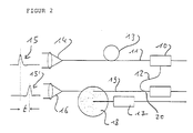
- Figure 2 shows the principle diagram of a range finder using a laser arrangement according to the invention.
- the transmitter 10 can, for example, according to FIG a transmission optical fiber 11 and a reference optical fiber 12 are coupled in the manner according to the invention.
- the light passing through the transmission optical fiber 11 experiences a delay or mode mixing at 13 and then arrives at a transmission optics 14, via which ultimately a main light pulse 15 generated by the transmitter 10 is emitted becomes.
- the received light pulse attenuated in this way is coupled into a receiving optical fiber 19.
- This Receiving optical fiber 19 is with a fiber coupler 20th equipped, via which the reference optical fiber 12 with the Receiving optical fiber 19 is connected.
Landscapes
- Physics & Mathematics (AREA)
- Condensed Matter Physics & Semiconductors (AREA)
- General Physics & Mathematics (AREA)
- Electromagnetism (AREA)
- Optics & Photonics (AREA)
- Optical Radar Systems And Details Thereof (AREA)
- Optical Couplings Of Light Guides (AREA)
- Semiconductor Lasers (AREA)
- Lasers (AREA)
- Laser Surgery Devices (AREA)
- Optical Elements Other Than Lenses (AREA)
Description
- Figur 1
- eine schematisierte Querschnittsdarstellung durch eine erfindungsgemäße Laseranordnung und
- Figur 2
- ein Prinzipschaubild eines Entfernungsmessers unter Verwendung einer erfindungsgemäßen Laseranordnung.
Claims (10)
- Laseranordnung mit einer auf einem Substrat (2) angeordneten Laserdiode (1) zur Erzeugung eines aus einer Hauptöffnung (6) austretenden Hauptlichtstrahls,
dadurch gekennzeichnet, daß die Laserdiode (1) zumindest auf mehreren Seiten von Material hoher Reflektivität umgeben ist, welches derart angeordnet ist, daß ein nicht zur Bildung des Hauptlichtstrahls verwendeter Anteil des von der Laserdiode (1) erzeugten Lichts zur Bildung eines Referenzlichtanteils unter Modenmischung mehrfach reflektiert bzw. gestreut wird, und daß entfernt von der Hauptöffnung (6) eine den Durchtritt eines definierten Referenzlichtanteils gestattende Referenzöffnung (7) vorgesehen ist. - Laseranordnung nach Anspruch 1,
dadurch gekennzeichnet, daß die Referenzöffnung (7) außerhalb des direkten Abstrahlbereichs der Laserdiode (1) angeordnet ist, so daß nur reflektiertes bzw. gestreutes Licht durch die Referenzöffnung (7) gelangen kann, und/oder daß die Hauptöffnung (6) innerhalb des direkten Abstrahlbereichs der Laserdiode (1) angeordnet ist. - Laseranordnung nach einem der vorhergehenden Ansprüche,
dadurch gekennzeichnet, daß das die Laserdiode (1) umgebende Material eine Reflektivität größer 0,8, insbesondere größer 0,9 und bevorzugt zwischen 0,96 und 0,99 besitzt, und/oder daß das Substrat (2) ebenfalls eine hohe Reflektivität besitzt. - Laseranordnung nach einem der vorhergehenden Ansprüche,
dadurch gekennzeichnet, daß auf der dem Substrat (2) abgewandten Seite der Laserdiode (1) eine zusätzliche Schicht (4) hoher Reflektivität angeordnet ist, wobei sich insbesondere das reflektierende Substrat (2) sowie die gegenüberliegende zusätzliche Schicht (4) an der Rückseite (3) der Laserdiode (1) deutlich über deren Länge hinaus erstrecken und so einen Reflexions- und Streukanal für auf der Rückseite (3) der Laserdiode (1) austretendes Licht bilden. - Laseranordnung nach einem der vorhergehenden Ansprüche,
dadurch gekennzeichnet, daß das Substrat (2) aus einem Keramiksubstrat besteht. - Laseranordnung nach einem der Ansprüche 4 oder 5,
dadurch gekennzeichnet, daß die zusätzliche Schicht (4) von einer Deckkeramik gebildet ist, wobei insbesondere Substratkeramik (2) und Deckkeramik (4) eine in etwa weiße Farbe aufweisen. - Laseranordnung nach einem der vorhergehenden Ansprüche,
dadurch gekennzeichnet, daß die Anordnung in einem innenseitig reflektierenden Gehäuse (5) untergebracht ist, wobei insbesondere das Gehäuse (5) als Hybridgehäuse ausgebildet ist und/oder das Gehäuse (5) auf seiner Innenseite eine goldene Farbe besitzt. - Laseranordnung nach einem der vorhergehenden Ansprüche,
dadurch gekennzeichnet, daß die Laserdiode (1) auf ihrer Vorder- und/oder Rückseite (3) verspiegelt ist, und/oder daß der Hauptlichtstrahl von zwischen 90% und 99%, vorzugsweise von ungefähr 96% des von der Laserdiode (1) erzeugten Lichts gebildet ist, und/oder daß der Referenzlichtstrahl von zwischen 1% und 10%, vorzugsweise von ungefähr 4% des von der Laserdiode (1) erzeugten Lichts gebildet ist. - Laseranordnung nach einem der vorhergehenden Ansprüche,
dadurch gekennzeichnet, daß der Referenzlichtstrahl einen Abstrahlwinkel zwischen 30° und 50°, insbesondere von ungefähr 40° besitzt, und/oder daß an der Haupt- und/oder Referenzöffnung (6, 7) eine Lichtleitfaser (8, 9, 11, 12) angeordnet ist, in die das durch die jeweilige Öffnung (6, 7) tretende Licht eingekoppelt wird, und/oder daß auf dem Substrat (2) eine Ansteuerschaltung für die Laserdiode (1) angeordnet ist. - Vorrichtung zur Entfernungsmessung mittels Lichtpuls-Laufzeitverfahren, mit einer Meßstrecke (11, 13, 19) und einer Referenzstrecke (12),
dadurch gekennzeichnet, daß eine Laseranordnung (10) nach einem der Ansprüche 1 bis 19 vorgesehen ist, wobei die Meßstrecke (11, 13, 19) über die Hauptöffnung (6) und die Referenzstrecke (12) über die Referenzöffnung (7) der Laseranordnung mit Licht beaufschlagt ist.
Applications Claiming Priority (2)
| Application Number | Priority Date | Filing Date | Title |
|---|---|---|---|
| DE19614526 | 1996-04-12 | ||
| DE19614526A DE19614526A1 (de) | 1996-04-12 | 1996-04-12 | Laseranordnung zur Erzeugung eines Haupt- und eines Referenzlichtstrahls |
Publications (3)
| Publication Number | Publication Date |
|---|---|
| EP0801448A2 EP0801448A2 (de) | 1997-10-15 |
| EP0801448A3 EP0801448A3 (de) | 1999-03-10 |
| EP0801448B1 true EP0801448B1 (de) | 2001-10-31 |
Family
ID=7791113
Family Applications (1)
| Application Number | Title | Priority Date | Filing Date |
|---|---|---|---|
| EP97104308A Expired - Lifetime EP0801448B1 (de) | 1996-04-12 | 1997-03-13 | Laserabordnung zur Erzeugung eines Haupt- und eines Referenzlichtstrahls |
Country Status (3)
| Country | Link |
|---|---|
| EP (1) | EP0801448B1 (de) |
| AT (1) | ATE208088T1 (de) |
| DE (2) | DE19614526A1 (de) |
Families Citing this family (3)
| Publication number | Priority date | Publication date | Assignee | Title |
|---|---|---|---|---|
| DE19823330C1 (de) * | 1998-05-26 | 1999-09-16 | Leuze Electronic Gmbh & Co | Laseranordnung |
| DE19844506C1 (de) * | 1998-09-29 | 2000-06-29 | Leuze Electronic Gmbh & Co | Laseranordnung und diese umfassende Vorrichtung zur Entfernungsmessung |
| GB2518454A (en) * | 2013-09-24 | 2015-03-25 | St Microelectronics Res & Dev | Improvements in or relating to proximity sensors |
Family Cites Families (8)
| Publication number | Priority date | Publication date | Assignee | Title |
|---|---|---|---|---|
| US4817109A (en) * | 1985-12-10 | 1989-03-28 | 501 Sharp Kabushiki Kaisha | External resonator type semiconductor laser apparatus |
| JPH0654824B2 (ja) * | 1987-08-19 | 1994-07-20 | 日本電気株式会社 | アレイ型半導体レ−ザ装置 |
| US5023885A (en) * | 1988-09-20 | 1991-06-11 | Siemens Aktiengesellschaft | External optical resonator for a semiconductor laser |
| DE4022465A1 (de) * | 1990-07-14 | 1992-01-23 | Dornier Medizintechnik | Laserenergiemessung und -regelung |
| US5140599A (en) * | 1990-08-01 | 1992-08-18 | Hewlett-Packard Company | Optical oscillator sweeper |
| DE4109844C1 (en) * | 1991-03-26 | 1992-06-11 | Eltro Gmbh, Gesellschaft Fuer Strahlungstechnik, 6900 Heidelberg, De | Laser range finder with fibre=optic propagation time component - couples two glass fibres to photodiode, one being in closed ring form or bounded at both sides by reflectors |
| US5365537A (en) * | 1993-01-07 | 1994-11-15 | Clarion Co., Ltd. | Method of producing a semiconductor laser |
| DE4416717C1 (de) * | 1994-05-11 | 1995-12-07 | Siemens Ag | Anordnung als bidirektionales Sende- und Empfangsmodul |
-
1996
- 1996-04-12 DE DE19614526A patent/DE19614526A1/de not_active Withdrawn
-
1997
- 1997-03-13 DE DE59705134T patent/DE59705134D1/de not_active Expired - Lifetime
- 1997-03-13 AT AT97104308T patent/ATE208088T1/de not_active IP Right Cessation
- 1997-03-13 EP EP97104308A patent/EP0801448B1/de not_active Expired - Lifetime
Also Published As
| Publication number | Publication date |
|---|---|
| EP0801448A2 (de) | 1997-10-15 |
| ATE208088T1 (de) | 2001-11-15 |
| EP0801448A3 (de) | 1999-03-10 |
| DE19614526A1 (de) | 1997-10-16 |
| DE59705134D1 (de) | 2001-12-06 |
Similar Documents
| Publication | Publication Date | Title |
|---|---|---|
| EP0238977B1 (de) | Sende- und Empfangsmodul für ein bidirektionales Kommunikationsnetz, insbesondere ein Breitband-ISDN | |
| DE2834821C2 (de) | Einrichtung zum Überprüfen der Betriebseigenschaften von Laser-Entfernungsmeßgeräten | |
| DE2933245C2 (de) | Bidirektionales einfaseroptisches Signalübertragungssystem | |
| DE19932430C2 (de) | Opto-elektronische Baugruppe sowie Bauteil für diese Baugruppe | |
| EP1178341A2 (de) | Optisches bidirektionales Sende- und Empfangsmodul mit einem Stiftkörper mit integriertem WDM-Filter | |
| DE3031589A1 (de) | Vorrichtung zur schadensfeststellung in einer lichtleitfaser zur uebertragung von laserleistung | |
| EP1022187A2 (de) | Fahrzeugleuchte | |
| DE69011928T2 (de) | Ramankonverter und Ramanlasersysteme mit solchen Konvertern. | |
| EP0410143A2 (de) | Optelektrische Sende- und Empfangsvorrichtung | |
| DE3230570A1 (de) | Sende- und empfangseinrichtung fuer ein faseroptisches sensorsystem | |
| DE102018111438A1 (de) | Radom | |
| DE10222852A1 (de) | Streulichtschneidstruktur für optische Vorrichtung | |
| DE102008034052A1 (de) | Lichtleitkörper, insbesondere für ein Kraftfahrzeug | |
| DE1301865B (de) | Mehrfachreflexionsanordnung zur Kompression von Frequenzmodulierten Impulsen | |
| EP0104576A2 (de) | Optisches Kopplernetzwerk zum Verkoppeln von mehreren Teilnehmersendern mit mehreren Teilnehmerempfängern mittels optischer Sternkoppler | |
| DE102005010905A1 (de) | Objekterfassungsvorrichtung für ein Fahrzeug | |
| EP0262438B1 (de) | Lasersender mit einem Halbleiterlaser und einem externen optischen Resonator in Form eines frequenzselektiven Faserrichtkopplers | |
| DE60222736T2 (de) | Optisches Modul mit Monitor-Photodiode | |
| EP0801448A2 (de) | Laserabordnung zur Erzeugung eines Haupt- und eines Referenzlichtstrahls | |
| EP1832902A1 (de) | Flache Leuchtvorrichtung | |
| DE202012007402U1 (de) | Optoelektronischer Sensor | |
| WO2017174659A1 (de) | Lichtquelle für eine beieuchtungsvorrichtung sowie beleuchtungsvorrichtung mit einer derartigen lichtquelle | |
| EP1085252B1 (de) | Lichtleiterleuchte mit verbesserter Abschirmung | |
| DE102005009424A1 (de) | Optischer Sensor mit optimierter Sensitivität | |
| DE69017108T2 (de) | Baueinheit zur Verstärkung von Lichtsignalen in optischen Faserübertragungsleitungen. |
Legal Events
| Date | Code | Title | Description |
|---|---|---|---|
| PUAI | Public reference made under article 153(3) epc to a published international application that has entered the european phase |
Free format text: ORIGINAL CODE: 0009012 |
|
| AK | Designated contracting states |
Kind code of ref document: A2 Designated state(s): AT CH DE FR GB IT LI |
|
| PUAL | Search report despatched |
Free format text: ORIGINAL CODE: 0009013 |
|
| AK | Designated contracting states |
Kind code of ref document: A3 Designated state(s): AT CH DE FR GB IT LI |
|
| 17P | Request for examination filed |
Effective date: 19990511 |
|
| RIC1 | Information provided on ipc code assigned before grant |
Free format text: 7H 01S 5/022 A, 7G 01S 7/48 B |
|
| GRAG | Despatch of communication of intention to grant |
Free format text: ORIGINAL CODE: EPIDOS AGRA |
|
| GRAG | Despatch of communication of intention to grant |
Free format text: ORIGINAL CODE: EPIDOS AGRA |
|
| GRAG | Despatch of communication of intention to grant |
Free format text: ORIGINAL CODE: EPIDOS AGRA |
|
| GRAH | Despatch of communication of intention to grant a patent |
Free format text: ORIGINAL CODE: EPIDOS IGRA |
|
| 17Q | First examination report despatched |
Effective date: 20001122 |
|
| GRAH | Despatch of communication of intention to grant a patent |
Free format text: ORIGINAL CODE: EPIDOS IGRA |
|
| GRAA | (expected) grant |
Free format text: ORIGINAL CODE: 0009210 |
|
| AK | Designated contracting states |
Kind code of ref document: B1 Designated state(s): AT CH DE FR GB IT LI |
|
| PG25 | Lapsed in a contracting state [announced via postgrant information from national office to epo] |
Ref country code: IT Free format text: LAPSE BECAUSE OF FAILURE TO SUBMIT A TRANSLATION OF THE DESCRIPTION OR TO PAY THE FEE WITHIN THE PRE;WARNING: LAPSES OF ITALIAN PATENTS WITH EFFECTIVE DATE BEFORE 2007 MAY HAVE OCCURRED AT ANY TIME BEFORE 2007. THE CORRECT EFFECTIVE DATE MAY BE DIFFERENT FROM THE ONE RECORDED.SCRIBED TIME-LIMIT Effective date: 20011031 Ref country code: GB Free format text: LAPSE BECAUSE OF FAILURE TO SUBMIT A TRANSLATION OF THE DESCRIPTION OR TO PAY THE FEE WITHIN THE PRESCRIBED TIME-LIMIT Effective date: 20011031 Ref country code: FR Free format text: LAPSE BECAUSE OF FAILURE TO SUBMIT A TRANSLATION OF THE DESCRIPTION OR TO PAY THE FEE WITHIN THE PRESCRIBED TIME-LIMIT Effective date: 20011031 |
|
| REF | Corresponds to: |
Ref document number: 208088 Country of ref document: AT Date of ref document: 20011115 Kind code of ref document: T |
|
| REG | Reference to a national code |
Ref country code: CH Ref legal event code: EP |
|
| REF | Corresponds to: |
Ref document number: 59705134 Country of ref document: DE Date of ref document: 20011206 |
|
| PG25 | Lapsed in a contracting state [announced via postgrant information from national office to epo] |
Ref country code: AT Free format text: LAPSE BECAUSE OF NON-PAYMENT OF DUE FEES Effective date: 20020313 |
|
| PG25 | Lapsed in a contracting state [announced via postgrant information from national office to epo] |
Ref country code: LI Free format text: LAPSE BECAUSE OF NON-PAYMENT OF DUE FEES Effective date: 20020331 Ref country code: CH Free format text: LAPSE BECAUSE OF NON-PAYMENT OF DUE FEES Effective date: 20020331 |
|
| GBV | Gb: ep patent (uk) treated as always having been void in accordance with gb section 77(7)/1977 [no translation filed] |
Effective date: 20011031 |
|
| PLBE | No opposition filed within time limit |
Free format text: ORIGINAL CODE: 0009261 |
|
| STAA | Information on the status of an ep patent application or granted ep patent |
Free format text: STATUS: NO OPPOSITION FILED WITHIN TIME LIMIT |
|
| 26N | No opposition filed | ||
| REG | Reference to a national code |
Ref country code: CH Ref legal event code: PL |
|
| PGFP | Annual fee paid to national office [announced via postgrant information from national office to epo] |
Ref country code: DE Payment date: 20160322 Year of fee payment: 20 |
|
| REG | Reference to a national code |
Ref country code: DE Ref legal event code: R071 Ref document number: 59705134 Country of ref document: DE |