EP0801220A2 - Betätigungsvorrichtung für ein Schubumkehrsystem eines Flugzeugs - Google Patents
Betätigungsvorrichtung für ein Schubumkehrsystem eines Flugzeugs Download PDFInfo
- Publication number
- EP0801220A2 EP0801220A2 EP97302404A EP97302404A EP0801220A2 EP 0801220 A2 EP0801220 A2 EP 0801220A2 EP 97302404 A EP97302404 A EP 97302404A EP 97302404 A EP97302404 A EP 97302404A EP 0801220 A2 EP0801220 A2 EP 0801220A2
- Authority
- EP
- European Patent Office
- Prior art keywords
- actuating element
- actuator
- movement
- piston
- actuators
- Prior art date
- Legal status (The legal status is an assumption and is not a legal conclusion. Google has not performed a legal analysis and makes no representation as to the accuracy of the status listed.)
- Withdrawn
Links
Images

Classifications
-
- F—MECHANICAL ENGINEERING; LIGHTING; HEATING; WEAPONS; BLASTING
- F02—COMBUSTION ENGINES; HOT-GAS OR COMBUSTION-PRODUCT ENGINE PLANTS
- F02K—JET-PROPULSION PLANTS
- F02K1/00—Plants characterised by the form or arrangement of the jet pipe or nozzle; Jet pipes or nozzles peculiar thereto
- F02K1/54—Nozzles having means for reversing jet thrust
- F02K1/76—Control or regulation of thrust reversers
-
- F—MECHANICAL ENGINEERING; LIGHTING; HEATING; WEAPONS; BLASTING
- F02—COMBUSTION ENGINES; HOT-GAS OR COMBUSTION-PRODUCT ENGINE PLANTS
- F02K—JET-PROPULSION PLANTS
- F02K1/00—Plants characterised by the form or arrangement of the jet pipe or nozzle; Jet pipes or nozzles peculiar thereto
- F02K1/54—Nozzles having means for reversing jet thrust
- F02K1/76—Control or regulation of thrust reversers
- F02K1/763—Control or regulation of thrust reversers with actuating systems or actuating devices; Arrangement of actuators for thrust reversers
Definitions
- This invention relates to an actuator intended primarily for incorporation in an aircraft thrust reversal system.
- the invention also embraces a thrust reversal system incorporating such an actuator.
- An example of a thrust reversal system for a fan type aircraft gas turbine engine employs a cowl which is movable from a stowed position to a deployed position to uncover air flow outlets.
- the outlets are fitted with louvres so that the air flow is directed forwardly of the aircraft to provide reverse thrust in order to supplement the action of the wheel brakes.
- a known system has four fluid pressure operable jacks to move the cowl, the jacks being interconnected by a rotary shaft so that they move in synchronism.
- various locks are provided to guard against accidental deployment of the cowl.
- the object of the present invention is to provide an improved actuator, primarily for use in an aircraft thrust reversal system, and an improved thrust reversal system incorporating the actuator.
- an actuator comprises a piston reciprocable in a cylinder between extended and retracted positions under the action of fluid pressure, sensing means including an actuating element and switch means, return means arranged to oppose movement of the element in opposite directions from an intermediate position, the arrangement being such that, as the piston approaches its retracted or extended position, the actuating element is moved away from its intermediate position against the action of the return means to operate the switch means.
- an aircraft thrust reversal system comprises first and second actuators of the invention, each having an output member coupled to a thrust reversal surface such as to effect movement of the surface between a stowed position and a deployed position upon operation of the actuators, a synchronising shaft interconnecting the actuators and acting to maintain operating movement of the latter substantially in synchronism, first and second locks connected to the distal ends of the synchronising shaft to hold the surface in the stowed position, the sensing means of the actuators being responsive to the movement of the output members of the first and second actuators respectively, whereby in the event of failure of one lock, the other lock will retain the surface or surfaces in the stowed position and one of the sensing means will provide an indication of failure of the one lock.
- Figure 1 of the drawings there is shown part of a cowl 10 of an aircraft gas turbine engine, the cowl being intended for deployment from a stowed position, when aircraft braking assistance is required, in order to uncover openings in the side of the engine casing so as to allow air pressurised by the fan engine to flow therethrough.
- the openings are provided with louvres which direct the air forwardly of the aircraft to produce reverse thrust.
- the movement of the cowl between the stowed and deployed positions is effected, in the example illustrated, by four jacks 11A, 11B of the fluid pressure operable piston/cylinder type, the cylinders 12 of which are mounted on the engine casing and the piston rods 13 of which mount couplings 13A which are attached to the cowl.
- Each jack 11A, 11B is provided with two connections for hydraulic fluid and the corresponding connections of each jack are connected to fluid supply manifolds 14, 15 which themselves are connected to a control unit 16.
- the supply manifold 15 is connected by pipes 17 extending alongside the outer surfaces of the cylinders 12 to the ends of the cylinders remote from the manifold 14.
- the lower jacks 11B carry locking units 19 whereby the opposite ends of a rotary flexible shaft located within the manifold 14 can be held against rotation.
- the lower jacks incorporate piston position sensing units 18.
- the flexible shaft is coupled to the piston rods 13 of each jack so as to ensure that in operation, the piston rods extend or retract in synchronism.
- the locking units 19 may be of the type described in EP-B-0536954 and, as described therein, may incorporate manually operable mechanisms whereby the cowl 10 can be moved for maintenance purposes in the situation where no fluid under pressure is available.
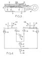
- Figures 2 and 3 show the construction of the lower jacks 11B.
- the cylinder 12 is provided adjacent one end with a peripheral flange 20 which locates the cylinder within a casing 21. At its other end the cylinder is closed by an end cap 22 ( Figure 3) through which extends the piston rod 13.
- the piston rod is of tubular form and has an internal wall or abutment 23.
- the end of the piston rod carries an eye 24 to form part of one of the couplings 13A whereby the piston rod is secured to the cowl 10.
- the piston rod 13 carries an annular piston 25 of larger diameter than the piston rod and the internal surface of the piston is recessed to accommodate a sleeve 26 having a screw thread formation 27 on its internal surface.
- a hollow pinion wheel 29 mounted within the casing by means of a pair of axially spaced bearing assemblies 28, is a hollow pinion wheel 29 formed integrally with a hollow shaft 30 which extends within the piston rod 13 towards the end cap 22.
- the pinion wheel 29 is provided with gear teeth which mesh with complementary teeth formed on a short shaft, of which the rotary axis is shown at 31A.
- One end of the shaft is coupled to the adjacent end of the aforementioned rotary flexible shaft.
- the hollow shaft 30 is provided on its outer peripheral surface with a screw thread formation 31 which is complementary with the thread formation 27 and forms therewith a reversible threaded connection for the purpose to be described.
- the piston 25 In operation, when the manifold 14 is connected to a source of fluid under pressure and the manifold 15 is connected to the same or a lower pressure, the piston 25 will move towards the right as seen in the drawings and the piston rod will extend from the cylinder to deploy the cowl 10. The extent of movement of the piston will be determined by its engagement with the end cap 22 or by an end stop associated with the cowl. Movement of the piston 25 in the case where the manifolds are connected to the same pressure is due to the fact that the effective end area of the piston exposed to the fluid pressure in the casing 21 is greater than the annular area of the piston within the cylinder 12. In order to retract the piston 25 and cowl, the manifold 14 is connected to a drain.
- the jacks 11A are similar in construction to the jacks 11B so far described without the locks and sensing units.
- the sensing unit 18 is housed within an extension 32 of the casing 21 and an end closure 33 and includes a pair of generally diametrically opposed electrical switches 34, 35 which are carried on the end closure 33 and which have opposing generally radially outwardly movable actuating elements 36, 37 respectively.
- the switches are mounted so that the axes of movement of the actuating elements are offset in the axial direction of the piston movement.
- the sensing unit further includes an actuating rod 38 which extends through the hollow shaft 30 for engagement with the abutment 23 defined by the piston rod. At its end remote from the switches, the rod 38 carries an abutment sleeve 39 of which the outer surface is guided by the internal surface of the piston rod 13.
- a portion 40 of the actuating rod 38 which lies within the extension 32 of the casing is of enlarged diameter and defines a thrust shoulder 41. Spaced from this shoulder in the direction towards the switches, is an annular groove in which is located an annular thrust member 42.
- the axial spacing between the thrust shoulder 41 and the opposing face of the thrust member 42 corresponds to the axial spacing between a pair of thrust faces defined respectively on flange portions 21A, 33A of the casing 21 and the end closure 33.
- Located adjacent the thrust faces are respective thrust rings 44 with a prestressed spring pack 45 disposed between them.
- the thrust rings 44 are in engagement with the aforesaid thrust faces and also with the thrust member 42 and thrust shoulder 41.
- the actuating rod 38 can therefore be said to be in an intermediate centralised position in which the actuating elements 36, 37 of the switches extend into a circumferential groove 46 formed in the actuating rod 38. It will be noted also that the remote end of the actuating rod is in engagement with the piston rod abutment 23. If it is assumed that the cowl is being moved to the stowed position, the piston 25 as shown, has not yet reached its fully retracted position because it is still spaced from an annular stop 47.
- the locking units 19 When it is required to deploy the cowl, the locking units 19 are unlocked and hydraulic fluid under pressure is supplied to the jack casings to cause movement of the pistons as described. This in turn causes the actuating rod 38 in each jack 11B to be moved by the spring pack 45 to the centralized position as shown in Figures 2 and 3 and the actuating elements 36 will move back into the groove 46.
- the cowl reaches the deployed position the thread formation 27 moving with the piston engages the abutment collar 39 and the final part of the piston movement into the deploy position moves the actuating rod 38 in the opposite direction to that described above.
- the spring pack is again further stressed and the actuating element 37 of each switch 35 associated with the jacks 11B is operated to provide a cowl deployed signal.
- the switches 34 remain inoperative at this time with their plungers 36 still in the grooves 46.
- Each switch 34 incorporates two pairs of contacts both of which are closed when the associated actuating element 36 is driven out of the respective grooves 46.
- Figure 4 shows a monitoring circuit for the two switches 34 on the jacks 11B and for convenience the two switches are referenced 34A, 34B.
- the pairs of contacts 50, 51 of the switch 34A provide connection when closed, from an electric current supply source to the input terminals respectively of a first AND gate 52 and to the input terminals of a first XOR gate 53.
- the pairs of contacts 54, 55 of the switch 34B are connected to a second AND gate 56 and a second XOR gate 57.
- the output terminals of the XOR gates are connected to the input terminals of an OR gate 58 having an output terminal 59.
- the output terminals of the AND gates 52, 56 are connected to the input terminals of the third AND gate 60 and also to the input terminals of a third XOR gate 61.
- the AND gate 60 has an output terminal 62 and the XOR gate 61 has an output terminal 63.
- the output of the XOR gate 53 will be at logic HIGH as also will be the output 59 of the OR gate 58. In this situation the output 62 will be at logic LOW and the output 63 at logic HIGH.
Landscapes
- Engineering & Computer Science (AREA)
- Chemical & Material Sciences (AREA)
- Combustion & Propulsion (AREA)
- Mechanical Engineering (AREA)
- General Engineering & Computer Science (AREA)
- Actuator (AREA)
Applications Claiming Priority (2)
| Application Number | Priority Date | Filing Date | Title |
|---|---|---|---|
| GB9607393 | 1996-04-09 | ||
| GBGB9607393.7A GB9607393D0 (en) | 1996-04-09 | 1996-04-09 | Actuating system |
Publications (2)
| Publication Number | Publication Date |
|---|---|
| EP0801220A2 true EP0801220A2 (de) | 1997-10-15 |
| EP0801220A3 EP0801220A3 (de) | 1998-11-04 |
Family
ID=10791793
Family Applications (1)
| Application Number | Title | Priority Date | Filing Date |
|---|---|---|---|
| EP97302404A Withdrawn EP0801220A3 (de) | 1996-04-09 | 1997-04-08 | Betätigungsvorrichtung für ein Schubumkehrsystem eines Flugzeugs |
Country Status (2)
| Country | Link |
|---|---|
| EP (1) | EP0801220A3 (de) |
| GB (1) | GB9607393D0 (de) |
Cited By (1)
| Publication number | Priority date | Publication date | Assignee | Title |
|---|---|---|---|---|
| EP3951155A1 (de) * | 2020-05-05 | 2022-02-09 | Rohr, Inc. | Betätigungssystem für einen schubumkehrer eines flugzeugantriebssystems |
Family Cites Families (4)
| Publication number | Priority date | Publication date | Assignee | Title |
|---|---|---|---|---|
| CH418841A (de) * | 1962-07-18 | 1966-08-15 | Festo Maschf Stoll G | Arbeitszylinder für pneumatische und hydraulische Arbeitsmedien |
| DD101469A1 (de) * | 1972-12-21 | 1973-11-12 | ||
| FR2377021A1 (fr) * | 1977-01-06 | 1978-08-04 | Outillage Air Comprime | Dispositif de detection de la position d'un piston |
| US4714006A (en) * | 1982-02-24 | 1987-12-22 | Pneumo Corporation | Fluid actuator with feedback mechanism |
-
1996
- 1996-04-09 GB GBGB9607393.7A patent/GB9607393D0/en active Pending
-
1997
- 1997-04-08 EP EP97302404A patent/EP0801220A3/de not_active Withdrawn
Cited By (2)
| Publication number | Priority date | Publication date | Assignee | Title |
|---|---|---|---|---|
| EP3951155A1 (de) * | 2020-05-05 | 2022-02-09 | Rohr, Inc. | Betätigungssystem für einen schubumkehrer eines flugzeugantriebssystems |
| US11781502B2 (en) | 2020-05-05 | 2023-10-10 | Rohr, Inc. | Actuation system for a thrust reverser of an aircraft propulsion system |
Also Published As
| Publication number | Publication date |
|---|---|
| GB9607393D0 (en) | 1996-06-12 |
| EP0801220A3 (de) | 1998-11-04 |
Similar Documents
| Publication | Publication Date | Title |
|---|---|---|
| EP0536954B1 (de) | Verriegelung einer Schubumkehrvorrichtung | |
| AU727557B2 (en) | Electric control system for a turbojet thrust reverser | |
| EP0801221A2 (de) | Betätigungssystem für eine Schubumkehrvorrichtung eines Flugzeugs | |
| US7174828B2 (en) | Linear actuator | |
| US8733080B2 (en) | Thrust reverser and VAFN arrangement | |
| US3003470A (en) | Actuator with variable position stroke limiter | |
| KR20150035812A (ko) | 블로 다운 액추에이터 조립체 | |
| CN102472112A (zh) | 用于例如推力反向器罩的可移动飞行器发动机舱元件的驱动系统 | |
| EP3480116B1 (de) | Elektromechanische aktuatorsysteme zum öffnen und schliessen von flugzeugtriebwerksverkleidungstüren | |
| US2811136A (en) | Lock mechanism for fluid motors | |
| US20130299631A1 (en) | Drive screw assembly and landing gear assembly with same | |
| US11255294B2 (en) | Thrust reverser velocity control valve | |
| US4841844A (en) | Fluid actuators with LVDT feedback mechanisms | |
| EP0801220A2 (de) | Betätigungsvorrichtung für ein Schubumkehrsystem eines Flugzeugs | |
| US6138449A (en) | Lock for a thrust reverser mechanism and a thrust reverser mechanism | |
| EP1552131B1 (de) | BETûTIGUNGSSYSTEM F R ELEKTROHYDRAULISCHE SCHUBUMKEHRVERRIEGELUNG | |
| US3133476A (en) | Rotary actuators | |
| US3515033A (en) | Actuators | |
| EP0087254B1 (de) | Druckmittelverbraucher mit Folgeventil | |
| CN110925262A (zh) | 一种双余度开锁作动装置 | |
| US3342111A (en) | Fluid pressure actuator and locking means | |
| US3442176A (en) | Actuator locking mechanism | |
| EP3004593B1 (de) | Triebwerk mit einem schubumkehrsperrmechanismus | |
| GB2408725A (en) | Thrust reverser actuation system | |
| EP1024300B1 (de) | Anordnung zum Einbau eines Sensors |
Legal Events
| Date | Code | Title | Description |
|---|---|---|---|
| PUAI | Public reference made under article 153(3) epc to a published international application that has entered the european phase |
Free format text: ORIGINAL CODE: 0009012 |
|
| AK | Designated contracting states |
Kind code of ref document: A2 Designated state(s): DE FR GB IT |
|
| RIN1 | Information on inventor provided before grant (corrected) |
Inventor name: HARVEY, JOHN HERBERT Inventor name: DAVIES, STEPHEN HARLOW |
|
| PUAL | Search report despatched |
Free format text: ORIGINAL CODE: 0009013 |
|
| AK | Designated contracting states |
Kind code of ref document: A3 Designated state(s): DE FR GB IT |
|
| RAP1 | Party data changed (applicant data changed or rights of an application transferred) |
Owner name: LUCAS INDUSTRIES LIMITED |
|
| STAA | Information on the status of an ep patent application or granted ep patent |
Free format text: STATUS: THE APPLICATION IS DEEMED TO BE WITHDRAWN |
|
| 18D | Application deemed to be withdrawn |
Effective date: 19990505 |