EP0801212A1 - Engine variable valve timing mechanism - Google Patents
Engine variable valve timing mechanism Download PDFInfo
- Publication number
- EP0801212A1 EP0801212A1 EP97105771A EP97105771A EP0801212A1 EP 0801212 A1 EP0801212 A1 EP 0801212A1 EP 97105771 A EP97105771 A EP 97105771A EP 97105771 A EP97105771 A EP 97105771A EP 0801212 A1 EP0801212 A1 EP 0801212A1
- Authority
- EP
- European Patent Office
- Prior art keywords
- rotor
- camshaft
- passage
- oil
- face
- Prior art date
- Legal status (The legal status is an assumption and is not a legal conclusion. Google has not performed a legal analysis and makes no representation as to the accuracy of the status listed.)
- Granted
Links
Images


Classifications
-
- F—MECHANICAL ENGINEERING; LIGHTING; HEATING; WEAPONS; BLASTING
- F01—MACHINES OR ENGINES IN GENERAL; ENGINE PLANTS IN GENERAL; STEAM ENGINES
- F01L—CYCLICALLY OPERATING VALVES FOR MACHINES OR ENGINES
- F01L1/00—Valve-gear or valve arrangements, e.g. lift-valve gear
- F01L1/34—Valve-gear or valve arrangements, e.g. lift-valve gear characterised by the provision of means for changing the timing of the valves without changing the duration of opening and without affecting the magnitude of the valve lift
- F01L1/344—Valve-gear or valve arrangements, e.g. lift-valve gear characterised by the provision of means for changing the timing of the valves without changing the duration of opening and without affecting the magnitude of the valve lift changing the angular relationship between crankshaft and camshaft, e.g. using helicoidal gear
- F01L1/3442—Valve-gear or valve arrangements, e.g. lift-valve gear characterised by the provision of means for changing the timing of the valves without changing the duration of opening and without affecting the magnitude of the valve lift changing the angular relationship between crankshaft and camshaft, e.g. using helicoidal gear using hydraulic chambers with variable volume to transmit the rotating force
-
- B—PERFORMING OPERATIONS; TRANSPORTING
- B21—MECHANICAL METAL-WORKING WITHOUT ESSENTIALLY REMOVING MATERIAL; PUNCHING METAL
- B21D—WORKING OR PROCESSING OF SHEET METAL OR METAL TUBES, RODS OR PROFILES WITHOUT ESSENTIALLY REMOVING MATERIAL; PUNCHING METAL
- B21D22/00—Shaping without cutting, by stamping, spinning, or deep-drawing
- B21D22/20—Deep-drawing
- B21D22/21—Deep-drawing without fixing the border of the blank
-
- B—PERFORMING OPERATIONS; TRANSPORTING
- B21—MECHANICAL METAL-WORKING WITHOUT ESSENTIALLY REMOVING MATERIAL; PUNCHING METAL
- B21K—MAKING FORGED OR PRESSED METAL PRODUCTS, e.g. HORSE-SHOES, RIVETS, BOLTS OR WHEELS
- B21K1/00—Making machine elements
- B21K1/20—Making machine elements valve parts
- B21K1/22—Making machine elements valve parts poppet valves, e.g. for internal-combustion engines
-
- B—PERFORMING OPERATIONS; TRANSPORTING
- B23—MACHINE TOOLS; METAL-WORKING NOT OTHERWISE PROVIDED FOR
- B23P—METAL-WORKING NOT OTHERWISE PROVIDED FOR; COMBINED OPERATIONS; UNIVERSAL MACHINE TOOLS
- B23P15/00—Making specific metal objects by operations not covered by a single other subclass or a group in this subclass
- B23P15/001—Making specific metal objects by operations not covered by a single other subclass or a group in this subclass valves or valve housings
- B23P15/002—Making specific metal objects by operations not covered by a single other subclass or a group in this subclass valves or valve housings poppet valves
-
- F—MECHANICAL ENGINEERING; LIGHTING; HEATING; WEAPONS; BLASTING
- F01—MACHINES OR ENGINES IN GENERAL; ENGINE PLANTS IN GENERAL; STEAM ENGINES
- F01L—CYCLICALLY OPERATING VALVES FOR MACHINES OR ENGINES
- F01L3/00—Lift-valve, i.e. cut-off apparatus with closure members having at least a component of their opening and closing motion perpendicular to the closing faces; Parts or accessories thereof
- F01L3/02—Selecting particular materials for valve-members or valve-seats; Valve-members or valve-seats composed of two or more materials
-
- F—MECHANICAL ENGINEERING; LIGHTING; HEATING; WEAPONS; BLASTING
- F01—MACHINES OR ENGINES IN GENERAL; ENGINE PLANTS IN GENERAL; STEAM ENGINES
- F01L—CYCLICALLY OPERATING VALVES FOR MACHINES OR ENGINES
- F01L3/00—Lift-valve, i.e. cut-off apparatus with closure members having at least a component of their opening and closing motion perpendicular to the closing faces; Parts or accessories thereof
- F01L3/12—Cooling of valves
- F01L3/14—Cooling of valves by means of a liquid or solid coolant, e.g. sodium, in a closed chamber in a valve
-
- F—MECHANICAL ENGINEERING; LIGHTING; HEATING; WEAPONS; BLASTING
- F01—MACHINES OR ENGINES IN GENERAL; ENGINE PLANTS IN GENERAL; STEAM ENGINES
- F01L—CYCLICALLY OPERATING VALVES FOR MACHINES OR ENGINES
- F01L3/00—Lift-valve, i.e. cut-off apparatus with closure members having at least a component of their opening and closing motion perpendicular to the closing faces; Parts or accessories thereof
- F01L3/20—Shapes or constructions of valve members, not provided for in preceding subgroups of this group
-
- F—MECHANICAL ENGINEERING; LIGHTING; HEATING; WEAPONS; BLASTING
- F16—ENGINEERING ELEMENTS AND UNITS; GENERAL MEASURES FOR PRODUCING AND MAINTAINING EFFECTIVE FUNCTIONING OF MACHINES OR INSTALLATIONS; THERMAL INSULATION IN GENERAL
- F16D—COUPLINGS FOR TRANSMITTING ROTATION; CLUTCHES; BRAKES
- F16D3/00—Yielding couplings, i.e. with means permitting movement between the connected parts during the drive
- F16D3/02—Yielding couplings, i.e. with means permitting movement between the connected parts during the drive adapted to specific functions
- F16D3/10—Couplings with means for varying the angular relationship of two coaxial shafts during motion
-
- F—MECHANICAL ENGINEERING; LIGHTING; HEATING; WEAPONS; BLASTING
- F01—MACHINES OR ENGINES IN GENERAL; ENGINE PLANTS IN GENERAL; STEAM ENGINES
- F01L—CYCLICALLY OPERATING VALVES FOR MACHINES OR ENGINES
- F01L1/00—Valve-gear or valve arrangements, e.g. lift-valve gear
- F01L1/34—Valve-gear or valve arrangements, e.g. lift-valve gear characterised by the provision of means for changing the timing of the valves without changing the duration of opening and without affecting the magnitude of the valve lift
- F01L1/344—Valve-gear or valve arrangements, e.g. lift-valve gear characterised by the provision of means for changing the timing of the valves without changing the duration of opening and without affecting the magnitude of the valve lift changing the angular relationship between crankshaft and camshaft, e.g. using helicoidal gear
- F01L1/3442—Valve-gear or valve arrangements, e.g. lift-valve gear characterised by the provision of means for changing the timing of the valves without changing the duration of opening and without affecting the magnitude of the valve lift changing the angular relationship between crankshaft and camshaft, e.g. using helicoidal gear using hydraulic chambers with variable volume to transmit the rotating force
- F01L2001/34423—Details relating to the hydraulic feeding circuit
- F01L2001/34426—Oil control valves
Definitions
- the present invention relates to a variable valve timing mechanism provided in an engine to change the valve timing of intake valves or exhaust valves. More particularly, the present invention pertains to a variable valve timing mechanism that is driven by fluid pressure.
- VVT variable valve timing mechanism
- An engine to displace the rotational phase of a camshaft and adjust the valve timing of either an intake valve or an exhaust valve.
- the operation of the VVT optimizes the valve timing in accordance with the operating state of the engine (engine load, engine speed, and other factors). This improves fuel economy, increases engine power, and suppresses undesirable engine emissions regardless of different operating states of the engine.
- VVT variable valve timing mechanism
- Japanese Unexamined Patent Publication No. Hei 5-113112 discloses an example of vane type VVT.
- a rotor is rotated relative to a pulley. Oil pressure is used to change the rotational phase of the camshaft with respect to the pulley, and thus the valve timing of valves driven by the camshaft is adjusted.
- This vane type VVT permit the axial length of the camshaft to be reduced as compared with an engine using a helical gear type VVT.
- vane type VVTs have a structure as shown in Figure 12 and 13.
- the VVT 80 is attached to the distal end of a camshaft 84.
- the camshaft 84 has a bolt hole 841 defined on the distal end, and a rotor 82 is fixed to that end by a bolt 85.
- a sprocket 81 surrounds the rotor 82 such that it can rotate relative to the rotor 82 and the camshaft 84.
- the sprocket 81 is connected to a crankshaft (not shown) by a chain (not shown).
- the sprocket 81 has a plurality of inward protrusions 811, and every adjacent two protrusions 811 define a recess 812.
- the rotor 82 has a plurality of vanes 821, and each vane 821 is housed in one of the recesses 812.
- Each vane 821 defines on each side a first hydraulic chamber 831 and a second hydraulic chamber 832 in the corresponding recess 812.
- the camshaft 84 receives a torque from the VVT 80 at its distal end.
- the camshaft 84 contains many hollow spaces including the oil passages 842, 843 and the bolt hole 841, the camshaft 84 tends to have insufficient rigidity against the torque.
- the camshaft 84 has a smaller diameter at the journal 844 than at other portions, the rigidity of the journal 844 is lower than that of the other portions.
- the oil passages 842, 843 open on the same plane, i.e., on the end face 86 of the camshaft 84, and the openings of these oil passages 842, 843 are close to one another. Accordingly, it is difficult to seal between the oil passage 842 and the oil passage 843, and the oil supplied to the oil passages 842 can leak into the oil passages 843 or, the oil supplied to the oil passages 843 can leak to the oil passages 842. If leakage occurs, the desired oil pressure values are not attained in the hydraulic chambers 831, 832, which deteriorates the response of the VVT 80.
- the present invention was accomplished in view of such circumstances described above, and it is an objective of the invention to provide a variable valve timing mechanism, which is driven by hydraulic fluid pressure, more specifically, a variable valve timing mechanism for an engine, which employs a camshaft having improved rigidity and which can reduce leakage of hydraulic fluid supplied to the respective pressure chambers.
- apparatus includes a camshaft for driving the intake valves or the exhaust valves, the camshaft having a distal end face, a first rotor fixed to the distal end face of the camshaft, the first rotor having vanes protruding radially outward, a second rotor disposed to surround the first rotor to be rotatable relative to the first rotor; the second rotor having recesses on the inner circumference, each recess being divided by the vane into a first pressure chamber and a second pressure chamber, a first passage defined in the camshaft, for supplying a fluid pressure to the first pressure chamber so as to change the rotational phase of the second rotor with respect to the camshaft, the first passage having an opening at the distal end face of the camshaft, and a second passage defined in the camshaft, for supplying a fluid pressure to the second pressure chamber so as to change the rotational phase of the second rotor with respect to the camshaft, the second passage having an
- variable valve timing mechanism (hereinafter referred to as VVT) according to a first embodiment of the present invention will be described below referring to Figures 1 to 3.
- an intake side camshaft 14 and a exhaust side camshaft 70 are supported rotatably on a cylinder head 79.
- the terms “left” and “right” are used herein to refer to the leftward and rightward direction of Fig. 1.
- the terms “clockwise” and “counterclockwise” refer to the perspective of Fig. 2.
- the camshafts 14,70 each have a plurality of cams 75.
- An intake valve 77 is located under each cam 75 of the camshaft 14, whereas an exhaust valve 78 is located under each cam 75 of the camshaft 70.
- a VVT 10 is attached to the end of the intake side camshaft 14.
- a drive gear 74 which is attached to the left end of the exhaust camshaft 70 is meshed with a driven gear 13 attached to the distal end portion of the intake side camshaft 14.
- a pulley 71 is attached to the right end of the exhaust camshaft 70 and is connected to a pulley 76 of a crankshaft 73 via a timing belt 72.
- the exhaust camshaft 70 When the crankshaft 73 is rotated, the exhaust camshaft 70 is rotated via the pulleys 76,71 and the belt 72. The torque of the exhaust camshaft 70 is transmitted to the intake camshaft 14 via the gears 74, 13 to rotate the camshaft 14. Thus, the intake valves 77 and the exhaust valves 78 are opened and closed under predetermined valve timings by the rotation of these camshafts 14 and 70.
- the VVT 10 contains the camshaft 14, a rotor 11 fixed to the left end of the camshaft 14, a housing 12 surrounding the rotor 11, the driven gear 13 fixed to the housing 12 and a cover 15 covering the housing 12.
- the camshaft 14 has a journal 141, and the camshaft 14 is supported at the journal 141 by the cylinder head 79 and a bearing cap 67.
- the camshaft 14 has a bolt hole 143 at the left end.
- the rotor 11 and the cover 15 are fixed to the left end of the camshaft 14 by a bolt 30 and are rotated integrally with the camshaft 14.
- the housing 12 surrounds the rotor 11 and is rotatable relative to the camshaft 14 and the rotor 11.
- the cover 15 has a flange 151 covering the housing 12.
- the driven gear 13 is fixed to one side of the housing 12 by bolts 31 to be rotatable relative to the camshaft 14 and the rotor 11.
- the driven gear 13 has a thick ring-like shape and has a plurality of teeth 132 formed on the circumference.
- the driven gear 13 is rotatably supported on outer surface 149 of the camshaft 14.
- the housing 12 and the rotor 11 are rotated clockwise.
- the housing 12 and that of the rotor 11 shown in Figure 2 are in their initial positions where the valve timing of the intake valves 77 (shown in Figure 1) is delayed most.
- the housing 12 has four inward protrusions 121, and every adjacent two protrusions 121 define a recess 122.
- the driven gear 13 is fixed by the bolts 31 to the protrusions 121 of the housing 12.
- the rotor 11 consists of a boss 48 and four vanes 112 protruding therefrom radially outward.
- the outer circumference of the boss 48 is brought into contact with the end faces of the protrusions 121.
- These four vanes 112 are arranged at approximately 90 degree intervals, and the vanes 112 are housed in the recesses 112 of the housing 12 respectively.
- Each vane 112 defines, in the corresponding recess 122, a first hydraulic chamber 101 and a second hydraulic chamber 102.
- the first hydraulic chamber 101 is located on the trailing side with respect to the rotating direction of the vane 112, while the second hydraulic chamber 102 is located on the leading side.
- Oil pressure is supplied to the hydraulic chambers 101, 102 respectively so as to effect relative rotation of the rotor 11 with respect to the housing 12.
- a seal 123 and a leaf spring 124 for urging the seal 123 toward the inner circumference of the housing 12 are attached to the distal end of each vane 112. The seal 123 and the leaf spring 124 seal between the first hydraulic chamber 101 and the second hydraulic chamber 102.
- two oil passages 145, 147 are defined in the camshaft 14 in the axial direction.
- two oil passages 36, 37 are defined in the cylinder head 79.
- Ring-like oil grooves 18, 19 are formed on the inner surfaces of the cylinder head 79 and the bearing cap 67.
- An oil hole 144, which is defined in the camshaft 14, connects the oil passage 145 and the oil groove 36; while another oil hole 146, which is also defined in the camshaft 14, connects the oil passage 147 and the oil groove 19.
- An annular chamber 114 is defined around the left end portion of the camshaft 14.
- the boss 48 of the rotor 11 has four passages 115 defined radially therein, and each passage 115 secures communication between the annular chamber 114 and the first hydraulic chambers 101 ( Figure 2).
- the camshaft 14 has a ring-like oil groove 142 formed on its outer surface 149. Another oil hole 148, which is also defined in the camshaft 14, connects the oil passage 147 and the oil groove 142.
- the driven gear 13 contains four passages 134 defined radially therein, and these passages 134 connects the oil groove 142 and the second hydraulic chambers 102 ( Figure 2). Oil is supplied to the first hydraulic chambers 101 through the oil passage 36, the oil groove 18, the oil hole 144, the oil passage 145, the annular chamber 114 and the passages 115. Meanwhile, oil is supplied to the second hydraulic chambers 102 through the oil passage 37, the oil groove 19, the oil hole 146, the oil passage 147, the oil hole 148, the oil groove 142 and the passages 134.
- the camshaft 14 has some hollow spaces therein, only the oil passage 145 and the bolt hole 143 open to the left end face of the camshaft 14, and the oil groove 142 opens to the outer surface 149 of the camshaft 14.
- a small clearance for permitting relative rotation between the camshaft 14 and the driven gear 13 is defined between the outer surface 149 of the camshaft 14 and the inner surface 133 of the driven gear 13.
- an oil control valve (hereinafter referred to as an OCV) 40 for supplying oil pressure to the first and second hydraulic chambers 101, 102 and of the VVT 10 will be described.
- the OCV 40 has a plurality of ports 45a, 45b, 45r, 45t to switch the direction of supplying and discharging the oil and to adjust the oil pressure supplied from the first port 45a and the second port 45b to the hydraulic chambers 101 and 102, respectively.
- the OCV 40 is provided with a solenoid actuator 41, a casing 45, a spool 44 disposed in the casing 45, a plunger 43 connected to the spool 44 and a coil spring 42 for urging the spool 44.
- the spool 44 is reciprocated in the axial direction by performing duty control of the actuator 41. This reciprocating motion of the spool 44 achieves adjustment of the amount of oil to be supplied.
- the supply port 45t is connected via a hydraulic pump 46 to an oil pan 47; while the first and the second ports 45a and 45b are connected to the oil passages 36 and 37 respectively.
- the drain port 45r is connected to the oil pan 47.
- the spool 44 is cylindrical valve body and has lands 44a, which interrupt the flow of the oil and passages 44b, 44c, which permit flow of the oil.
- the oil drawn or discharged by the pump 46 under the operation of the OCV 40 is supplied through the supply port 45t and the first port 45a to the oil passage 36 or through the supply port 45t and the second port 45b to the oil passage 37.
- the oil is supplied to the first hydraulic chambers 101 to increase the oil pressure in each hydraulic chamber 101.
- the oil in each second hydraulic chamber 102 is discharged through the oil passage 37 to the second port 45b to reduce the oil pressure in the second hydraulic chamber 102.
- the oil pressure in each second hydraulic chamber 102 is increased.
- the oil in each first hydraulic chamber 101 is discharged through the oil passage 36 to the first port 45a to reduce the oil pressure in the first hydraulic chamber 101.
- Introduction of the oil through the ports 45a, 45b or discharge of the oil through these ports 45a, 45b is interrupted by blocking them.
- the oil supplied to the oil groove 142 of the camshaft 14 is fed to the small clearance between the outer surface 149 of the camshaft 14 and the inner surface 133 of the driven gear 13 to facilitate smooth relative rotation of the camshaft 14 relative to the driven gear 13.
- valve timing of the intake valves 77 can be changed to the most delayed angle phase or to the most advanced angle phase by performing binary adjustment of the oil pressure values in the hydraulic chambers 101, 102 respectively under control of the OCV 40. Otherwise, the valve timing of the intake valves 77 may be changed continuously between the most delayed angle phase and the most advanced angle phase by continuously adjusting the oil pressure values in the hydraulic chambers 101, 102.
- the camshaft 14 of the first embodiment has less hollow space formed at the left end, so that the rigidity of the camshaft 14 is improved.
- the distance between the passage 115 opening to each first hydraulic chamber 101 and the passage 134 opening to each second hydraulic chamber 102 is increased compared with that of the prior art VVT. Accordingly, leakage of oil from the passages 134 to the first hydraulic chambers 101 or from the passages 115 to the second hydraulic chambers 102 is reduced, which reduces oil pressure interference between the hydraulic chambers 101 and 102. Thus, a desired oil pressure can be supplied to the hydraulic chambers 101 and 102, and the responsiveness of the VVT 10 is improved.
- the outside diameter ⁇ B at the distal end portion of a camshaft 14 is designed to be smaller than the outside diameter ⁇ A of the boss 38 of the rotor 11.
- the boundary between the outer circumference 149 of the camshaft 14 and the inner circumference 133 of the driven gear 13 is sealed by one side of the boss 38. Accordingly, that boundary is not exposed to the first and the second hydraulic chambers 101, 102 ( Figure 4).
- a small clearance permitting relative rotation between the camshaft 14 and the driven gear 13 is defined between the outer surface 149 of the camshaft 14 and the inner surface 133 of the driven gear 13. Smooth rotation of the camshaft 14 relative to the driven gear 13 is achieved by the oil supplied to the clearance.
- an intake side camshaft 25 the exhaust camshaft 70 and the crankshaft 73 are connected by a chain 29 to which a predetermined tension is applied by idlers 58, 59.
- the VVT 20 according to the third embodiment is attached to the left end of the intake side camshaft 25.
- the camshafts 25, 70 are rotated synchronously with the crankshaft 73 via the chain 29 and the sprockets 49, 21, 57, and the intake valves 77 and the exhaust valves 78 are driven under predetermined valve timings, respectively.
- the VVT 20 includes a rotor 22, a housing 24 surrounding the rotor 22, a sprocket 21 fixed to the housing 24 via a plate 23, and a cover 26 covering the housing 24.
- the camshaft 25 supported on the cylinder head 79 has a bolt hole 253 defined on the left end.
- the rotor 22 is fixed to that end of the camshaft 25 by a bolt 32 so that it is rotated integrally with the camshaft 25.
- the housing 24 surrounding the rotor 22 is rotatable relative to the camshaft 25 and the rotor 22.
- the cover 26, the plate 23 and the sprocket 21 are fixed by bolts 33 to the housing 24 so that they are rotated integrally.
- the rotor 22 has a boss 27 and four vanes 222, each of which defines a first hydraulic chamber 101 and a second hydraulic chamber 102 in a corresponding recess 242 of the housing 24.
- An annular chamber 221 is defined between the left end portion of the camshaft 25 and the rotor 22.
- the boss 27 of the rotor 22 has four passages 225 defined radially therein, and these passages 225 connect between the annular chamber 221 and the first hydraulic chambers 101.
- the diameter ⁇ A of the boss 27 of the rotor 22 is designed to be greater than the diameter ⁇ B at the left end portion of the camshaft 25.
- the boundary between the outer circumference 231 of the camshaft 25 and the inner circumference 211 of the plate 23 is sealed by the boss 27.
- the camshaft 25 contains an oil passage 255 defined axially therein, and the oil passage 255 opens at the left end to the annular chamber 221 and at the right to the oil hole 254.
- An annular chamber 213 is defined between the sprocket 21 and the plate 23 to connect an oil groove 252 formed on the outer circumference of the camshaft 25 with the oil holes 232.
- the camshaft 25 contains an oil passage 258 extending diagonally to connect the oil groove 252 and the bolt hole 253.
- the camshaft 25 has a radial oil passage 256 defined at the journal 251 thereof so as to communicate with the bolt hole 253.
- the clearance between the outer surface 231 of the camshaft 25 and the inner surface of the plate 23 is sealed by the boss 27 at the left end face of the camshaft 25, so that leakage of the oil from the clearance is substantially avoided. Accordingly, the desired oil pressure is supplied to the chambers 101 and 102 respectively, and the responsiveness and operability of the VVT 20 is improved.
- the distance between the passage 225 opening to the first hydraulic chamber 101 and the oil hole 232 opening to the second hydraulic chamber 102 is increased compared with that in the prior art VVT. Accordingly, oil leakage between the passage 225 and the oil hole 232 is substantially reduced, which results in more accurate operation of the VVT 20.
- the diameter of the housing 24 can be increased by increasing the diameter of the plate 23 without increasing the diameter of the sprocket 21.
- the force to be applied to each vane 22 can be increased. Accordingly, the driving force of the VVT 20 is increased while vibration of the rotor 22 attributed to fluctuation in the torque of the camshaft 25 is reduced. Thus, the responsiveness of the VVT 20 is improved.
- VVT according to a fourth embodiment of the present invention will be described below referring to Figures 9 and 10. Differences from the third embodiment will primarily be described.
- the VVT of the fourth embodiment is applied to the same valve train as shown in Figure 6.
- the VVT 50 is provided with a lock pin 60 on one of four vanes 522.
- the lock pin 60 locks a rotor 52 relative to a sprocket 51 so as to retain the rotor 52 at the initial position of Fig. 10.
- Each passage 525 is defined in the rotor 52 to connect the annular chamber 221 to each of the first hydraulic chambers 101.
- One passage 525 opens to the first hydraulic chamber 101 and also to a releasing chamber 67 (to be described later).
- the lock pin 60 is housed in a lock pin hole 523.
- the lock pin 60 has a cylindrical shape and has a large diameter portion 61 and a small diameter portion 62.
- the lock pin 60 is urged by a spring 64, which urges the lock pin 60 toward a plate 53.
- the lock pin 60 has a first pressure receiving face 65, between the large diameter portion 61 and the small diameter portion 62, and a second pressure receiving face 66, which is at the end of the small diameter portion 62.
- the first pressure receiving surface 65 receives pressure from the oil supplied to the first hydraulic chambers 101, whereas the second pressure receiving surface 66 receives pressure from the oil supplied to the second hydraulic chambers 102.
- the lock pin 60 defines an annular releasing chamber 67, and the first pressure receiving surface 65 is opposed to the releasing chamber 67. Oil pressure is supplied through the passage 525 to the releasing chamber 67.
- the plate 53 contains a circular engaging hole 533 with which the lock pin 60 can engage.
- the second pressure receiving surface 66 of the lock pin 60 is opposed to the engaging hole 533.
- An annular chamber 534 is defined between the right side of the plate 53 and the left end of a camshaft 55.
- the annular chamber 534 communicates with each of second hydraulic chambers 102 via oil holes 532 and also with the engaging hole 533.
- An oil passage 558, communicating with the annular chamber 543, is defined in the camshaft 55, and this oil passage 558 is connected to the OCV 40 via another oil passage (not shown) defined in the camshaft 55.
- the rotor 52 When the engine is started, the rotor 52 is rotated integrally with the sprocket 51. Oil is gradually supplied to the hydraulic chambers 101, 102, and the oil pressure in the hydraulic chambers 101, 102 is unstable until they are filled. Meanwhile, the rotor 52 is subject to fluctuation in the torque of the camshaft 55. However, in the forth embodiment, since the movement of the rotor 52 is restricted by the lock pin 60, backlash of the rotor 52 is inhibited.
- the inner surface of the plate 53 which has the engaging hole 533 defined formed therein.
- the inner surface of the plate 53 is surface hardened.
- boron steel subjected to induction hardening, Cr steel or Cr-Mn steel subjected to hardening and tempering treatment and carburizing treatment may be suitably employed.
- Oil is supplied to the releasing chamber 67 or the engagement hole 533, although the pressure thereof is low when the engine is initially started. Accordingly, the lock pin 60 receives the pressure from oil at the first pressure receiving surface 65 or the second pressure receiving surface 66, and when the oil pressure is high enough, the lock pin 60 is disengaged from the engaging hole 533 against the urging force of the spring 64. Thus, after the oil pressure reaches a certain level, the engagement of the lock pin 60 with the engaging hole 533 is released to permit the rotor 52 to rotate relative to the sprocket 51. Once a sufficient oil pressure is reached, the lock pin 60 is maintained in the disengaged state until the engine is stopped.
- the rotor 52 and the camshaft 55 are rotated relative to the sprocket 51 by supplying oil to either the first hydraulic chambers 101 or the second hydraulic chambers 102 (with the pin 60 retracted), and thus the valve timing of the valves 77 ( Figure 6) driven by the camshaft 55 can be changed.
- the VVT 50 is provided with a surface-hardened plate 53, damage to the plate 53 is prevented even if the lock pin 60 are frequently brought into contact with the inner surface of the plate 53.
- the sprocket 51, the housing 54 and the plate 53 are fixed by a bolt 34.
- the plates 23 and 53 in the third embodiment and the fourth embodiment may be omitted.
- an annular chamber 69 can be formed as shown.
- valve timing of the intake valves 77 is changed, it is also possible to change the valve timing of the exhaust valves by attaching the VVT to the exhaust side camshaft.
- the pulley 71 can be connected to the right end of the intake camshaft 14, and the pulley 71 can be connected to the pulley 76 of the crankshaft 73 by the belt 72.
- the intake camshaft 14 is rotated synchronously with the crankshaft 73.
- the rotational phase of the exhaust side camshaft can be changed 70 relative to the crankshaft 73.
- a variable valve timing mechanism is provided at the distal end of a camshaft (14; 25; 39; 55) for changing a valve timing of an engine valve (77).
- a rotor (11; 22; 52) is fixed to the distal end face of the camshaft (14; 25; 39; 55), and the rotor has four vanes (112; 222; 522) protruding radially outward.
- a housing (12; 24; 54) is disposed to surround the rotor (11; 22; 52) to be rotatable relative to the rotor (11; 22; 52) and the camshaft (14; 25; 39; 55), and the housing (12; 24; 54) has recesses (122; 242; 542) on the inner circumference.
- Each recess (122; 242; 542) is divided by the vane (112; 222; 522) into a first pressure chamber (101) and a second pressure chamber (102).
- a first passage (145; 255; 555) is defined in the camshaft (14; 25; 39; 55), for supplying a hydraulic fluid pressure to the first pressure chamber (101) so as to change the rotational phase of the second rotor (12, 13; 21, 23, 24; 51, 53, 54) with respect to the camshaft (14; 25; 39; 55), and the first passage (145; 255; 555) has an opening at the distal end face of the camshaft (14; 25; 39; 55).
- a second passage (148; 258; 558) is defined in the camshaft (14; 25; 39; 55), for supplying a fluid pressure to the second pressure chamber (102) so as to change the rotational phase of the second rotor (12, 13; 21, 23, 24; 51, 53, 54) with respect to the camshaft (14; 25; 39; 55), and the second passage (148; 258; 558) has an opening at outer circumference (149; 231) of the camshaft (14; 25; 39; 55).
Abstract
Description
- The present invention relates to a variable valve timing mechanism provided in an engine to change the valve timing of intake valves or exhaust valves. More particularly, the present invention pertains to a variable valve timing mechanism that is driven by fluid pressure.
- A variable valve timing mechanism (hereafter referred to as VVT) is provided in an engine to displace the rotational phase of a camshaft and adjust the valve timing of either an intake valve or an exhaust valve. The operation of the VVT optimizes the valve timing in accordance with the operating state of the engine (engine load, engine speed, and other factors). This improves fuel economy, increases engine power, and suppresses undesirable engine emissions regardless of different operating states of the engine.
- U.S. Patent No. 5,483,930, which is incorporated herein by reference, discloses this a type of variable valve timing mechanism (hereinafter referred to as VVT) for an internal combustion engine. This VVT is of the helical gear type. In this VVT, the rotational phase of a camshaft with respect to a pulley is changed by moving a ring gear including a helical spline so as to adjust the valve timing of valves driven by the camshaft.
- Meanwhile, Japanese Unexamined Patent Publication No. Hei 5-113112 discloses an example of vane type VVT. In this vane type VVT, a rotor is rotated relative to a pulley. Oil pressure is used to change the rotational phase of the camshaft with respect to the pulley, and thus the valve timing of valves driven by the camshaft is adjusted. This vane type VVT permit the axial length of the camshaft to be reduced as compared with an engine using a helical gear type VVT.
- Generally, vane type VVTs have a structure as shown in Figure 12 and 13. As shown in Figure 12, the VVT 80 is attached to the distal end of a
camshaft 84. Thecamshaft 84 has abolt hole 841 defined on the distal end, and arotor 82 is fixed to that end by abolt 85. Asprocket 81 surrounds therotor 82 such that it can rotate relative to therotor 82 and thecamshaft 84. Thesprocket 81 is connected to a crankshaft (not shown) by a chain (not shown). - As shown in Figure 13, the
sprocket 81 has a plurality ofinward protrusions 811, and every adjacent twoprotrusions 811 define arecess 812. Therotor 82 has a plurality ofvanes 821, and eachvane 821 is housed in one of therecesses 812. Eachvane 821 defines on each side a firsthydraulic chamber 831 and a secondhydraulic chamber 832 in thecorresponding recess 812. - When oil pressure is supplied through
oil passages 842 defined through thecamshaft 84 into the firsthydraulic chambers 831, therotor 82 is rotated clockwise relative to thesprocket 81. When oil pressure is supplied throughoil passages 843 defined through thecamshaft 84 into the secondhydraulic chambers 832, therotor 82 is rotated counterclockwise relative to thesprocket 81. With the relative rotation of therotor 82, the rotational phase of thecamshaft 84 with respect to the sprocket 81 (crankshaft) is changed, and thus the valve timing of valves (not shown) to be driven by thecamshaft 84 is adjusted. - During operation of the VVT 80, the
camshaft 84 receives a torque from the VVT 80 at its distal end. However, since thecamshaft 84 contains many hollow spaces including theoil passages bolt hole 841, thecamshaft 84 tends to have insufficient rigidity against the torque. Particularly, since thecamshaft 84 has a smaller diameter at thejournal 844 than at other portions, the rigidity of thejournal 844 is lower than that of the other portions. - The
oil passages end face 86 of thecamshaft 84, and the openings of theseoil passages oil passage 842 and theoil passage 843, and the oil supplied to theoil passages 842 can leak into theoil passages 843 or, the oil supplied to theoil passages 843 can leak to theoil passages 842. If leakage occurs, the desired oil pressure values are not attained in thehydraulic chambers VVT 80. - The present invention was accomplished in view of such circumstances described above, and it is an objective of the invention to provide a variable valve timing mechanism, which is driven by hydraulic fluid pressure, more specifically, a variable valve timing mechanism for an engine, which employs a camshaft having improved rigidity and which can reduce leakage of hydraulic fluid supplied to the respective pressure chambers.
- To achieve the above objective, apparatus includes a camshaft for driving the intake valves or the exhaust valves, the camshaft having a distal end face, a first rotor fixed to the distal end face of the camshaft, the first rotor having vanes protruding radially outward, a second rotor disposed to surround the first rotor to be rotatable relative to the first rotor; the second rotor having recesses on the inner circumference, each recess being divided by the vane into a first pressure chamber and a second pressure chamber, a first passage defined in the camshaft, for supplying a fluid pressure to the first pressure chamber so as to change the rotational phase of the second rotor with respect to the camshaft, the first passage having an opening at the distal end face of the camshaft, and a second passage defined in the camshaft, for supplying a fluid pressure to the second pressure chamber so as to change the rotational phase of the second rotor with respect to the camshaft, the second passage having an opening at a face other than the distal end face.
- Other aspects and advantages of the invention will become apparent from the following description, taken in conjunction with the accompanying drawings, illustrating by way of example the principals of the invention.
- The invention, together with objects and advantages thereof, may best be understood by reference to the following description of the presently preferred embodiments together with the accompanying drawings.
- Figure 1 shows a diagrammatic plan view of a valve train including the variable timing mechanism (VVT) according to the present invention;
- Figure 2 shows a cross-sectional view of the VVT according to a first embodiment of the present invention;
- Figure 3 shows a cross-sectional view taken along the line 3-3 of Figure 2;
- Figure 4 shows a cross-sectional view of the VVT according to a second embodiment of the present invention;
- Figure 5 shows a cross-sectional view taken along the line 5-5 of Figure 4;
- Figure 6 shows a diagrammatic front view of an engine containing the VVT according to a third embodiment of the present invention;
- Figure 7 shows a cross-sectional view of the VVT shown in Figure 6 taken along the line 7-7 of Fig. 8;
- Figure 8 shows a cross-sectional view taken along the line 8-8 of Figure 7;
- Figure 9 shows a cross-sectional view of the VVT according to a fourth embodiment of the present invention taken along line 9-9 of Fig. 10;
- Figure 10 shows a cross-sectional view taken along the line 10-10 of Figure 9;
- Figure 11 shows a cross-sectional view of the VVT according to a fifth embodiment of the present invention;
- Figure 12 shows a cross-sectional view of the prior art VVT; and
- Figure 13 shows a cross-sectional view taken along the line 13-13 of Figure 12.
- The variable valve timing mechanism (hereinafter referred to as VVT) according to a first embodiment of the present invention will be described below referring to Figures 1 to 3.
- As shown in Figure 1, an
intake side camshaft 14 and aexhaust side camshaft 70 are supported rotatably on acylinder head 79. The terms "left" and "right" are used herein to refer to the leftward and rightward direction of Fig. 1. Similarly, the terms "clockwise" and "counterclockwise" refer to the perspective of Fig. 2. - The
camshafts cams 75. Anintake valve 77 is located under eachcam 75 of thecamshaft 14, whereas anexhaust valve 78 is located under eachcam 75 of thecamshaft 70. A VVT 10 is attached to the end of theintake side camshaft 14. Adrive gear 74, which is attached to the left end of theexhaust camshaft 70 is meshed with a drivengear 13 attached to the distal end portion of theintake side camshaft 14. Apulley 71 is attached to the right end of theexhaust camshaft 70 and is connected to a pulley 76 of acrankshaft 73 via atiming belt 72. - When the
crankshaft 73 is rotated, theexhaust camshaft 70 is rotated via thepulleys 76,71 and thebelt 72. The torque of theexhaust camshaft 70 is transmitted to theintake camshaft 14 via thegears camshaft 14. Thus, theintake valves 77 and theexhaust valves 78 are opened and closed under predetermined valve timings by the rotation of thesecamshafts - As shown in Figure 3, the VVT 10 contains the
camshaft 14, arotor 11 fixed to the left end of thecamshaft 14, ahousing 12 surrounding therotor 11, the drivengear 13 fixed to thehousing 12 and acover 15 covering thehousing 12. - The
camshaft 14 has ajournal 141, and thecamshaft 14 is supported at thejournal 141 by thecylinder head 79 and abearing cap 67. Thecamshaft 14 has abolt hole 143 at the left end. Therotor 11 and thecover 15 are fixed to the left end of thecamshaft 14 by abolt 30 and are rotated integrally with thecamshaft 14. Thehousing 12 surrounds therotor 11 and is rotatable relative to thecamshaft 14 and therotor 11. Thecover 15 has aflange 151 covering thehousing 12. - The driven
gear 13 is fixed to one side of thehousing 12 bybolts 31 to be rotatable relative to thecamshaft 14 and therotor 11. The drivengear 13 has a thick ring-like shape and has a plurality ofteeth 132 formed on the circumference. The drivengear 13 is rotatably supported onouter surface 149 of thecamshaft 14. - As shown in Figure 2, the
housing 12 and therotor 11 are rotated clockwise. Thehousing 12 and that of therotor 11 shown in Figure 2 are in their initial positions where the valve timing of the intake valves 77 (shown in Figure 1) is delayed most. Thehousing 12 has fourinward protrusions 121, and every adjacent twoprotrusions 121 define arecess 122. The drivengear 13 is fixed by thebolts 31 to theprotrusions 121 of thehousing 12. - The
rotor 11 consists of aboss 48 and fourvanes 112 protruding therefrom radially outward. The outer circumference of theboss 48 is brought into contact with the end faces of theprotrusions 121. These fourvanes 112 are arranged at approximately 90 degree intervals, and thevanes 112 are housed in therecesses 112 of thehousing 12 respectively. Eachvane 112 defines, in thecorresponding recess 122, a firsthydraulic chamber 101 and a secondhydraulic chamber 102. The firsthydraulic chamber 101 is located on the trailing side with respect to the rotating direction of thevane 112, while the secondhydraulic chamber 102 is located on the leading side. Oil pressure is supplied to thehydraulic chambers rotor 11 with respect to thehousing 12. Aseal 123 and aleaf spring 124 for urging theseal 123 toward the inner circumference of thehousing 12 are attached to the distal end of eachvane 112. Theseal 123 and theleaf spring 124 seal between the firsthydraulic chamber 101 and the secondhydraulic chamber 102. - Next, a structure for supplying oil pressure to the first and second
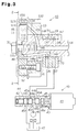
hydraulic chambers - As shown in Figure 3, two
oil passages camshaft 14 in the axial direction. Meanwhile, twooil passages cylinder head 79. Ring-like oil grooves cylinder head 79 and thebearing cap 67. Anoil hole 144, which is defined in thecamshaft 14, connects theoil passage 145 and theoil groove 36; while anotheroil hole 146, which is also defined in thecamshaft 14, connects theoil passage 147 and theoil groove 19. Anannular chamber 114 is defined around the left end portion of thecamshaft 14. Theboss 48 of therotor 11 has fourpassages 115 defined radially therein, and eachpassage 115 secures communication between theannular chamber 114 and the first hydraulic chambers 101 (Figure 2). Thecamshaft 14 has a ring-like oil groove 142 formed on itsouter surface 149. Anotheroil hole 148, which is also defined in thecamshaft 14, connects theoil passage 147 and theoil groove 142. The drivengear 13 contains fourpassages 134 defined radially therein, and thesepassages 134 connects theoil groove 142 and the second hydraulic chambers 102 (Figure 2). Oil is supplied to the firsthydraulic chambers 101 through theoil passage 36, theoil groove 18, theoil hole 144, theoil passage 145, theannular chamber 114 and thepassages 115. Meanwhile, oil is supplied to the secondhydraulic chambers 102 through theoil passage 37, theoil groove 19, theoil hole 146, theoil passage 147, theoil hole 148, theoil groove 142 and thepassages 134. - As described above, while the
camshaft 14 has some hollow spaces therein, only theoil passage 145 and thebolt hole 143 open to the left end face of thecamshaft 14, and theoil groove 142 opens to theouter surface 149 of thecamshaft 14. - A small clearance for permitting relative rotation between the
camshaft 14 and the drivengear 13 is defined between theouter surface 149 of thecamshaft 14 and theinner surface 133 of the drivengear 13. - Next, actions of an oil control valve (hereinafter referred to as an OCV) 40 for supplying oil pressure to the first and second
hydraulic chambers VVT 10 will be described. - As shown in Figure 3, the
OCV 40 has a plurality ofports first port 45a and thesecond port 45b to thehydraulic chambers OCV 40 is provided with asolenoid actuator 41, acasing 45, aspool 44 disposed in thecasing 45, aplunger 43 connected to thespool 44 and acoil spring 42 for urging thespool 44. Thespool 44 is reciprocated in the axial direction by performing duty control of theactuator 41. This reciprocating motion of thespool 44 achieves adjustment of the amount of oil to be supplied. - The
supply port 45t is connected via ahydraulic pump 46 to anoil pan 47; while the first and thesecond ports oil passages drain port 45r is connected to theoil pan 47. Thespool 44 is cylindrical valve body and haslands 44a, which interrupt the flow of the oil andpassages - The oil drawn or discharged by the
pump 46 under the operation of theOCV 40 is supplied through thesupply port 45t and thefirst port 45a to theoil passage 36 or through thesupply port 45t and thesecond port 45b to theoil passage 37. When the oil is introduced through thefirst port 45a, the oil is supplied to the firsthydraulic chambers 101 to increase the oil pressure in eachhydraulic chamber 101. Simultaneously, the oil in each secondhydraulic chamber 102 is discharged through theoil passage 37 to thesecond port 45b to reduce the oil pressure in the secondhydraulic chamber 102. Likewise, when the oil is introduced through thesecond port 45b, the oil pressure in each secondhydraulic chamber 102 is increased. Simultaneously, the oil in each firsthydraulic chamber 101 is discharged through theoil passage 36 to thefirst port 45a to reduce the oil pressure in the firsthydraulic chamber 101. Introduction of the oil through theports ports - As described above, when oil pressure is supplied to the first
hydraulic chamber 101, torque is applied to therotor 11 and thecamshaft 14 causing therotor 11 to move to the initial position as shown in Figure 2. That is, therotor 11 and thecamshaft 14 are rotated clockwise relative to the drivengear 13. Thus, the rotational phase of thecamshaft 14 with respect to the drivengear 13 and the crankshaft 73 (Figure 1) is changed, and the valve timing of the intake valves 77 (Figure 1), which are driven by thecamshaft 14, is advanced. The relative rotation of therotor 11 is restricted by theprotrusions 121. The valve timing of theintake valves 77 reaches the most advanced state. When the vanes reach the clockwise limit and at least onevane 112 about aprotrusion 121. - When oil pressure is supplied to the second
hydraulic chambers 102, torque is applied to therotor 11 and thecamshaft 14 to rotate them counterclockwise relative to the drivengear 13. Thus, the rotational phase of thecamshaft 14 with respect to the drivengear 13 and the crankshaft 73 (Figure 1) is changed, and the valve timing of the intake valves 77 (Figure 1), which are driven by thecamshaft 14, is delayed. When therotor 11 is rotated to the initial position shown in Figure 2, the valve timing of theintake valves 77 is the most delayed. - The oil supplied to the
oil groove 142 of thecamshaft 14 is fed to the small clearance between theouter surface 149 of thecamshaft 14 and theinner surface 133 of the drivengear 13 to facilitate smooth relative rotation of thecamshaft 14 relative to the drivengear 13. - The valve timing of the
intake valves 77 can be changed to the most delayed angle phase or to the most advanced angle phase by performing binary adjustment of the oil pressure values in thehydraulic chambers OCV 40. Otherwise, the valve timing of theintake valves 77 may be changed continuously between the most delayed angle phase and the most advanced angle phase by continuously adjusting the oil pressure values in thehydraulic chambers - As detailed above, according to the illustrated, only the
oil passage 145 and thebolt hole 143 open to the left end face of thecamshaft 14, and theoil groove 142 opens to thesurface 149 of thecamshaft 14. Unlike the prior art camshaft, in which all of the oil passages communicating with the first and second hydraulic chambers and the bolt hole open to the left end face of the camshaft, thecamshaft 14 of the first embodiment has less hollow space formed at the left end, so that the rigidity of thecamshaft 14 is improved. - The distance between the
passage 115 opening to each firsthydraulic chamber 101 and thepassage 134 opening to each secondhydraulic chamber 102 is increased compared with that of the prior art VVT. Accordingly, leakage of oil from thepassages 134 to the firsthydraulic chambers 101 or from thepassages 115 to the secondhydraulic chambers 102 is reduced, which reduces oil pressure interference between thehydraulic chambers hydraulic chambers VVT 10 is improved. - Next, the VVT according to a second embodiment of the present invention will be described referring to Figures 4 and 5. Parts of this embodiment are given the same or similar reference characters to corresponding parts of the first embodiment, and only differences from the first embodiment will be described. In this embodiment, the outside diameter at the lest end portion of the
camshaft 14 and the outside diameter of theboss 48 of therotor 11 are different from those in the first embodiment. - As shown in Figure 5, the outside diameter ⌀B at the distal end portion of a
camshaft 14 is designed to be smaller than the outside diameter ⌀A of the boss 38 of therotor 11. Thus, at the distal end face of thecamshaft 14, the boundary between theouter circumference 149 of thecamshaft 14 and theinner circumference 133 of the drivengear 13 is sealed by one side of the boss 38. Accordingly, that boundary is not exposed to the first and the secondhydraulic chambers 101, 102 (Figure 4). - In the second embodiment, again, a small clearance permitting relative rotation between the
camshaft 14 and the drivengear 13 is defined between theouter surface 149 of thecamshaft 14 and theinner surface 133 of the drivengear 13. Smooth rotation of thecamshaft 14 relative to the drivengear 13 is achieved by the oil supplied to the clearance. - In the second embodiment, since the clearance is sealed at the left end face of the
camshaft 14, leakage of the oil from the clearance is avoided. Accordingly, the desired oil pressure is supplied to thechambers VVT 16 is improved. - The VVT according to a third embodiment of the present invention will be described below referring to Figures 6 to 8.
- As shown in Figure 6, an
intake side camshaft 25, theexhaust camshaft 70 and thecrankshaft 73 are connected by achain 29 to which a predetermined tension is applied byidlers VVT 20 according to the third embodiment is attached to the left end of theintake side camshaft 25. When thecrankshaft 73 is rotated, thecamshafts crankshaft 73 via thechain 29 and thesprockets intake valves 77 and theexhaust valves 78 are driven under predetermined valve timings, respectively. - As shown in Figure 7, the
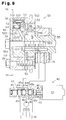
VVT 20 includes arotor 22, ahousing 24 surrounding therotor 22, asprocket 21 fixed to thehousing 24 via aplate 23, and acover 26 covering thehousing 24. - The
camshaft 25 supported on thecylinder head 79 has abolt hole 253 defined on the left end. Therotor 22 is fixed to that end of thecamshaft 25 by abolt 32 so that it is rotated integrally with thecamshaft 25. Thehousing 24 surrounding therotor 22 is rotatable relative to thecamshaft 25 and therotor 22. Thecover 26, theplate 23 and thesprocket 21 are fixed bybolts 33 to thehousing 24 so that they are rotated integrally. - As shown in Figure 8, the
rotor 22 has aboss 27 and fourvanes 222, each of which defines a firsthydraulic chamber 101 and a secondhydraulic chamber 102 in acorresponding recess 242 of thehousing 24. Anannular chamber 221 is defined between the left end portion of thecamshaft 25 and therotor 22. Theboss 27 of therotor 22 has fourpassages 225 defined radially therein, and thesepassages 225 connect between theannular chamber 221 and the firsthydraulic chambers 101. - As shown in Figure 7, the diameter ⌀A of the
boss 27 of therotor 22 is designed to be greater than the diameter ⌀B at the left end portion of thecamshaft 25. Thus, at the left end face of thecamshaft 25, the boundary between the outer circumference 231 of thecamshaft 25 and theinner circumference 211 of theplate 23 is sealed by theboss 27. - The
camshaft 25 contains anoil passage 255 defined axially therein, and theoil passage 255 opens at the left end to theannular chamber 221 and at the right to theoil hole 254. - One side of the
plate 23, which constitutes the wall surface of the first and secondhydraulic chambers oil holes 232, which communicate with to the secondhydraulic chambers 102, respectively. Anannular chamber 213 is defined between thesprocket 21 and theplate 23 to connect anoil groove 252 formed on the outer circumference of thecamshaft 25 with the oil holes 232. Thecamshaft 25 contains anoil passage 258 extending diagonally to connect theoil groove 252 and thebolt hole 253. Thecamshaft 25 has aradial oil passage 256 defined at thejournal 251 thereof so as to communicate with thebolt hole 253. - When oil is supplied from the
OCV 40 through theoil hole 254, theoil passage 255, theannular chamber 221, and thepassages 225 to the firsthydraulic chambers 101, therotor 22 and thecamshaft 25 are rotated clockwise relative to thehousing 24. Thus, the valve timing of the intake valves 77 (Figure 6) is advanced. When oil is supplied from theOCV 40 through theoil passage 256, thebolt hole 253, theoil passage 258, theoil groove 252, theannular chamber 213 and the oil holes 232 to the secondhydraulic chambers 102, therotor 22 and thecamshaft 25 are rotated counterclockwise relative to thehousing 24. Thus, the valve timing of theintake valves 77 is delayed. - In the third embodiment, again, the clearance between the outer surface 231 of the
camshaft 25 and the inner surface of theplate 23 is sealed by theboss 27 at the left end face of thecamshaft 25, so that leakage of the oil from the clearance is substantially avoided. Accordingly, the desired oil pressure is supplied to thechambers VVT 20 is improved. - In the third embodiment, the distance between the
passage 225 opening to the firsthydraulic chamber 101 and theoil hole 232 opening to the secondhydraulic chamber 102 is increased compared with that in the prior art VVT. Accordingly, oil leakage between thepassage 225 and theoil hole 232 is substantially reduced, which results in more accurate operation of theVVT 20. - In this embodiment, since the
plate 23 constitutes one side wall in each of thepressure chambers housing 24 can be increased by increasing the diameter of theplate 23 without increasing the diameter of thesprocket 21. As described above, by increasing the diameter of thehousing 24 and the radial length of eachvane 222, the force to be applied to eachvane 22 can be increased. Accordingly, the driving force of theVVT 20 is increased while vibration of therotor 22 attributed to fluctuation in the torque of thecamshaft 25 is reduced. Thus, the responsiveness of theVVT 20 is improved. - The VVT according to a fourth embodiment of the present invention will be described below referring to Figures 9 and 10. Differences from the third embodiment will primarily be described. The VVT of the fourth embodiment is applied to the same valve train as shown in Figure 6.
- As shown in Figure 9, the
VVT 50 according to the fourth embodiment is provided with alock pin 60 on one of fourvanes 522. Thelock pin 60 locks arotor 52 relative to asprocket 51 so as to retain therotor 52 at the initial position of Fig. 10. - Four
diagonal passages 525 are defined in therotor 52 to connect theannular chamber 221 to each of the firsthydraulic chambers 101. Onepassage 525 opens to the firsthydraulic chamber 101 and also to a releasing chamber 67 (to be described later). - As shown in Figure 9, the
lock pin 60 is housed in alock pin hole 523. Thelock pin 60 has a cylindrical shape and has alarge diameter portion 61 and a small diameter portion 62. Thelock pin 60 is urged by aspring 64, which urges thelock pin 60 toward aplate 53. Thelock pin 60 has a firstpressure receiving face 65, between thelarge diameter portion 61 and the small diameter portion 62, and a secondpressure receiving face 66, which is at the end of the small diameter portion 62. The firstpressure receiving surface 65 receives pressure from the oil supplied to the firsthydraulic chambers 101, whereas the secondpressure receiving surface 66 receives pressure from the oil supplied to the secondhydraulic chambers 102. - In the
lock pin hole 523, thelock pin 60 defines an annular releasingchamber 67, and the firstpressure receiving surface 65 is opposed to the releasingchamber 67. Oil pressure is supplied through thepassage 525 to the releasingchamber 67. - The
plate 53 contains a circularengaging hole 533 with which thelock pin 60 can engage. The secondpressure receiving surface 66 of thelock pin 60 is opposed to the engaginghole 533. - An
annular chamber 534 is defined between the right side of theplate 53 and the left end of acamshaft 55. Theannular chamber 534 communicates with each of secondhydraulic chambers 102 viaoil holes 532 and also with the engaginghole 533. Anoil passage 558, communicating with the annular chamber 543, is defined in thecamshaft 55, and thisoil passage 558 is connected to theOCV 40 via another oil passage (not shown) defined in thecamshaft 55. - When the engine 28 (Figure 6) is stopped, no oil pressure is supplied to the
hydraulic chambers oil pan 47. In this state, thelock pin 60 is urged toward theplate 53 by the force of thespring 64 and is maintained in engagement with the engaginghole 533. Accordingly, when the engine is stopped, rotation of therotor 52 relative to thesprocket 51 is restricted. - When the engine is started, the
rotor 52 is rotated integrally with thesprocket 51. Oil is gradually supplied to thehydraulic chambers hydraulic chambers rotor 52 is subject to fluctuation in the torque of thecamshaft 55. However, in the forth embodiment, since the movement of therotor 52 is restricted by thelock pin 60, backlash of therotor 52 is inhibited. - When the relative rotation of the
rotor 52 is restricted as described above, a great load is applied to the inner surface of theplate 53, which has the engaginghole 533 defined formed therein. In thisVVT 50, the inner surface of theplate 53 is surface hardened. As the material of theplate 53, boron steel subjected to induction hardening, Cr steel or Cr-Mn steel subjected to hardening and tempering treatment and carburizing treatment may be suitably employed. - Oil is supplied to the releasing
chamber 67 or theengagement hole 533, although the pressure thereof is low when the engine is initially started. Accordingly, thelock pin 60 receives the pressure from oil at the firstpressure receiving surface 65 or the secondpressure receiving surface 66, and when the oil pressure is high enough, thelock pin 60 is disengaged from the engaginghole 533 against the urging force of thespring 64. Thus, after the oil pressure reaches a certain level, the engagement of thelock pin 60 with the engaginghole 533 is released to permit therotor 52 to rotate relative to thesprocket 51. Once a sufficient oil pressure is reached, thelock pin 60 is maintained in the disengaged state until the engine is stopped. - The
rotor 52 and thecamshaft 55 are rotated relative to thesprocket 51 by supplying oil to either the firsthydraulic chambers 101 or the second hydraulic chambers 102 (with thepin 60 retracted), and thus the valve timing of the valves 77 (Figure 6) driven by thecamshaft 55 can be changed. - When the engine is stopped, the supply of oil from the
hydraulic pump 46 is stopped. When the engine is stopped, thespool 44 of theOVC 40 is stopped at the position where oil is supplied to the secondhydraulic chambers 102, and the oil in each firsthydraulic chamber 101 is discharged into theoil pan 47. Thus, therotor 52 rotates to the initial position shown in Figure 10. In this process, the oil pressure in the releasingchamber 67 and theengaging hole 533 is lowered, so that thelock pin 60 is engaged again with the engaginghole 533 to restrict relative rotation of therotor 52. - As described above, since the
VVT 50 is provided with a surface-hardenedplate 53, damage to theplate 53 is prevented even if thelock pin 60 are frequently brought into contact with the inner surface of theplate 53. - In the fourth embodiment, once by the
lock pin 60 is released, oil pressure is constantly supplied to either the releasingchamber 67 or theengaging hole 533, and thelock pin 60 is entirely retracted into thelock pin hole 532. Therefor, thelock pin 60 does not contact theplate 53 when the oil pressure is at normal operating levels. - According to the fourth embodiment, the
sprocket 51, thehousing 54 and theplate 53 are fixed by abolt 34. However, it is possible to form theplate 53 using a sintered material and to join thesprocket 51, theplate 53 and thehousing 54 with a brazing filler alloy when theplate 53 is sintered, thus improving seal between thehousing 54 and theplate 53. - Although only several embodiments of the present invention have been described herein, it should be apparent to those skilled in the art that the present invention may be embodied in many other specific forms without departing from the spirit or scope of the invention. Particularly, it should be understood that the invention may be embodied in the following forms.
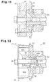
- As shown in Figure 11, the
plates sprocket 21 is increased, anannular chamber 69 can be formed as shown. - In the foregoing embodiments, while the valve timing of the
intake valves 77 is changed, it is also possible to change the valve timing of the exhaust valves by attaching the VVT to the exhaust side camshaft. - In the foregoing embodiments, while the rotational phase of the intake side camshaft provided with the VVT is changed with respect to the crankshaft, it is also possible to change the rotational phase of the camshaft that is nor attached to the VVT. For example, in Figure 1, the
pulley 71 can be connected to the right end of theintake camshaft 14, and thepulley 71 can be connected to the pulley 76 of thecrankshaft 73 by thebelt 72. With this construction, theintake camshaft 14 is rotated synchronously with thecrankshaft 73. Under operation of theVVT 10, the rotational phase of the exhaust side camshaft can be changed 70 relative to thecrankshaft 73. - Therefore, the present examples and embodiments are to be considered as illustrative and not restrictive and the invention is not to be limited to the details given herein, but may be modified within the scope and equivalence of the appended claims.
A variable valve timing mechanism is provided at the distal end of a camshaft (14; 25; 39; 55) for changing a valve timing of an engine valve (77). A rotor (11; 22; 52) is fixed to the distal end face of the camshaft (14; 25; 39; 55), and the rotor has four vanes (112; 222; 522) protruding radially outward. A housing (12; 24; 54) is disposed to surround the rotor (11; 22; 52) to be rotatable relative to the rotor (11; 22; 52) and the camshaft (14; 25; 39; 55), and the housing (12; 24; 54) has recesses (122; 242; 542) on the inner circumference. Each recess (122; 242; 542) is divided by the vane (112; 222; 522) into a first pressure chamber (101) and a second pressure chamber (102). A first passage (145; 255; 555) is defined in the camshaft (14; 25; 39; 55), for supplying a hydraulic fluid pressure to the first pressure chamber (101) so as to change the rotational phase of the second rotor (12, 13; 21, 23, 24; 51, 53, 54) with respect to the camshaft (14; 25; 39; 55), and the first passage (145; 255; 555) has an opening at the distal end face of the camshaft (14; 25; 39; 55). A second passage (148; 258; 558) is defined in the camshaft (14; 25; 39; 55), for supplying a fluid pressure to the second pressure chamber (102) so as to change the rotational phase of the second rotor (12, 13; 21, 23, 24; 51, 53, 54) with respect to the camshaft (14; 25; 39; 55), and the second passage (148; 258; 558) has an opening at outer circumference (149; 231) of the camshaft (14; 25; 39; 55).
Claims (17)
- An apparatus for adjusting valve timing of a valve (77) of an engine, the valve (77) being actuated by a cam, the apparatus comprising, a camshaft (14; 25; 39; 55) for driving the cam, the camshaft (14; 25; 39; 55) having a circumferential surface and a first end, wherein the first end has an end face, a first rotor (11; 22; 52) fixed to the end face of the camshaft (14; 25; 39; 55), the first rotor (11; 22; 52) having radially extending vanes (112; 222; 522), a second rotor (12, 13; 21, 23, 24; 51, 53, 54) arranged to surround the first rotor (11; 22; 52) and to be rotatable relative to the first rotor (11; 22; 52), the second rotor (12, 13; 21, 23, 24; 51, 53, 54) having a recess (122; 242; 542) formed therein, the recess (122; 242; 542) being divided by the vane (112; 222; 522) into a first pressure chamber (101) and a second pressure chamber (102), a first passage (145; 255; 555) defined in the camshaft (14; 25; 39; 55), for supplying hydraulic fluid to the first pressure chamber (101) to change the rotational phase of the second rotor (12, 13; 21, 23, 24; 51, 53, 54) with respect to the camshaft (14; 25; 39; 55), the first passage (145; 255; 555) having an upstream end and a downstream end with respect to the direction of fluid flow during filling of the first hydraulic chamber (101), and a second passage (148; 258; 558) defined in the camshaft (14; 25; 39; 55) for supplying hydraulic fluid to the second pressure chamber (102) to change the rotational phase of the second rotor (12, 13; 21, 23, 24; 51, 53, 54) with respect to the camshaft (14; 25; 39; 55), the second passage (148; 258; 558) having an upstream end and a downstream end with respect to the direction of fluid flow during filling of the second hydraulic chamber (102), the apparatus characterized by the first passage (145; 255; 555) having a downstream opening in the end face, and the second passage (148; 258; 558) having a downstream opening in a surface of the cam other than the end face.
- The apparatus according to Claim 1, wherein a downstream end of the first passage (145; 255; 555) extends primarily in the axial direction of the camshaft (14; 25; 39; 55), and a downstream end of the second passage (148; 258; 558) extends primarily in the radial direction of the camshaft (14; 25; 39; 55).
- The apparatus according to Claim 2, the camshaft (14; 25; 39; 55) has an outer bearing surface (149; 231), while the second rotor (12, 13; 21, 23, 24; 51, 53, 54) has an inner bearing surface that contacts the outer bearing surface (149; 231) of the camshaft (14; 25; 39; 55), and the downstream opening of the second passage (148; 258; 558) is in the outer bearing surface (149; 231) of the camshaft (14; 25; 39; 55).
- The apparatus according to Claim 3, wherein the first rotor (11; 22; 52) has a cylindrical boss (27; 48), the outside diameter of which is smaller than the outside diameter of the end face.
- The apparatus according to Claim 4, wherein the first rotor (11; 22; 52) has a third passage (115; 225; 525) for connecting the first passage (145; 255; 555) and the first pressure chamber (101), and the second rotor (12, 13; 21, 23, 24; 51, 53, 54) has a fourth passage (134; 213, 232; 532, 534) for connecting the second passage (148; 258; 558) and the second pressure chamber (102).
- The apparatus according to any one of Claims 1 to 5, wherein the first end of the camshaft (14; 25; 39; 55) has a flange face that is axially spaced from the end face, and the downstream opening of the second passage (148; 258; 558) is formed in the flange face.
- The apparatus according to any one of Claims 1 to 5, wherein the second rotor (12, 13; 21, 23, 24; 51, 53, 54) is surrounded by a housing (12; 24; 54).
- The apparatus according to Claim 7, wherein one of the vanes (522) has locking means (60) for restricting relative rotation between the first and second rotors (51-54).
- The apparatus according to Claim 8, wherein the locking means includes a lock pin (60) and a recess (542) with which the lock pin (60) is selectively engaged.
- The apparatus according to Claim 5, wherein the opening of the third passage (115; 225; 525) in the first pressure chamber (101) is spaced far from the axis of the camshaft (14; 25; 39; 55) compared with the opening of the fourth passage (134; 213, 232; 532, 534) of the second pressure chamber (102).
- An apparatus for adjusting the valve timing of an engine valve (77) with respect to a crankshaft (73), the valve (77) being actuated by a cam, the apparatus comprising, a rotatable shaft (14; 25; 39; 55), the rotatable shaft (14; 25; 39; 55) having a circumferential surface and a first end, wherein the first end has an end face, a first rotor (11; 22; 52) rotatably mounted to the first end such that the first rotor (11; 22; 52) is coaxial to the rotatable shaft (14; 25; 39; 55), a second rotor (12, 13; 21, 23, 24; 51, 53, 54) mounted coaxially to the first end of the rotatable shaft (14; 25; 39; 55) such that the second rotor (12, 13; 21, 23, 24; 51, 53, 54) is rotatable relative to the first rotor (11; 22; 52), wherein one of the first and second rotors (11-13; 21-24; 51-54) is fixed in locked synchronism with the crankshaft (73) and the other is fixed to rotate in locked synchronism with the cam such that relative rotation between the two rotors changes the timing of the valve (77) with respect to the crankshaft (73), hydraulic actuation means for causing relative movement between the rotors, wherein a vane (112; 222; 522) is formed on one of the rotors, and a recess (122; 242; 542) is formed in the other of the rotors, such that the vane (112; 222; 522) divides the recess (122; 242; 542) into first and second hydraulic chambers (101, 102), a first passage (145; 255; 555) formed in the rotatable shaft (14; 25; 39; 55) for supplying hydraulic fluid to the first hydraulic chamber (101) for rotating the first rotor (11; 22; 52) in a first direction with respect to the second rotor (12, 13; 21, 23, 24; 51, 53, 54), the first passage (145; 255; 555) having an upstream end and a downstream end with respect to the direction of fluid flow during filling of the first hydraulic chamber (101), a second passage (148; 258; 558) formed in the rotatable shaft (14; 25; 39; 55) for supplying hydraulic fluid to the second hydraulic chamber (102) for rotating the first rotor (11; 22; 52) in a second direction with respect to the second rotor (12, 13; 21, 23, 24; 51, 53, 54), the second passage (148; 258; 558) having an upstream end and a downstream end with respect to the direction of fluid flow during filling of the second hydraulic chamber (102), the apparatus characterized by that the first passage (145; 255; 555) has a downstream opening in the end face, and the second passage (148; 258; 558) has downstream opening in a surface of the rotatable shaft (14; 25; 39; 55) other than the end face, and the downstream opening of the second passage (148; 258; 558) is radially further from the axis of the rotatable shaft (14; 25; 39; 55) than the downstream opening of the first passage (145; 255; 555).
- The apparatus according to Claim 11, wherein locking means (60) are provided for locking the first rotor (11; 22; 52) to the second rotor (12, 13; 21, 23, 24; 51, 53, 54) when the engine is not running, wherein the locking means includes a locking member (60) connected to one of the rotors, wherein the locking member (60) is spring biased into a locking position when the engine is not running, and a locking member receiver (533) on the other of the rotors, wherein the locking member (60) engages the locking member receiver (533) to lock the rotor together, and wherein the hydraulic fluid urges the locking member (60) to an unlocked position when the engine reaches a predetermined running condition.
- The apparatus according to Claim 12, wherein a downstream portion of the first passage (145; 255; 555) extends generally in an axial direction of the rotatable shaft (14; 25; 39; 55), and wherein a downstream portion of the second passage (148; 258; 558) extends generally in a radial direction of the rotatable shaft (14; 25; 39; 55).
- The apparatus according to Claim 13, wherein the first end of the shaft (55) has a flange face (534) that is axially spaced from the end face, and the downstream opening of the second passage (558) is formed in the flange face (534).
- The apparatus according to any one of Claims 1 to 5 and 11 to 14, wherein the engine has a crankshaft (73), the apparatus further comprising a transmitting means (27) for transmitting engine power from the crankshaft (73) to the second rotor (12, 13; 21, 23, 24; 51, 53, 54), and wherein the second rotor (12, 13; 21, 23, 24; 51, 53, 54) is rotated in fixed synchronism with the crankshaft (73).
- The apparatus according to Claim 15, wherein the transmitting means includes a second camshaft (70), and one end of the second camshaft (70) is connected to the crankshaft (73), while the other end of the second camshaft (70) is connected to the second rotor (12, 13; 21, 23, 24; 51, 53, 54).
- The apparatus according to any one of Claims 1 to 5 and 11 to 14, further comprising a hydraulic control unit (40) for controlling the flow of fluid supplied to the first and second pressure chambers (101, 102), a first conduit for connecting the first passage (145; 255; 555) to the control unit (40) and a second conduit for connecting the second passage (148; 258; 558) to the control unit (40).
Applications Claiming Priority (6)
| Application Number | Priority Date | Filing Date | Title |
|---|---|---|---|
| JP8648196 | 1996-04-09 | ||
| JP86481/96 | 1996-04-09 | ||
| JP8648196 | 1996-04-09 | ||
| JP09064123A JP3077621B2 (en) | 1996-04-09 | 1997-03-18 | Variable valve timing mechanism for internal combustion engine |
| JP64123/97 | 1997-03-18 | ||
| JP6412397 | 1997-03-18 |
Publications (2)
| Publication Number | Publication Date |
|---|---|
| EP0801212A1 true EP0801212A1 (en) | 1997-10-15 |
| EP0801212B1 EP0801212B1 (en) | 2000-07-26 |
Family
ID=26405258
Family Applications (1)
| Application Number | Title | Priority Date | Filing Date |
|---|---|---|---|
| EP97105771A Expired - Lifetime EP0801212B1 (en) | 1996-04-09 | 1997-04-08 | Engine variable valve timing mechanism |
Country Status (7)
| Country | Link |
|---|---|
| US (1) | US5724929A (en) |
| EP (1) | EP0801212B1 (en) |
| JP (1) | JP3077621B2 (en) |
| KR (1) | KR100265982B1 (en) |
| CN (1) | CN1090277C (en) |
| DE (1) | DE69702633T2 (en) |
| ID (1) | ID18168A (en) |
Cited By (11)
| Publication number | Priority date | Publication date | Assignee | Title |
|---|---|---|---|---|
| DE19903594A1 (en) * | 1998-02-03 | 1999-08-12 | Toyota Motor Co Ltd | Adjustable valve control device for controlling valve timing in internal combustion (IC) engine |
| WO2000061920A1 (en) | 1999-04-14 | 2000-10-19 | Daimlerchrysler Ag | Device for adjusting the relative angle of a cam shaft |
| US6173687B1 (en) | 1997-11-14 | 2001-01-16 | Mitsubishi Denki Kabushiki Kaisha | Hydraulic apparatus for adjusting the timing of opening and closing of an engine valve |
| WO2001011202A1 (en) * | 1999-08-04 | 2001-02-15 | INA Wälzlager Schaeffler oHG | Device for varying the valve control times of an internal combustion engine, especially a camshaft adjusting device with a pivotal impeller wheel |
| DE19938596A1 (en) * | 1999-08-14 | 2001-02-15 | Schaeffler Waelzlager Ohg | Vane cell adjuster for rotary angle between camshaft and crankshaft in IC engines has locking pin released by oil pressure in late adjusting chamber, and held unlocked by pressure in early and late adjusting chambers |
| DE19951391A1 (en) * | 1999-10-26 | 2001-07-05 | Schaeffler Waelzlager Ohg | Device for changing the control times of gas exchange valves of an internal combustion engine, in particular hydraulic camshaft adjusting device in the direction of rotation |
| EP1286023A2 (en) * | 2001-08-14 | 2003-02-26 | BorgWarner Inc. | Cam phaser for a four cylinder engine |
| DE10045418B4 (en) * | 1999-09-17 | 2006-01-12 | Hitachi, Ltd. | Device for controlling the valve setting for internal combustion engines |
| WO2006125536A1 (en) * | 2005-05-23 | 2006-11-30 | Schaeffler Kg | Device for the variable adjustment of the control times for gas exchange valves in an internal combustion engine |
| WO2010003745A1 (en) * | 2008-07-07 | 2010-01-14 | Schaeffler Kg | Camshaft adjuster |
| WO2011061100A1 (en) * | 2009-11-17 | 2011-05-26 | Schaeffler Technologies Gmbh & Co. Kg | Rotor, in particular for a camshaft adjuster, method for producing a rotor and device for adjusting the angle of rotation of a camshaft relative to a crankshaft of an engine |
Families Citing this family (40)
| Publication number | Priority date | Publication date | Assignee | Title |
|---|---|---|---|---|
| JP3116858B2 (en) * | 1996-11-29 | 2000-12-11 | トヨタ自動車株式会社 | Variable valve timing mechanism for internal combustion engine |
| DE69731012T2 (en) * | 1996-12-12 | 2005-11-17 | Aisin Seiki K.K., Kariya | Valve control device |
| JP3812689B2 (en) * | 1996-12-12 | 2006-08-23 | アイシン精機株式会社 | Valve timing control device |
| JP3029020B2 (en) * | 1997-04-25 | 2000-04-04 | 株式会社デンソー | Valve timing adjustment device for internal combustion engine |
| JP3760568B2 (en) * | 1997-06-05 | 2006-03-29 | アイシン精機株式会社 | Valve timing control device |
| JP3760566B2 (en) * | 1997-06-05 | 2006-03-29 | アイシン精機株式会社 | Valve timing control device |
| JP3823451B2 (en) * | 1997-06-24 | 2006-09-20 | アイシン精機株式会社 | Valve timing control device |
| JP3191730B2 (en) * | 1997-07-17 | 2001-07-23 | 三菱電機株式会社 | Hydraulic valve timing adjustment device |
| US6170447B1 (en) * | 1997-11-06 | 2001-01-09 | Ina Schaeffler Ohg | Inner seal for a camshaft adjusting device in an internal combustion engine, specially a blade cell adjusting device |
| DE19808618A1 (en) * | 1998-02-28 | 1999-09-02 | Schaeffler Waelzlager Ohg | Locking device for a device for changing the control times of gas exchange valves of an internal combustion engine, in particular for a vane cell adjustment device |
| JP3960917B2 (en) * | 2001-01-29 | 2007-08-15 | 株式会社日立製作所 | Valve timing control device for internal combustion engine |
| DE10213081A1 (en) * | 2002-03-20 | 2003-10-02 | Hydraulik Ring Gmbh | Valve control for adjusting the stroke of valves in motor vehicles |
| JP2004263643A (en) * | 2003-03-03 | 2004-09-24 | Mitsubishi Electric Corp | Valve timing adjusting device |
| JP4177197B2 (en) * | 2003-08-08 | 2008-11-05 | 株式会社日立製作所 | Valve timing control device for internal combustion engine |
| JP2005061261A (en) * | 2003-08-08 | 2005-03-10 | Hitachi Unisia Automotive Ltd | Variable valve system for internal combustion engine |
| JP4055691B2 (en) * | 2003-10-03 | 2008-03-05 | 松下電器産業株式会社 | Industrial robot |
| DE10356908B4 (en) * | 2003-12-02 | 2007-11-22 | Hydraulik-Ring Gmbh | Camshaft adjusting device for internal combustion engines of vehicles, preferably motor vehicles |
| DE102005026553B3 (en) * | 2005-06-08 | 2006-09-07 | Hydraulik-Ring Gmbh | Reduced-leakage adjuster for camshaft has a rotor consisting of at least cover and core, forming covered channel sector parallel to one side when in contact |
| DE102006049243A1 (en) | 2006-10-18 | 2008-04-24 | Mahle International Gmbh | Actuator for two parallel rotating camshafts |
| JP4697547B2 (en) * | 2006-11-13 | 2011-06-08 | 株式会社デンソー | Valve timing adjustment device |
| DE102007054547A1 (en) * | 2007-11-15 | 2009-05-20 | Schaeffler Kg | Engine control strategy for hydraulic camshaft adjuster with mechanical center lock |
| JP5093587B2 (en) * | 2007-12-07 | 2012-12-12 | アイシン精機株式会社 | Valve timing control device |
| JP2010236448A (en) * | 2009-03-31 | 2010-10-21 | Yamaha Motor Co Ltd | Water jet propulsion watercraft |
| JP2010242612A (en) * | 2009-04-06 | 2010-10-28 | Yamaha Motor Co Ltd | Water jet propulsion watercraft |
| JP4900451B2 (en) * | 2009-11-09 | 2012-03-21 | 株式会社デンソー | Valve timing adjustment device |
| DE112010005079T5 (en) | 2010-01-04 | 2012-11-22 | Borgwarner Inc. | Stage with oil pressure support |
| US8607748B2 (en) * | 2010-01-14 | 2013-12-17 | Mitsubishi Jidosha Kogyo Kabushiki Kaisha | Engine equipped with variable valvetrain |
| JP5182326B2 (en) * | 2010-06-09 | 2013-04-17 | トヨタ自動車株式会社 | Flow control valve |
| JP5569458B2 (en) * | 2011-04-18 | 2014-08-13 | 株式会社デンソー | Valve timing adjustment device |
| JP6118802B2 (en) * | 2011-08-30 | 2017-04-19 | ボーグワーナー インコーポレーテッド | Oil channel structure for phaser or double phaser |
| DE102012025791B3 (en) * | 2012-02-02 | 2021-03-25 | Schaeffler Technologies AG & Co. KG | Arrangement of a volume memory in the camshaft adjuster |
| DE102012201563A1 (en) * | 2012-02-02 | 2013-08-08 | Schaeffler Technologies AG & Co. KG | Check valve for camshaft adjuster with oil reservoir |
| CN103375212B (en) * | 2012-04-26 | 2016-12-28 | 日立汽车系统株式会社 | The variable valve gear of internal combustion engine |
| CN102935584B (en) * | 2012-11-21 | 2014-11-05 | 武汉船用机械有限责任公司 | Method for machining oil distributor shell |
| CN104179542B (en) * | 2013-05-24 | 2018-08-21 | 舍弗勒技术股份两合公司 | Camshaft phase adjuster and its rotor and variable cam timing system |
| DE102013221886A1 (en) | 2013-10-28 | 2015-04-30 | Borgwarner Inc. | Internal combustion engine with a phaser and associated control method |
| DE102014208598B4 (en) * | 2014-05-08 | 2020-10-29 | Schaeffler Technologies AG & Co. KG | Camshaft adjuster with a hydraulic chamber sealing element that can be switched back and forth to achieve a hydraulic freewheel |
| CN104455944A (en) * | 2014-11-29 | 2015-03-25 | 南京萨伯工业设计研究院有限公司 | Motor housing and machining method thereof |
| CN105736083A (en) * | 2014-12-12 | 2016-07-06 | 舍弗勒技术股份两合公司 | Camshaft phase regulator |
| CN112796849A (en) * | 2019-11-14 | 2021-05-14 | 舍弗勒技术股份两合公司 | Rotor for camshaft phaser and camshaft phaser |
Citations (3)
| Publication number | Priority date | Publication date | Assignee | Title |
|---|---|---|---|---|
| FR1085087A (en) * | 1953-06-17 | 1955-01-27 | Device for controlling the relative angular displacement of two co-axial parts of a transmission | |
| US4858572A (en) * | 1987-09-30 | 1989-08-22 | Aisin Seiki Kabushiki Kaisha | Device for adjusting an angular phase difference between two elements |
| JPH05113112A (en) * | 1991-10-24 | 1993-05-07 | Toyo A Tec Kk | Valve opening/closing timing changing device for engine |
Family Cites Families (3)
| Publication number | Priority date | Publication date | Assignee | Title |
|---|---|---|---|---|
| JPS5429011B2 (en) * | 1974-07-21 | 1979-09-20 | ||
| US5107804A (en) * | 1989-10-16 | 1992-04-28 | Borg-Warner Automotive Transmission & Engine Components Corporation | Variable camshaft timing for internal combustion engine |
| JPH0511312A (en) * | 1991-07-04 | 1993-01-22 | Nikon Corp | Exposure controller for camera |
-
1997
- 1997-03-18 JP JP09064123A patent/JP3077621B2/en not_active Expired - Fee Related
- 1997-04-07 ID IDP971164A patent/ID18168A/en unknown
- 1997-04-07 US US08/835,252 patent/US5724929A/en not_active Expired - Lifetime
- 1997-04-08 DE DE69702633T patent/DE69702633T2/en not_active Expired - Lifetime
- 1997-04-08 KR KR1019970012776A patent/KR100265982B1/en not_active IP Right Cessation
- 1997-04-08 EP EP97105771A patent/EP0801212B1/en not_active Expired - Lifetime
- 1997-04-09 CN CN97111244A patent/CN1090277C/en not_active Expired - Lifetime
Patent Citations (3)
| Publication number | Priority date | Publication date | Assignee | Title |
|---|---|---|---|---|
| FR1085087A (en) * | 1953-06-17 | 1955-01-27 | Device for controlling the relative angular displacement of two co-axial parts of a transmission | |
| US4858572A (en) * | 1987-09-30 | 1989-08-22 | Aisin Seiki Kabushiki Kaisha | Device for adjusting an angular phase difference between two elements |
| JPH05113112A (en) * | 1991-10-24 | 1993-05-07 | Toyo A Tec Kk | Valve opening/closing timing changing device for engine |
Non-Patent Citations (1)
| Title |
|---|
| PATENT ABSTRACTS OF JAPAN vol. 017, no. 479 (M - 1471) 31 August 1993 (1993-08-31) * |
Cited By (22)
| Publication number | Priority date | Publication date | Assignee | Title |
|---|---|---|---|---|
| US6173687B1 (en) | 1997-11-14 | 2001-01-16 | Mitsubishi Denki Kabushiki Kaisha | Hydraulic apparatus for adjusting the timing of opening and closing of an engine valve |
| DE19903594C2 (en) * | 1998-02-03 | 2003-06-18 | Toyota Motor Co Ltd | Adjustable valve control device |
| US6170448B1 (en) | 1998-02-03 | 2001-01-09 | Toyota Jidosha Kabushiki Kaisha | Variable valve timing apparatus |
| DE19903594A1 (en) * | 1998-02-03 | 1999-08-12 | Toyota Motor Co Ltd | Adjustable valve control device for controlling valve timing in internal combustion (IC) engine |
| WO2000061920A1 (en) | 1999-04-14 | 2000-10-19 | Daimlerchrysler Ag | Device for adjusting the relative angle of a cam shaft |
| DE19916675A1 (en) * | 1999-04-14 | 2000-11-30 | Daimler Chrysler Ag | Device for the relative angular adjustment of a camshaft |
| DE19916675B4 (en) * | 1999-04-14 | 2005-07-07 | Daimlerchrysler Ag | Device for relative angular adjustment of a camshaft |
| WO2001011202A1 (en) * | 1999-08-04 | 2001-02-15 | INA Wälzlager Schaeffler oHG | Device for varying the valve control times of an internal combustion engine, especially a camshaft adjusting device with a pivotal impeller wheel |
| US6601554B1 (en) | 1999-08-04 | 2003-08-05 | Ina Walzlager Schaeffler Ohg | Device for varying the valve control times of an internal combustion engine, especially a camshaft adjusting device with a pivotal impeller wheel |
| DE19938596A1 (en) * | 1999-08-14 | 2001-02-15 | Schaeffler Waelzlager Ohg | Vane cell adjuster for rotary angle between camshaft and crankshaft in IC engines has locking pin released by oil pressure in late adjusting chamber, and held unlocked by pressure in early and late adjusting chambers |
| DE10045418B4 (en) * | 1999-09-17 | 2006-01-12 | Hitachi, Ltd. | Device for controlling the valve setting for internal combustion engines |
| DE19951391A1 (en) * | 1999-10-26 | 2001-07-05 | Schaeffler Waelzlager Ohg | Device for changing the control times of gas exchange valves of an internal combustion engine, in particular hydraulic camshaft adjusting device in the direction of rotation |
| US6418893B1 (en) | 1999-10-26 | 2002-07-16 | Ina Walzlager Schaeffler Ohg | Device for varying valve timing of gas exchange valves of an internal combustion engine, in particular a hydraulic camshaft adjusting device of a rotary piston type |
| EP1286023A2 (en) * | 2001-08-14 | 2003-02-26 | BorgWarner Inc. | Cam phaser for a four cylinder engine |
| EP1286023A3 (en) * | 2001-08-14 | 2003-08-20 | BorgWarner Inc. | Cam phaser for a four cylinder engine |
| US6763791B2 (en) | 2001-08-14 | 2004-07-20 | Borgwarner Inc. | Cam phaser for engines having two check valves in rotor between chambers and spool valve |
| WO2006125536A1 (en) * | 2005-05-23 | 2006-11-30 | Schaeffler Kg | Device for the variable adjustment of the control times for gas exchange valves in an internal combustion engine |
| US7707981B2 (en) | 2005-05-23 | 2010-05-04 | Schaeffler Kg | Device for the variable adjustment of the control times for gas exchange valves in an internal combustion engine |
| WO2010003745A1 (en) * | 2008-07-07 | 2010-01-14 | Schaeffler Kg | Camshaft adjuster |
| US8434438B2 (en) | 2008-07-07 | 2013-05-07 | Schaeffler Technologies AG & Co. KG | Camshaft adjuster |
| WO2011061100A1 (en) * | 2009-11-17 | 2011-05-26 | Schaeffler Technologies Gmbh & Co. Kg | Rotor, in particular for a camshaft adjuster, method for producing a rotor and device for adjusting the angle of rotation of a camshaft relative to a crankshaft of an engine |
| US8490589B2 (en) | 2009-11-17 | 2013-07-23 | Schaeffler Technologies AG & Co. KG | Rotor, in particular for a camshaft adjuster, method for producing a rotor and device for adjusting the angle of rotation of a camshaft relative to a crankshaft of an engine |
Also Published As
| Publication number | Publication date |
|---|---|
| CN1175658A (en) | 1998-03-11 |
| ID18168A (en) | 1998-03-12 |
| DE69702633T2 (en) | 2001-04-05 |
| JP3077621B2 (en) | 2000-08-14 |
| EP0801212B1 (en) | 2000-07-26 |
| KR19980076196A (en) | 1998-11-16 |
| US5724929A (en) | 1998-03-10 |
| JPH09329005A (en) | 1997-12-22 |
| CN1090277C (en) | 2002-09-04 |
| KR100265982B1 (en) | 2000-10-02 |
| DE69702633D1 (en) | 2000-08-31 |
Similar Documents
| Publication | Publication Date | Title |
|---|---|---|
| US5724929A (en) | Engine variable valve timing mechanism | |
| EP0799977B1 (en) | Variable valve timing mechanism for internal combustion engine | |
| US6006708A (en) | Valve timing controlling apparatus for internal combustion engine | |
| EP2006500B1 (en) | Cam phaser with vanes on rotor and a locking pin | |
| EP1400661B1 (en) | Spool valve controlled VCT locking pin release mechanism | |
| EP0915234B1 (en) | Valve timing changing apparatus for internal combustion engine | |
| JP3116858B2 (en) | Variable valve timing mechanism for internal combustion engine | |
| JP2003106115A (en) | Phase shifter | |
| JPH11236807A (en) | Variable valve timing device | |
| JP2947165B2 (en) | Valve timing changing device for internal combustion engine | |
| US5803029A (en) | Valve performance controller for internal combustion engine | |
| EP0821139B1 (en) | Oil supply structure in variable valve timing mechanism | |
| US20030079703A1 (en) | Variable valve control apparatus for internal combustion engine and method thereof | |
| EP0801211B1 (en) | Variable valve timing mechanism of engine | |
| JPH10141022A (en) | Valve timing control device for internal combustion engine | |
| EP0816643A1 (en) | Hydraulic actuator in an internal combustion engine | |
| JPH09250310A (en) | Valve timing changing device for internal combustion engine | |
| JP3627340B2 (en) | Valve timing control device | |
| JP3085219B2 (en) | Valve timing control device for internal combustion engine | |
| JPH10159519A (en) | Valve timing controlling device for internal combustion engine | |
| JPH11280414A (en) | Dohc engine with variable valve timing device | |
| JP3551343B2 (en) | Valve timing control device | |
| JP2950263B2 (en) | Valve timing control device for internal combustion engine | |
| JP3221336B2 (en) | Valve timing control device for internal combustion engine | |
| JPH10231712A (en) | Valve timing control device for internal combustion engine |
Legal Events
| Date | Code | Title | Description |
|---|---|---|---|
| PUAI | Public reference made under article 153(3) epc to a published international application that has entered the european phase |
Free format text: ORIGINAL CODE: 0009012 |
|
| 17P | Request for examination filed |
Effective date: 19970408 |
|
| AK | Designated contracting states |
Kind code of ref document: A1 Designated state(s): DE FR GB |
|
| 17Q | First examination report despatched |
Effective date: 19980331 |
|
| GRAG | Despatch of communication of intention to grant |
Free format text: ORIGINAL CODE: EPIDOS AGRA |
|
| GRAG | Despatch of communication of intention to grant |
Free format text: ORIGINAL CODE: EPIDOS AGRA |
|
| GRAH | Despatch of communication of intention to grant a patent |
Free format text: ORIGINAL CODE: EPIDOS IGRA |
|
| GRAH | Despatch of communication of intention to grant a patent |
Free format text: ORIGINAL CODE: EPIDOS IGRA |
|
| GRAA | (expected) grant |
Free format text: ORIGINAL CODE: 0009210 |
|
| AK | Designated contracting states |
Kind code of ref document: B1 Designated state(s): DE FR GB |
|
| ET | Fr: translation filed | ||
| REF | Corresponds to: |
Ref document number: 69702633 Country of ref document: DE Date of ref document: 20000831 |
|
| PLBE | No opposition filed within time limit |
Free format text: ORIGINAL CODE: 0009261 |
|
| STAA | Information on the status of an ep patent application or granted ep patent |
Free format text: STATUS: NO OPPOSITION FILED WITHIN TIME LIMIT |
|
| 26N | No opposition filed | ||
| REG | Reference to a national code |
Ref country code: GB Ref legal event code: IF02 |
|
| REG | Reference to a national code |
Ref country code: GB Ref legal event code: 746 Effective date: 20130128 |
|
| REG | Reference to a national code |
Ref country code: DE Ref legal event code: R084 Ref document number: 69702633 Country of ref document: DE Effective date: 20130125 |
|
| REG | Reference to a national code |
Ref country code: FR Ref legal event code: PLFP Year of fee payment: 20 |
|
| PGFP | Annual fee paid to national office [announced via postgrant information from national office to epo] |
Ref country code: FR Payment date: 20160309 Year of fee payment: 20 |
|
| PGFP | Annual fee paid to national office [announced via postgrant information from national office to epo] |
Ref country code: DE Payment date: 20160405 Year of fee payment: 20 Ref country code: GB Payment date: 20160406 Year of fee payment: 20 |
|
| REG | Reference to a national code |
Ref country code: DE Ref legal event code: R071 Ref document number: 69702633 Country of ref document: DE |
|
| REG | Reference to a national code |
Ref country code: GB Ref legal event code: PE20 Expiry date: 20170407 |
|
| PG25 | Lapsed in a contracting state [announced via postgrant information from national office to epo] |
Ref country code: GB Free format text: LAPSE BECAUSE OF EXPIRATION OF PROTECTION Effective date: 20170407 |