EP0801208A2 - Cooled rotor assembly for a turbine engine - Google Patents
Cooled rotor assembly for a turbine engine Download PDFInfo
- Publication number
- EP0801208A2 EP0801208A2 EP97302503A EP97302503A EP0801208A2 EP 0801208 A2 EP0801208 A2 EP 0801208A2 EP 97302503 A EP97302503 A EP 97302503A EP 97302503 A EP97302503 A EP 97302503A EP 0801208 A2 EP0801208 A2 EP 0801208A2
- Authority
- EP
- European Patent Office
- Prior art keywords
- blade
- rotor assembly
- rotor
- air
- platform
- Prior art date
- Legal status (The legal status is an assumption and is not a legal conclusion. Google has not performed a legal analysis and makes no representation as to the accuracy of the status listed.)
- Granted
Links
- 230000000717 retained effect Effects 0.000 claims abstract description 9
- 238000001816 cooling Methods 0.000 claims description 42
- 239000012530 fluid Substances 0.000 claims 1
- 239000007789 gas Substances 0.000 description 10
- 239000000567 combustion gas Substances 0.000 description 3
- 238000002485 combustion reaction Methods 0.000 description 3
- 238000004519 manufacturing process Methods 0.000 description 3
- 238000005266 casting Methods 0.000 description 2
- 210000003739 neck Anatomy 0.000 description 2
- 238000011084 recovery Methods 0.000 description 2
- 230000009286 beneficial effect Effects 0.000 description 1
- 238000013016 damping Methods 0.000 description 1
- 238000007599 discharging Methods 0.000 description 1
- 238000005553 drilling Methods 0.000 description 1
- 230000008030 elimination Effects 0.000 description 1
- 238000003379 elimination reaction Methods 0.000 description 1
- 238000000605 extraction Methods 0.000 description 1
- 238000003754 machining Methods 0.000 description 1
- 230000001681 protective effect Effects 0.000 description 1
- 238000011144 upstream manufacturing Methods 0.000 description 1
- 239000013585 weight reducing agent Substances 0.000 description 1
Images

Classifications
-
- F—MECHANICAL ENGINEERING; LIGHTING; HEATING; WEAPONS; BLASTING
- F01—MACHINES OR ENGINES IN GENERAL; ENGINE PLANTS IN GENERAL; STEAM ENGINES
- F01D—NON-POSITIVE DISPLACEMENT MACHINES OR ENGINES, e.g. STEAM TURBINES
- F01D5/00—Blades; Blade-carrying members; Heating, heat-insulating, cooling or antivibration means on the blades or the members
- F01D5/02—Blade-carrying members, e.g. rotors
- F01D5/08—Heating, heat-insulating or cooling means
- F01D5/081—Cooling fluid being directed on the side of the rotor disc or at the roots of the blades
-
- F—MECHANICAL ENGINEERING; LIGHTING; HEATING; WEAPONS; BLASTING
- F01—MACHINES OR ENGINES IN GENERAL; ENGINE PLANTS IN GENERAL; STEAM ENGINES
- F01D—NON-POSITIVE DISPLACEMENT MACHINES OR ENGINES, e.g. STEAM TURBINES
- F01D11/00—Preventing or minimising internal leakage of working-fluid, e.g. between stages
- F01D11/005—Sealing means between non relatively rotating elements
- F01D11/006—Sealing the gap between rotor blades or blades and rotor
-
- F—MECHANICAL ENGINEERING; LIGHTING; HEATING; WEAPONS; BLASTING
- F01—MACHINES OR ENGINES IN GENERAL; ENGINE PLANTS IN GENERAL; STEAM ENGINES
- F01D—NON-POSITIVE DISPLACEMENT MACHINES OR ENGINES, e.g. STEAM TURBINES
- F01D5/00—Blades; Blade-carrying members; Heating, heat-insulating, cooling or antivibration means on the blades or the members
- F01D5/30—Fixing blades to rotors; Blade roots ; Blade spacers
- F01D5/3007—Fixing blades to rotors; Blade roots ; Blade spacers of axial insertion type
- F01D5/3015—Fixing blades to rotors; Blade roots ; Blade spacers of axial insertion type with side plates
-
- F—MECHANICAL ENGINEERING; LIGHTING; HEATING; WEAPONS; BLASTING
- F05—INDEXING SCHEMES RELATING TO ENGINES OR PUMPS IN VARIOUS SUBCLASSES OF CLASSES F01-F04
- F05B—INDEXING SCHEME RELATING TO WIND, SPRING, WEIGHT, INERTIA OR LIKE MOTORS, TO MACHINES OR ENGINES FOR LIQUIDS COVERED BY SUBCLASSES F03B, F03D AND F03G
- F05B2240/00—Components
- F05B2240/80—Platforms for stationary or moving blades
- F05B2240/801—Platforms for stationary or moving blades cooled platforms
-
- F—MECHANICAL ENGINEERING; LIGHTING; HEATING; WEAPONS; BLASTING
- F05—INDEXING SCHEMES RELATING TO ENGINES OR PUMPS IN VARIOUS SUBCLASSES OF CLASSES F01-F04
- F05D—INDEXING SCHEME FOR ASPECTS RELATING TO NON-POSITIVE-DISPLACEMENT MACHINES OR ENGINES, GAS-TURBINES OR JET-PROPULSION PLANTS
- F05D2240/00—Components
- F05D2240/80—Platforms for stationary or moving blades
- F05D2240/81—Cooled platforms
-
- Y—GENERAL TAGGING OF NEW TECHNOLOGICAL DEVELOPMENTS; GENERAL TAGGING OF CROSS-SECTIONAL TECHNOLOGIES SPANNING OVER SEVERAL SECTIONS OF THE IPC; TECHNICAL SUBJECTS COVERED BY FORMER USPC CROSS-REFERENCE ART COLLECTIONS [XRACs] AND DIGESTS
- Y02—TECHNOLOGIES OR APPLICATIONS FOR MITIGATION OR ADAPTATION AGAINST CLIMATE CHANGE
- Y02T—CLIMATE CHANGE MITIGATION TECHNOLOGIES RELATED TO TRANSPORTATION
- Y02T50/00—Aeronautics or air transport
- Y02T50/60—Efficient propulsion technologies, e.g. for aircraft
Definitions
- This invention relates to gas turbine engines and particularly to a cooled rotor assembly for such an engine in which cooling air, which inevitably escapes from a cooling air flowpath, is redirected to cool a surface exposed to hot gases flowing through the engine's main gaspath.
- the cooling air is routed from the compressor to the turbine by way of one or more cooling air flowpaths.
- a typical cooling air flowpath includes a number of seals to minimize the leakage of cooling air from the flowpath and the accompanying efficiency penalty. Nevertheless, some cooling air inevitably leaks out of the flowpath. Since there is an efficiency penalty associated with having extracted this air from the compressor, it is desirable to put this leakage air to the best possible use and to do so without introducing significant complexity into the engine. It is equally desirable to avoid any significant increase in the cost of manufacturing the engine.
- cooling air escapes from a cooling air flowpath and enters a plenum in front of a turbine disk.
- the majority of this leakage air flows out of the plenum, around the leading edges of the turbine blade platforms and into the main gaspath.
- this leakage air may cool the platform leading edges, it is far more essential to cool the trailing edges.
- the leakage air is not used as productively as possible.
- the leakage air flows into the gaspath with a significant radial velocity component rather than an axial velocity component which is required for the turbine to effectively recover energy from the air (thereby minimizing the inefficiency associated with having extracted the air from the compressor).
- the present invention provides a rotor assembly for a gas turbine engine including: a rotor disk with a plurality of blade attachment slots; a plurality of rotor blades retained in the attachment slots, each rotor blade having a root and a platform; and cover means which abuts the blade roots characterised in that the cover means has at least one conduit for, in use, impinging leakage air against the trailing edges of the blade platforms.
- cooling air which has leaked out of a cooling air flowpath and into a plenum bounded in part by the front face of a rotor disk, is drawn out of the plenum and impinged upon the trailing edges of the turbine blade platforms.
- a plurality of turbine blades and rear cover plates are retained in the attachment slots of a turbine rotor disk.
- the cover plates abut the rear faces of the turbine blade roots and include a series of essentially radially oriented grooves.
- the grooves cooperate with the rear faces of the blade roots to define conduits in the cover plates.
- the conduits encourage air which has leaked into a plenum in front of the rotor disk to flow out of the plenum and rearward through cooling air cavities radially inward of the blade roots.
- the leakage air enters the conduits and is impinged onto the trailing edges of the turbine blade platforms.
- the primary advantage of the invention is that leakage air, which would otherwise flow unbeneficially into the gaspath in the vicinity of the platform leading edges, is diverted to the trailing edges where the need for cooling is greater. Moreover the leakage air is forcibly impinged upon the trailing edge to maximize the cooling effectiveness. Thus, the leakage air is used as productively and as beneficially as possible.
- a second advantage of the invention is the reduction or elimination of the need to cool the platform trailing edges by flowing leakage air through minute passages in the interior of the trailing edges and discharging that air as a cooling film over the trailing edge external surfaces. Any reduction in the quantity of this internal and film cooling air improves engine efficiency. In the event that internal and film cooling is rendered completely unnecessary, the internal cooling passages need not be installed, thereby saving considerable expense in the manufacture of the blades.
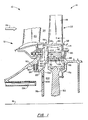
- Figure 1 is a cross sectional side view of the turbine section of a gas turbine engine illustrating the leakage of cooling air into the engine's main gaspath in the vicinity of the leading and trailing edges of a turbine blade platform.
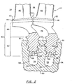
- Figure 2 is a view parallel to the engine axis taken essentially along the line 2-2 of Figure 1 showing two representative turbine blades retained in a rotor disk.
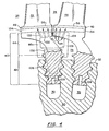
- Figure 3 is an enlarged view similar to figure 1 illustrating a cooling air conduit of the present invention formed by the rear face of a blade root and a groove in the abutting surface of a cover plate.
- Figure 4 is a view parallel to the engine axis showing the cover plate of Figure 3 in relation to the blade roots and rotor disk.
- Figure 5 is a side view of an alternative embodiment of an aft cover plate having fully bounded air passages.
- the turbine 10 of a gas turbine engine includes a nonrotating stator assembly 12 and a cooled rotor assembly 14 rotatable about a central longitudinal axis 16. Aerodynamically contoured vanes and blades such as representative vane 20 and blade 22 extend radially across a main gaspath 24. The vanes and blades cooperate to recover energy from high temperature combustion products 26 flowing through the gaspath. The recovery of energy from the combustion products spins the rotor assembly about the axis, and the rotary motion is conveyed to and powers a compressor, not shown.
- a rotor disk 30 has an outer rim 32 and a plurality of fir tree shaped attachment slots 34 extending from the outer rim to an inner rim 36.
- Each rotor blade 22 has a root 40 comprising a fir tree shaped attachment 42 and a neck 44. The fir tree attachment engages the attachment slots in the disk to radially retain the blades.
- Each blade also includes a platform 46 for defining the inner boundary of the main gaspath and an airfoil 48 extending across the gaspath.
- Each platform has a leading edge 56, a trailing edge 58, and lateral edges 60 extending from the leading edge to the trailing edge.
- each blade root When installed in the disk, the inner extremity 66 of each blade root cooperates with the sidewalls 68 of the attachment slots and the inner rim 36 to define a chamber 70.
- the outer rim 32, blade necks 44 and the platforms 46 of neighboring blades define a cavity 74 which may contain a damper, not shown, for damping undesirable vibration of the blades.
- the rotor assembly also includes circumferentially extending front and rear sideplates 76, 78 which bear against the blade roots to axially retain the blades in the attachment slots.
- the front sideplate includes a cylindrical seal land 80 and a pair of circumferentially extending wire seals 82 at the interface between the sideplate and the front face of the blade roots.
- a brush seal 90 is axially trapped between a shoulder 92 on the stator assembly and a seal retainer 94 so that the seal bristles 96 engage the seal land 80.
- a plurality of non-airtight windage covers 84 is secured to the front face of the disk.
- a plurality of rear cover plates 86 each having a fir tree shaped base 88 are retained adjacent to the blades in the disk attachment slots and are axially trapped between the blades and the rear sideplate.
- the disk, sideplate 76 and wire seals 82 bound an inner plenum 100.
- the seal retainer 94, sideplate 76, blade platforms 46 and the front faces of the blade roots bound an annular outer plenum 102.
- Cooling air is extracted from the compressor, not shown, and delivered to the turbine blades and vanes by way of one or more cooling air flowpaths.
- One of these flowpaths is bounded, in part, by the brush seal 90 and includes a series of nozzles 104 which inject cooling air in the vicinity of apertures 106 in the front sideplate.
- the flowpath extends through the apertures, inner plenum 100, and chamber 70 so that the cooling air is fed into passages 108 in each blade.
- the passages extend into the airfoils and the blade platforms so that cooling air flowing through the passages cools the blades and platforms.
- the cooling air may be discharged through cooling air holes, not shown, in the airfoils and platforms to form a protective cooling film over the blade and platform surfaces.
- leading edge leakage air 112 which flows radially outward, around the leading edges 56 of the blade platforms and discharges into the main gaspath with a significant radial velocity component.
- the radial velocity component of this leading edge leakage air interferes with the recovery of energy therefrom.
- trailing edge leakage air 114 which flows past the windage covers 84, rearward through cavity 74, and seeps radially outward along the interface between the rear cover plate 86 and the rear faces of the blade roots 40.
- the temperature of the combustion gases 26 is lower downstream of the blades than upstream of the blades.
- the combustion gases also have a radial temperature gradient which changes, due to a radial component of gas flow, as the gases flow axially past the blades 22.
- the gaspath temperature is higher in the vicinity of the platform trailing edges 58 than in the vicinity of the platform leading edges 56. Therefore, although the leading edge leakage air 112 flowing around the platform leading edges may provide some cooling thereof, it is more important to cool the trailing edges.
- the trailing edge leakage air 114 which seeps into the vicinity of the platform trailing edges is too insufficient in quantity and is too ineffectively directed to cool the trailing edges.
- a preferred rotor assembly includes a plurality of cover plates 86a each having at least one conduit 120 for intentionally drawing a large percentage of the leakage air from outer plenum 102 and impinging it against the trailing edges 58 of the blade platforms.
- conduits could be fully bounded passages 126 machined (for example by electrodischarge machining or laser drilling) through the interior of the cover plate as shown in Fig. 5.
- This alternative embodiment may provide superior cooling but is considerably more expensive to produce than a cover plate having the cast grooves of the preferred embodiment.
- the cover plate 86a also preferably includes a manifold 128 cast into the cover plate base for placing the intake end 130 of each conduit in flow communication with cavity 74.
- the manifold distributes the leakage air uniformly among the conduits and reduces the weight of the cover plate, an important consideration if the engine is used to power an aircraft. Additional weight savings arerealized by casting a weight reduction cavity 132 into the base 136 of the cover plate.
- the conduits 120 establish flow communication between cavities 74 and sub-gaspath region 134 radially inward of the platform trailing edges. Since the gas pressure is lower near the platform trailing edges than near the leading edges, leakage air from outer plenum 102 (Fig. 1) is discouraged from flowing radially outward and entering the gaspath unbeneficially in the vicinity of the platform leading edges. Instead, the pressure difference encourages most of the air to flow rearward, through cavities 74 and then radially outward through conduits 120. The leakage air is forcibly impinged on the platform trailing edges to augment the cooling provided by internal passages in the platform. As a result, the platform internal cooling flow may be reduced with an accompanying improvement in engine efficiency. In the limit, it may be possible to completely dispense with the internal cooling passages thereby considerably reducing the cost of manufacturing the blades and more than compensating for the minor expense of casting the grooves in the cover plate.
- the rotor assembly described above is characterized by a rear cover plate having conduits which divert most of the leakage air from plenum 102, leaving relatively little leakage air 112 to flow unproductively into the vicinity of the platform leading edges. Moreover, the conduits impinge the diverted leakage air against the blade platforms to improve the cooling thereof, thereby using the leakage air as beneficially as possible.
- the absence of conduits in a conventional rotor assembly causes the quantity of leading edge leakage air 112 to vastly exceed the quantity of trailing edge leakage air 114. As a result, the majority of the leakage air cools the leading edge of the platform even though the trailing edge is the region exposed to higher temperatures.
- the invention therefore redirects turbine cooling air, which has leaked out of a cooling air flowpath, and uses the redirected leakage air for cooling a component exposed to the hot gases flowing through the engine's main gaspath.
- the invention further accomplishes the redirection and beneficial use of the leakage air while minimizing the complexity and cost of the engine.
Landscapes
- Engineering & Computer Science (AREA)
- Mechanical Engineering (AREA)
- General Engineering & Computer Science (AREA)
- Turbine Rotor Nozzle Sealing (AREA)
Abstract
Description
- This invention relates to gas turbine engines and particularly to a cooled rotor assembly for such an engine in which cooling air, which inevitably escapes from a cooling air flowpath, is redirected to cool a surface exposed to hot gases flowing through the engine's main gaspath.
- In modern gas turbine engines, a quantity of compressed air is extracted from the engine's compressor section and routed to the engine's turbine section where it is used to cool those components, such as blades and vanes, which are exposed to hot combustion gases flowing through the engine's main gaspath. The cooling of turbine components enables the attainment of higher gaspath temperatures and therefore improves the power output of the engine. However the extraction of air from the compressor also introduces an inefficiency since the turbine cannot completely recover the energy expended to compress the air. It is, therefore, important to minimize the amount of cooling air extracted from the compressor and to fully utilize that air which is extracted.
- The cooling air is routed from the compressor to the turbine by way of one or more cooling air flowpaths. A typical cooling air flowpath includes a number of seals to minimize the leakage of cooling air from the flowpath and the accompanying efficiency penalty. Nevertheless, some cooling air inevitably leaks out of the flowpath. Since there is an efficiency penalty associated with having extracted this air from the compressor, it is desirable to put this leakage air to the best possible use and to do so without introducing significant complexity into the engine. It is equally desirable to avoid any significant increase in the cost of manufacturing the engine.
- For one specific model of a turbine engine which suffers from the above described leakage problem, cooling air escapes from a cooling air flowpath and enters a plenum in front of a turbine disk. The majority of this leakage air flows out of the plenum, around the leading edges of the turbine blade platforms and into the main gaspath. Although this leakage air may cool the platform leading edges, it is far more essential to cool the trailing edges. Thus, the leakage air is not used as productively as possible. Moreover, the leakage air flows into the gaspath with a significant radial velocity component rather than an axial velocity component which is required for the turbine to effectively recover energy from the air (thereby minimizing the inefficiency associated with having extracted the air from the compressor). A small portion of the leakage air also seeps into the gaspath in the vicinity of the trailing edges of the blade platforms. However this trailing edge leakage is ineffective for cooling the trailing edges since the quantity of air is small and its entry into the gaspath is unmanaged.
In broad terms, the present invention provides a rotor assembly for a gas turbine engine including: a rotor disk with a plurality of blade attachment slots; a plurality of rotor blades retained in the attachment slots, each rotor blade having a root and a platform; and cover means which abuts the blade roots characterised in that the cover means has at least one conduit for, in use, impinging leakage air against the trailing edges of the blade platforms. - According to the invention, cooling air, which has leaked out of a cooling air flowpath and into a plenum bounded in part by the front face of a rotor disk, is drawn out of the plenum and impinged upon the trailing edges of the turbine blade platforms.
- In one embodiment of the invention a plurality of turbine blades and rear cover plates are retained in the attachment slots of a turbine rotor disk. The cover plates abut the rear faces of the turbine blade roots and include a series of essentially radially oriented grooves. The grooves cooperate with the rear faces of the blade roots to define conduits in the cover plates. The conduits encourage air which has leaked into a plenum in front of the rotor disk to flow out of the plenum and rearward through cooling air cavities radially inward of the blade roots. The leakage air enters the conduits and is impinged onto the trailing edges of the turbine blade platforms.
- The primary advantage of the invention is that leakage air, which would otherwise flow unbeneficially into the gaspath in the vicinity of the platform leading edges, is diverted to the trailing edges where the need for cooling is greater. Moreover the leakage air is forcibly impinged upon the trailing edge to maximize the cooling effectiveness. Thus, the leakage air is used as productively and as beneficially as possible.
- A second advantage of the invention is the reduction or elimination of the need to cool the platform trailing edges by flowing leakage air through minute passages in the interior of the trailing edges and discharging that air as a cooling film over the trailing edge external surfaces. Any reduction in the quantity of this internal and film cooling air improves engine efficiency. In the event that internal and film cooling is rendered completely unnecessary, the internal cooling passages need not be installed, thereby saving considerable expense in the manufacture of the blades.
- A preferred embodiment of the invention will now be described, by way of example only, with reference to the accompanying drawings in which:
- Figure 1 is a cross sectional side view of the turbine section of a gas turbine engine illustrating the leakage of cooling air into the engine's main gaspath in the vicinity of the leading and trailing edges of a turbine blade platform.
- Figure 2 is a view parallel to the engine axis taken essentially along the line 2-2 of Figure 1 showing two representative turbine blades retained in a rotor disk.
- Figure 3 is an enlarged view similar to figure 1 illustrating a cooling air conduit of the present invention formed by the rear face of a blade root and a groove in the abutting surface of a cover plate.
- Figure 4 is a view parallel to the engine axis showing the cover plate of Figure 3 in relation to the blade roots and rotor disk.
- Figure 5 is a side view of an alternative embodiment of an aft cover plate having fully bounded air passages.
- Referring to figures 1 and 2, the
turbine 10 of a gas turbine engine includes anonrotating stator assembly 12 and a cooled rotor assembly 14 rotatable about a central longitudinal axis 16. Aerodynamically contoured vanes and blades such asrepresentative vane 20 andblade 22 extend radially across amain gaspath 24. The vanes and blades cooperate to recover energy from high temperature combustion products 26 flowing through the gaspath. The recovery of energy from the combustion products spins the rotor assembly about the axis, and the rotary motion is conveyed to and powers a compressor, not shown. - Examining the rotor assembly in more detail, a
rotor disk 30 has anouter rim 32 and a plurality of fir tree shapedattachment slots 34 extending from the outer rim to aninner rim 36. Eachrotor blade 22 has aroot 40 comprising a fir tree shapedattachment 42 and aneck 44. The fir tree attachment engages the attachment slots in the disk to radially retain the blades. Each blade also includes aplatform 46 for defining the inner boundary of the main gaspath and anairfoil 48 extending across the gaspath. Each platform has a leadingedge 56, atrailing edge 58, andlateral edges 60 extending from the leading edge to the trailing edge. - When installed in the disk, the
inner extremity 66 of each blade root cooperates with thesidewalls 68 of the attachment slots and theinner rim 36 to define achamber 70. In addition, theouter rim 32,blade necks 44 and theplatforms 46 of neighboring blades define acavity 74 which may contain a damper, not shown, for damping undesirable vibration of the blades. - The rotor assembly also includes circumferentially extending front and
rear sideplates cylindrical seal land 80 and a pair of circumferentially extendingwire seals 82 at the interface between the sideplate and the front face of the blade roots. Abrush seal 90 is axially trapped between ashoulder 92 on the stator assembly and aseal retainer 94 so that theseal bristles 96 engage theseal land 80. A plurality of non-airtight windage covers 84 is secured to the front face of the disk. A plurality ofrear cover plates 86 each having a fir tree shapedbase 88 are retained adjacent to the blades in the disk attachment slots and are axially trapped between the blades and the rear sideplate. The disk,sideplate 76 andwire seals 82 bound aninner plenum 100. Theseal retainer 94,sideplate 76,blade platforms 46 and the front faces of the blade roots bound an annularouter plenum 102. - In order to attain the highest possible operating temperatures, and therefore the maximum possible engine power, it is customary to cool those turbine components directly exposed to the hot combustion products. Cooling air is extracted from the compressor, not shown, and delivered to the turbine blades and vanes by way of one or more cooling air flowpaths. One of these flowpaths is bounded, in part, by the
brush seal 90 and includes a series ofnozzles 104 which inject cooling air in the vicinity ofapertures 106 in the front sideplate. The flowpath extends through the apertures,inner plenum 100, andchamber 70 so that the cooling air is fed intopassages 108 in each blade. The passages extend into the airfoils and the blade platforms so that cooling air flowing through the passages cools the blades and platforms. As is well known, the cooling air may be discharged through cooling air holes, not shown, in the airfoils and platforms to form a protective cooling film over the blade and platform surfaces. - A portion of the air discharged from
nozzles 104 inevitably leaks past thebrush seal 90, and intoouter plenum 102. Most of the air from the outer plenum is leadingedge leakage air 112 which flows radially outward, around the leadingedges 56 of the blade platforms and discharges into the main gaspath with a significant radial velocity component. The radial velocity component of this leading edge leakage air interferes with the recovery of energy therefrom. The balance of the air from the outer plenum is trailingedge leakage air 114 which flows past the windage covers 84, rearward throughcavity 74, and seeps radially outward along the interface between therear cover plate 86 and the rear faces of theblade roots 40. - On average, the temperature of the combustion gases 26 is lower downstream of the blades than upstream of the blades. The combustion gases also have a radial temperature gradient which changes, due to a radial component of gas flow, as the gases flow axially past the
blades 22. As a result, the gaspath temperature is higher in the vicinity of theplatform trailing edges 58 than in the vicinity of theplatform leading edges 56. Therefore, although the leadingedge leakage air 112 flowing around the platform leading edges may provide some cooling thereof, it is more important to cool the trailing edges. The trailingedge leakage air 114 which seeps into the vicinity of the platform trailing edges is too insufficient in quantity and is too ineffectively directed to cool the trailing edges. - Referring now to Figures 3-5 (and primarily to Figures 3 and 4), A preferred rotor assembly according to the present invention includes a plurality of
cover plates 86a each having at least oneconduit 120 for intentionally drawing a large percentage of the leakage air fromouter plenum 102 and impinging it against the trailingedges 58 of the blade platforms. In the preferred embodiment there are multiple conduits for impinging the air against the trailing edge from one lateral edge of the platform to the other and each conduit is formed by the rear face of ablade root 40 and a groove 122 (best seen in Fig. 4) cast into abuttingsurface 124 of thecover plate 86a. Alternatively, the conduits could be fully boundedpassages 126 machined (for example by electrodischarge machining or laser drilling) through the interior of the cover plate as shown in Fig. 5. This alternative embodiment may provide superior cooling but is considerably more expensive to produce than a cover plate having the cast grooves of the preferred embodiment. - The
cover plate 86a also preferably includes a manifold 128 cast into the cover plate base for placing theintake end 130 of each conduit in flow communication withcavity 74. The manifold distributes the leakage air uniformly among the conduits and reduces the weight of the cover plate, an important consideration if the engine is used to power an aircraft. Additional weight savings arerealized by casting aweight reduction cavity 132 into thebase 136 of the cover plate. - In operation, the
conduits 120 establish flow communication betweencavities 74 andsub-gaspath region 134 radially inward of the platform trailing edges. Since the gas pressure is lower near the platform trailing edges than near the leading edges, leakage air from outer plenum 102 (Fig. 1) is discouraged from flowing radially outward and entering the gaspath unbeneficially in the vicinity of the platform leading edges. Instead, the pressure difference encourages most of the air to flow rearward, throughcavities 74 and then radially outward throughconduits 120. The leakage air is forcibly impinged on the platform trailing edges to augment the cooling provided by internal passages in the platform. As a result, the platform internal cooling flow may be reduced with an accompanying improvement in engine efficiency. In the limit, it may be possible to completely dispense with the internal cooling passages thereby considerably reducing the cost of manufacturing the blades and more than compensating for the minor expense of casting the grooves in the cover plate. - In summary, the rotor assembly described above is characterized by a rear cover plate having conduits which divert most of the leakage air from
plenum 102, leaving relativelylittle leakage air 112 to flow unproductively into the vicinity of the platform leading edges. Moreover, the conduits impinge the diverted leakage air against the blade platforms to improve the cooling thereof, thereby using the leakage air as beneficially as possible. By contrast, the absence of conduits in a conventional rotor assembly causes the quantity of leadingedge leakage air 112 to vastly exceed the quantity of trailingedge leakage air 114. As a result, the majority of the leakage air cools the leading edge of the platform even though the trailing edge is the region exposed to higher temperatures. - It will be seen that in its preferred embodiments, the invention therefore redirects turbine cooling air, which has leaked out of a cooling air flowpath, and uses the redirected leakage air for cooling a component exposed to the hot gases flowing through the engine's main gaspath.
- The invention further accomplishes the redirection and beneficial use of the leakage air while minimizing the complexity and cost of the engine.
Claims (8)
- A rotor assembly for a gas turbine engine including:a rotor disk (30) with a plurality of blade attachment slots (34);a plurality of rotor blades (22) retained in the attachment slots, each rotor blade having a root (40) and a platform (46); andcover means (86a) which abuts the blade roots (40) characterised in that the cover means has at least one conduit (120;126) for, in use, impinging leakage air against the trailing edges (58) of the blade platforms (46).
- The rotor assembly of claim 1 wherein said cover means comprises a plurality of cover plates (86a) retained in the blade attachment slots (34) and abutting the blade roots (40), each cover plate (86a) having at least one conduit (120;126).
- The rotor assembly of claim 1 or 2 wherein said rotor disk (30) has an outer rim (32), the outer rim (32), blade roots (40) and blade piatforms (46) forming leakage cooling air cavities (74) in fluid communication with said conduits (120;126).
- The rotor assembly of claim 3 characterised in that the cover means (86a) includes manifolds (128) for placing the conduits (120;126) in flow communication with the cavities (74).
- The rotor assembly of any preceding claim wherein each of the conduits (120) is defined between the blade root (40) and the abutting surface (124) of the cover means (86a).
- The rotor assembly of claim 5 wherein each of the conduits (120) is defined by the rear face of one blade root (40) and a groove (122) in the abutting surface (124) of the cover means (86a).
- The rotor assembly of any of claims 1 to 4 wherein each of the conduits (126) is a fully bounded passage machined through the interior of the cover means (86a).
- A rotor assembly for a gas turbine engine including:a disk (30) with an outer rim (32), an inner rim (36) and a plurality of blade attachment slots (34) extending from the outer rim to the inner rim;a plurality of rotor blades (22), each blade having a root (40) and a platform (46) with a leading edge (56), a trailing edge (58) and lateral edges (60) extending from the leading edge to the trailing edge, the blades (22) being retained in the attachment slots (34) so that the outer rim, the blade roots, and the blade platforms define a plurality of cooling air cavities; anda plurality of cover plates (86a) retained in the blade slots (34), the cover plates (86a) having surfaces which abut the associated blade roots (40), the rotor assembly characterised in that each cover plate (86a) has at least one conduit (120;126) for drawing leakage air from a plenum (102) in front of the disk and for impinging the leakage air against the trailing edges (58) of the blade platforms (46).
Applications Claiming Priority (2)
| Application Number | Priority Date | Filing Date | Title |
|---|---|---|---|
| US08/631,506 US5800124A (en) | 1996-04-12 | 1996-04-12 | Cooled rotor assembly for a turbine engine |
| US631506 | 1996-04-12 |
Publications (3)
| Publication Number | Publication Date |
|---|---|
| EP0801208A2 true EP0801208A2 (en) | 1997-10-15 |
| EP0801208A3 EP0801208A3 (en) | 1999-07-14 |
| EP0801208B1 EP0801208B1 (en) | 2002-12-04 |
Family
ID=24531501
Family Applications (1)
| Application Number | Title | Priority Date | Filing Date |
|---|---|---|---|
| EP97302503A Expired - Lifetime EP0801208B1 (en) | 1996-04-12 | 1997-04-11 | Cooled rotor assembly for a turbine engine |
Country Status (4)
| Country | Link |
|---|---|
| US (1) | US5800124A (en) |
| EP (1) | EP0801208B1 (en) |
| JP (1) | JPH1047003A (en) |
| DE (1) | DE69717528T2 (en) |
Cited By (15)
| Publication number | Priority date | Publication date | Assignee | Title |
|---|---|---|---|---|
| EP1088963A3 (en) * | 1999-09-30 | 2003-12-03 | General Electric Company | Method and apparatus for purging turbine wheel cavities |
| EP1219778A3 (en) * | 2000-12-27 | 2004-01-07 | General Electric Company | Gas turbine blade with platform undercut |
| GB2408077A (en) * | 2003-10-31 | 2005-05-18 | Gen Electric | Methods and apparatus for cooling gas turbine rotor blades |
| US7186089B2 (en) | 2004-11-04 | 2007-03-06 | Siemens Power Generation, Inc. | Cooling system for a platform of a turbine blade |
| US7600972B2 (en) | 2003-10-31 | 2009-10-13 | General Electric Company | Methods and apparatus for cooling gas turbine engine rotor assemblies |
| EP2146055A1 (en) * | 2008-07-17 | 2010-01-20 | Ansaldo Energia S.P.A. | Sealing element for a gas turbine, a gas turbine including said sealing element and method for cooling said sealing element |
| EP1726784A3 (en) * | 2005-05-27 | 2010-06-16 | United Technologies Corporation | Gas turbine disk slots and gas turbine engine using same |
| EP2236758A1 (en) * | 2009-03-26 | 2010-10-06 | Siemens Aktiengesellschaft | Rotor blade system with sealing plates comprising ribs |
| WO2012030422A1 (en) * | 2010-08-31 | 2012-03-08 | General Electric Company | Tapered collet connection of rotor components |
| WO2014003958A1 (en) | 2012-06-29 | 2014-01-03 | United Technologies Corporation | Turbine blade platform with u-channel cooling holes |
| EP3034795A1 (en) * | 2014-12-17 | 2016-06-22 | Alstom Technology Ltd | Lock plate with radial grooves |
| EP3179032A1 (en) * | 2015-12-04 | 2017-06-14 | General Electric Company | Turbomachine blade cover plate having radial cooling groove |
| WO2021150418A1 (en) * | 2020-01-22 | 2021-07-29 | General Electric Company | Turbine rotor blade with angel wing seals with coolant transfer passage between adjacent wheel space portions by additive manufacture |
| US11220916B2 (en) | 2020-01-22 | 2022-01-11 | General Electric Company | Turbine rotor blade with platform with non-linear cooling passages by additive manufacture |
| US11492908B2 (en) | 2020-01-22 | 2022-11-08 | General Electric Company | Turbine rotor blade root with hollow mount with lattice support structure by additive manufacture |
Families Citing this family (33)
| Publication number | Priority date | Publication date | Assignee | Title |
|---|---|---|---|---|
| DE19705442A1 (en) * | 1997-02-13 | 1998-08-20 | Bmw Rolls Royce Gmbh | Turbine impeller disk with cooling air channels |
| DE69830026T2 (en) * | 1997-07-11 | 2005-09-29 | Rolls-Royce Plc | Lubrication of a gas turbine during takeoff |
| US6077035A (en) * | 1998-03-27 | 2000-06-20 | Pratt & Whitney Canada Corp. | Deflector for controlling entry of cooling air leakage into the gaspath of a gas turbine engine |
| US6179555B1 (en) * | 1998-10-06 | 2001-01-30 | Pratt & Whitney Canada Corp. | Sealing of T.O.B.I feed plenum |
| DE60045026D1 (en) * | 1999-09-24 | 2010-11-11 | Gen Electric | Gas turbine blade with impact cooled platform |
| DE19950109A1 (en) * | 1999-10-18 | 2001-04-19 | Asea Brown Boveri | Rotor for a gas turbine |
| EP1207268B1 (en) * | 2000-11-16 | 2005-02-09 | Siemens Aktiengesellschaft | Gas turbine blade and a process for manufacturing a gas turbine blade |
| WO2003052240A2 (en) * | 2001-12-14 | 2003-06-26 | Alstom Technology Ltd | Gas turbine system |
| US6832893B2 (en) | 2002-10-24 | 2004-12-21 | Pratt & Whitney Canada Corp. | Blade passive cooling feature |
| US7175386B2 (en) * | 2003-12-17 | 2007-02-13 | United Technologies Corporation | Airfoil with shaped trailing edge pedestals |
| GB0405679D0 (en) * | 2004-03-13 | 2004-04-21 | Rolls Royce Plc | A mounting arrangement for turbine blades |
| US7581923B2 (en) * | 2005-06-23 | 2009-09-01 | United Technologies Corporation | Gas turbine engine with purge air pump and guide |
| US7371044B2 (en) * | 2005-10-06 | 2008-05-13 | Siemens Power Generation, Inc. | Seal plate for turbine rotor assembly between turbine blade and turbine vane |
| US7387492B2 (en) * | 2005-12-20 | 2008-06-17 | General Electric Company | Methods and apparatus for cooling turbine blade trailing edges |
| FR2908153B1 (en) * | 2006-11-07 | 2011-05-13 | Snecma | DEVICE FOR HITCHING A DISTRIBUTOR (8) OF A TURBINE, TURBINE COMPRISING THEM, AND AN AIRCRAFT ENGINE WHICH IS EQUIPPED |
| US8152436B2 (en) * | 2008-01-08 | 2012-04-10 | Pratt & Whitney Canada Corp. | Blade under platform pocket cooling |
| US8727702B2 (en) * | 2008-05-30 | 2014-05-20 | United Technologies Corporation | Hoop snap spacer |
| US8292587B2 (en) * | 2008-12-18 | 2012-10-23 | Honeywell International Inc. | Turbine blade assemblies and methods of manufacturing the same |
| US8393869B2 (en) * | 2008-12-19 | 2013-03-12 | Solar Turbines Inc. | Turbine blade assembly including a damper |
| US8206119B2 (en) * | 2009-02-05 | 2012-06-26 | General Electric Company | Turbine coverplate systems |
| EP2233692A1 (en) * | 2009-03-27 | 2010-09-29 | Siemens Aktiengesellschaft | Axial turboengine rotor with rotor cooling |
| US8007230B2 (en) * | 2010-01-05 | 2011-08-30 | General Electric Company | Turbine seal plate assembly |
| US8459953B2 (en) * | 2010-01-19 | 2013-06-11 | General Electric Company | Seal plate and bucket retention pin assembly |
| US9022727B2 (en) * | 2010-11-15 | 2015-05-05 | Mtu Aero Engines Gmbh | Rotor for a turbo machine |
| US8876479B2 (en) | 2011-03-15 | 2014-11-04 | United Technologies Corporation | Damper pin |
| US8951014B2 (en) | 2011-03-15 | 2015-02-10 | United Technologies Corporation | Turbine blade with mate face cooling air flow |
| GB201113893D0 (en) * | 2011-08-12 | 2011-09-28 | Rolls Royce Plc | Oil mist separation in gas turbine engines |
| FR2995003B1 (en) * | 2012-09-03 | 2014-08-15 | Snecma | ROTOR OF TURBINE FOR A TURBOMACHINE |
| US9605552B2 (en) | 2013-06-10 | 2017-03-28 | General Electric Company | Non-integral segmented angel-wing seal |
| WO2015020931A2 (en) * | 2013-08-09 | 2015-02-12 | United Technologies Corporation | Cover plate assembly for a gas turbine engine |
| EP3044423B1 (en) | 2013-09-12 | 2020-04-29 | United Technologies Corporation | Disk outer rim seal |
| US10378379B2 (en) | 2015-08-27 | 2019-08-13 | General Electric Company | Gas turbine engine cooling air manifolds with spoolies |
| US11021962B2 (en) * | 2018-08-22 | 2021-06-01 | Raytheon Technologies Corporation | Turbulent air reducer for a gas turbine engine |
Family Cites Families (16)
| Publication number | Priority date | Publication date | Assignee | Title |
|---|---|---|---|---|
| US2988325A (en) * | 1957-07-18 | 1961-06-13 | Rolls Royce | Rotary fluid machine with means supplying fluid to rotor blade passages |
| BE792286A (en) * | 1971-12-06 | 1973-03-30 | Gen Electric | BOLTLESS AUBA RETAINER FOR TURBOMACHIN ROTOR |
| US3834831A (en) * | 1973-01-23 | 1974-09-10 | Westinghouse Electric Corp | Blade shank cooling arrangement |
| US3989410A (en) * | 1974-11-27 | 1976-11-02 | General Electric Company | Labyrinth seal system |
| US4265590A (en) * | 1978-05-20 | 1981-05-05 | Rolls-Royce Limited | Cooling air supply arrangement for a gas turbine engine |
| US4348157A (en) * | 1978-10-26 | 1982-09-07 | Rolls-Royce Limited | Air cooled turbine for a gas turbine engine |
| GB2095763A (en) * | 1980-12-29 | 1982-10-06 | Rolls Royce | Enhancing turbine blade coolant seal force |
| US4439107A (en) * | 1982-09-16 | 1984-03-27 | United Technologies Corporation | Rotor blade cooling air chamber |
| US4626169A (en) * | 1983-12-13 | 1986-12-02 | United Technologies Corporation | Seal means for a blade attachment slot of a rotor assembly |
| US4505640A (en) * | 1983-12-13 | 1985-03-19 | United Technologies Corporation | Seal means for a blade attachment slot of a rotor assembly |
| GB8705216D0 (en) * | 1987-03-06 | 1987-04-08 | Rolls Royce Plc | Rotor assembly |
| US4820116A (en) * | 1987-09-18 | 1989-04-11 | United Technologies Corporation | Turbine cooling for gas turbine engine |
| US5143512A (en) * | 1991-02-28 | 1992-09-01 | General Electric Company | Turbine rotor disk with integral blade cooling air slots and pumping vanes |
| US5211533A (en) * | 1991-10-30 | 1993-05-18 | General Electric Company | Flow diverter for turbomachinery seals |
| US5310319A (en) * | 1993-01-12 | 1994-05-10 | United Technologies Corporation | Free standing turbine disk sideplate assembly |
| US5415526A (en) * | 1993-11-19 | 1995-05-16 | Mercadante; Anthony J. | Coolable rotor assembly |
-
1996
- 1996-04-12 US US08/631,506 patent/US5800124A/en not_active Expired - Lifetime
-
1997
- 1997-04-11 DE DE69717528T patent/DE69717528T2/en not_active Expired - Lifetime
- 1997-04-11 EP EP97302503A patent/EP0801208B1/en not_active Expired - Lifetime
- 1997-04-14 JP JP9095633A patent/JPH1047003A/en not_active Ceased
Cited By (28)
| Publication number | Priority date | Publication date | Assignee | Title |
|---|---|---|---|---|
| EP1088963A3 (en) * | 1999-09-30 | 2003-12-03 | General Electric Company | Method and apparatus for purging turbine wheel cavities |
| EP1219778A3 (en) * | 2000-12-27 | 2004-01-07 | General Electric Company | Gas turbine blade with platform undercut |
| US7600972B2 (en) | 2003-10-31 | 2009-10-13 | General Electric Company | Methods and apparatus for cooling gas turbine engine rotor assemblies |
| US6984112B2 (en) | 2003-10-31 | 2006-01-10 | General Electric Company | Methods and apparatus for cooling gas turbine rotor blades |
| GB2408077B (en) * | 2003-10-31 | 2007-08-08 | Gen Electric | Methods and apparatus for cooling gas turbine rotor blades |
| CN1611748B (en) * | 2003-10-31 | 2010-09-08 | 通用电气公司 | Gas turbine engine rotor blade |
| EP1528224A3 (en) * | 2003-10-31 | 2012-06-13 | General Electric Company | Method and apparatus for cooling gas turbine engine rotor blade |
| GB2408077A (en) * | 2003-10-31 | 2005-05-18 | Gen Electric | Methods and apparatus for cooling gas turbine rotor blades |
| US7186089B2 (en) | 2004-11-04 | 2007-03-06 | Siemens Power Generation, Inc. | Cooling system for a platform of a turbine blade |
| EP1726784A3 (en) * | 2005-05-27 | 2010-06-16 | United Technologies Corporation | Gas turbine disk slots and gas turbine engine using same |
| EP2146055B2 (en) † | 2008-07-17 | 2022-01-19 | Ansaldo Energia S.P.A. | Sealing element for a gas turbine, a gas turbine including said sealing element and method for cooling said sealing element |
| EP2146055A1 (en) * | 2008-07-17 | 2010-01-20 | Ansaldo Energia S.P.A. | Sealing element for a gas turbine, a gas turbine including said sealing element and method for cooling said sealing element |
| EP2236758A1 (en) * | 2009-03-26 | 2010-10-06 | Siemens Aktiengesellschaft | Rotor blade system with sealing plates comprising ribs |
| WO2012030422A1 (en) * | 2010-08-31 | 2012-03-08 | General Electric Company | Tapered collet connection of rotor components |
| US8608436B2 (en) | 2010-08-31 | 2013-12-17 | General Electric Company | Tapered collet connection of rotor components |
| WO2014003958A1 (en) | 2012-06-29 | 2014-01-03 | United Technologies Corporation | Turbine blade platform with u-channel cooling holes |
| US9243500B2 (en) | 2012-06-29 | 2016-01-26 | United Technologies Corporation | Turbine blade platform with U-channel cooling holes |
| EP2867501A4 (en) * | 2012-06-29 | 2015-07-08 | United Technologies Corp | TURBINE BLADE PLATFORM COMPRISING U-CHANNEL CHILL HOLES |
| EP3034795A1 (en) * | 2014-12-17 | 2016-06-22 | Alstom Technology Ltd | Lock plate with radial grooves |
| US10132172B2 (en) | 2014-12-17 | 2018-11-20 | Ansaldo Energia Switzerland AG | Arrangement of a rotor and at least a blade |
| EP3179032A1 (en) * | 2015-12-04 | 2017-06-14 | General Electric Company | Turbomachine blade cover plate having radial cooling groove |
| CN106968719A (en) * | 2015-12-04 | 2017-07-21 | 通用电气公司 | Turbine blade cover plate with radial direction cooling groove |
| US10066485B2 (en) | 2015-12-04 | 2018-09-04 | General Electric Company | Turbomachine blade cover plate having radial cooling groove |
| CN106968719B (en) * | 2015-12-04 | 2021-05-28 | 通用电气公司 | Turbine blade cover with radial cooling grooves |
| WO2021150418A1 (en) * | 2020-01-22 | 2021-07-29 | General Electric Company | Turbine rotor blade with angel wing seals with coolant transfer passage between adjacent wheel space portions by additive manufacture |
| US11220916B2 (en) | 2020-01-22 | 2022-01-11 | General Electric Company | Turbine rotor blade with platform with non-linear cooling passages by additive manufacture |
| US11248471B2 (en) | 2020-01-22 | 2022-02-15 | General Electric Company | Turbine rotor blade with angel wing with coolant transfer passage between adjacent wheel space portions by additive manufacture |
| US11492908B2 (en) | 2020-01-22 | 2022-11-08 | General Electric Company | Turbine rotor blade root with hollow mount with lattice support structure by additive manufacture |
Also Published As
| Publication number | Publication date |
|---|---|
| EP0801208B1 (en) | 2002-12-04 |
| JPH1047003A (en) | 1998-02-17 |
| EP0801208A3 (en) | 1999-07-14 |
| US5800124A (en) | 1998-09-01 |
| DE69717528D1 (en) | 2003-01-16 |
| DE69717528T2 (en) | 2003-08-14 |
Similar Documents
| Publication | Publication Date | Title |
|---|---|---|
| EP0801208B1 (en) | Cooled rotor assembly for a turbine engine | |
| EP1262634B1 (en) | Integral nozzle and shroud segment | |
| EP0974733B1 (en) | Turbine nozzle having purge air circuit | |
| EP0702748B1 (en) | Rotor blade with cooled integral platform | |
| EP1921292B1 (en) | Compound tubine cooled engine | |
| EP0916811B1 (en) | Ribbed turbine blade tip | |
| EP0789806B1 (en) | Gas turbine blade with a cooled platform | |
| EP0777818B1 (en) | Gas turbine blade with cooled platform | |
| US6499950B2 (en) | Cooling circuit for a gas turbine bucket and tip shroud | |
| EP1205636B1 (en) | Turbine blade for a gas turbine and method of cooling said blade | |
| US7322797B2 (en) | Damper cooled turbine blade | |
| US8240981B2 (en) | Turbine airfoil with platform cooling | |
| US6468031B1 (en) | Nozzle cavity impingement/area reduction insert | |
| EP1526251A1 (en) | Turbine nozzle cooling configuration | |
| US6174133B1 (en) | Coolable airfoil | |
| CA2649035C (en) | Blade under platform pocket cooling | |
| EP1225304A2 (en) | Nozzle fillet backside cooling | |
| WO1994018436A1 (en) | Coolable outer air seal assembly for a gas turbine engine | |
| CA2548692A1 (en) | Blade neck fluid seal |
Legal Events
| Date | Code | Title | Description |
|---|---|---|---|
| PUAI | Public reference made under article 153(3) epc to a published international application that has entered the european phase |
Free format text: ORIGINAL CODE: 0009012 |
|
| AK | Designated contracting states |
Kind code of ref document: A2 Designated state(s): DE FR GB |
|
| PUAL | Search report despatched |
Free format text: ORIGINAL CODE: 0009013 |
|
| AK | Designated contracting states |
Kind code of ref document: A3 Designated state(s): DE FR GB |
|
| RIC1 | Information provided on ipc code assigned before grant |
Free format text: 6F 01D 5/08 A, 6F 01D 5/30 B |
|
| 17P | Request for examination filed |
Effective date: 19990910 |
|
| 17Q | First examination report despatched |
Effective date: 20010821 |
|
| GRAG | Despatch of communication of intention to grant |
Free format text: ORIGINAL CODE: EPIDOS AGRA |
|
| GRAG | Despatch of communication of intention to grant |
Free format text: ORIGINAL CODE: EPIDOS AGRA |
|
| GRAH | Despatch of communication of intention to grant a patent |
Free format text: ORIGINAL CODE: EPIDOS IGRA |
|
| GRAH | Despatch of communication of intention to grant a patent |
Free format text: ORIGINAL CODE: EPIDOS IGRA |
|
| GRAA | (expected) grant |
Free format text: ORIGINAL CODE: 0009210 |
|
| AK | Designated contracting states |
Kind code of ref document: B1 Designated state(s): DE FR GB |
|
| REG | Reference to a national code |
Ref country code: GB Ref legal event code: FG4D |
|
| REF | Corresponds to: |
Ref document number: 69717528 Country of ref document: DE Date of ref document: 20030116 |
|
| ET | Fr: translation filed | ||
| PLBE | No opposition filed within time limit |
Free format text: ORIGINAL CODE: 0009261 |
|
| STAA | Information on the status of an ep patent application or granted ep patent |
Free format text: STATUS: NO OPPOSITION FILED WITHIN TIME LIMIT |
|
| 26N | No opposition filed |
Effective date: 20030905 |
|
| REG | Reference to a national code |
Ref country code: FR Ref legal event code: PLFP Year of fee payment: 20 |
|
| PGFP | Annual fee paid to national office [announced via postgrant information from national office to epo] |
Ref country code: FR Payment date: 20160323 Year of fee payment: 20 Ref country code: GB Payment date: 20160324 Year of fee payment: 20 |
|
| PGFP | Annual fee paid to national office [announced via postgrant information from national office to epo] |
Ref country code: DE Payment date: 20160321 Year of fee payment: 20 |
|
| REG | Reference to a national code |
Ref country code: DE Ref legal event code: R071 Ref document number: 69717528 Country of ref document: DE |
|
| REG | Reference to a national code |
Ref country code: FR Ref legal event code: CA Effective date: 20170324 |
|
| REG | Reference to a national code |
Ref country code: GB Ref legal event code: PE20 Expiry date: 20170410 |
|
| PG25 | Lapsed in a contracting state [announced via postgrant information from national office to epo] |
Ref country code: GB Free format text: LAPSE BECAUSE OF EXPIRATION OF PROTECTION Effective date: 20170410 |