EP0801175A2 - Underwater cable burial machine using single cable for towing and lifting - Google Patents
Underwater cable burial machine using single cable for towing and lifting Download PDFInfo
- Publication number
- EP0801175A2 EP0801175A2 EP97103874A EP97103874A EP0801175A2 EP 0801175 A2 EP0801175 A2 EP 0801175A2 EP 97103874 A EP97103874 A EP 97103874A EP 97103874 A EP97103874 A EP 97103874A EP 0801175 A2 EP0801175 A2 EP 0801175A2
- Authority
- EP
- European Patent Office
- Prior art keywords
- cable
- towing
- machine
- retractable
- underwater
- Prior art date
- Legal status (The legal status is an assumption and is not a legal conclusion. Google has not performed a legal analysis and makes no representation as to the accuracy of the status listed.)
- Granted
Links
Images
Classifications
-
- E—FIXED CONSTRUCTIONS
- E02—HYDRAULIC ENGINEERING; FOUNDATIONS; SOIL SHIFTING
- E02F—DREDGING; SOIL-SHIFTING
- E02F5/00—Dredgers or soil-shifting machines for special purposes
- E02F5/02—Dredgers or soil-shifting machines for special purposes for digging trenches or ditches
- E02F5/10—Dredgers or soil-shifting machines for special purposes for digging trenches or ditches with arrangements for reinforcing trenches or ditches; with arrangements for making or assembling conduits or for laying conduits or cables
- E02F5/104—Dredgers or soil-shifting machines for special purposes for digging trenches or ditches with arrangements for reinforcing trenches or ditches; with arrangements for making or assembling conduits or for laying conduits or cables for burying conduits or cables in trenches under water
- E02F5/106—Dredgers or soil-shifting machines for special purposes for digging trenches or ditches with arrangements for reinforcing trenches or ditches; with arrangements for making or assembling conduits or for laying conduits or cables for burying conduits or cables in trenches under water using ploughs, coulters, rippers
Definitions
- the present invention relates to underwater cable burial machines.
- the invention relates to an underwater cable burial machine which uses a single cable for both towing and lifting.
- Underwater burial machines are used to bury communications cables in the sea bottom in an effort to protect the cables from damage. These machines plow a groove in the seabed beneath a body of water, and they simultaneously lay a cable into the groove which they have plowed. Burial machines use at least one plow blade to cut a groove into the seabed immediately in front of a cable laying mechanism. The cable is then placed into the groove thus formed in order that it will be somewhat beneath the surface of the seabed. After the cable has been laid into the groove, water pressure and underwater currents eventually cause the vertical walls of the groove to collapse and move sand and soil into the groove, thereby covering the cable and assisting in the overall burial operation.
- the burial machines Periodically the burial machines must be returned to the surface for maintenance or for transportation from a site. While it is preferable to be able to minimize the number of cables in the water, in order to avoid damage to the communications cable which is being laid, and to avoid cables becoming entangled, in order to raise the machines of the prior art to the surface, more than one cable has been needed.
- the machines used complicated schemes by which they could be towed by a combination towing/umbilical cable, and then lifted by that cable when a relatively large yoke was pivoted from the front of the machine (towing position) to the a point above the machine (lifting position). Such arrangements were unwieldy, and they increased the likelihood of damage to or entanglement of the cables or damage to the machine.
- a new design approach has been disclosed which solves the problem of being able to both tow and lift a cable burial machine using a single cable.
- the new design uses a relatively short, strong steel retractable cable which is attached to a retraction mechanism on the cable burial machine.
- the retractable cable passes through a cable guide which is mounted on the top of the cable burial machine, over the cable burial machine's center of gravity.
- the other end of the retractable cable is attached to the towing/umbilical cable at a point which is at least as far away from the towing point on the machine as the cable guide is from the towing point.
- connection point distance from the towing point is important, in that it will be necessary to retract the connection point to the cable guide, so if the retractable cable is attached any to the towing/umbilical cable, any closer than the towing/umbilical cable is connected to the towing point than it will not be possible to bring the connection point back to the cable guide.
- the retractable cable When lifting of the cable burial machine is desired, the retractable cable is pulled back through the cable guide by the retraction mechanism, pulling the towing/umbilical cable with it.
- the towing/umbilical cable When both cables have been withdrawn to the cable guide, the towing/umbilical cable will be over the center of gravity of the cable burial machine, so it can be used to lift the cable burial machine to the surface.
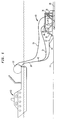
- FIG. 1 a simplified side view of a cable laying machine 10 employing the single cable lifting and towing system of the present invention is shown.
- the cable laying machine 10 is mounted on a sea sled 12 which is being towed along the seabed 14 by a surface vessel 16.
- the towing is accomplished by means of a combination towing/umbilical cable 18.
- a communications cable 20 is unspooled from a spool 22 on the vessel 16.
- a plow 24 cuts a groove 26 in the seabed 14, and the communications cable 20 is laid into the groove 26 by cable laying apparatus 28 which is located on the rear of a carriage 30 which is fixed to the sled 14 using a four bar linkage 32.
- the four bar linkage 32 allows the carriage 30 to be moved up and down relative to the sled 12. This permits the plow 24 and cable laying apparatus 28, both of which are attached to the carriage 30, and both of which are shown to extend through the flat bottom of the sled 12, to be moved up and down relative to the bottom of the sled 12.
- the four bar linkage 32 allows the plow 24 and the cable laying apparatus 28 to be moved up above the bottom of the sled 12 when the sled 12 is recovered onto the deck of the vessel 16 for transportation or maintenance.
- the four bar linkage 32 can be used to adjust the depth of the groove 26 in the event that that becomes necessary due to the makeup of the seabed 14, i.e., if a rock layer is encountered below the surface of the seabed 14 at a depth which is less than the normal cable laying depth.
- the four bar linkage 32 could be adjusted using hydraulic cylinders (not shown) so that the plow teeth only extended somewhat less than ten inches below the seabed 14, thereby preventing damage to the teeth while allowing the burial operation to continue.
- the combination towing/umbilical cable 18 is used to both tow the sled 12, and to carry hydraulic fluid and electrical signals between the vessel 16 and the sled 12.
- the present invention makes use of a retractable cable 34, a cable guide 36 mounted on top of the carriage 30 at the center of gravity of the burial machine 10, and a retraction mechanism 38 (See FIGS. 3 and 4), which is illustrated by the drum 40, to which one end of the retractable cable 34 is attached.
- retractable cable 34 is attached to the towing/umbilical cable 18 at a point 42 which is at least as far from the towing point 44 on the sled 12 as the towing point 44 is from the cable guide 36.
- the retraction mechanism 38 is operated to pull the retractable cable 34, and the attachment point 42 (i.e., where the retractable cable 34 connects to the towing/umbilical cable 18) back to the cable guide 36.
- the retractable cable 34 will be wound unto the drum 40 (See FIGS. 3 and 4), so it is not visible in FIG. 2.
- the towing/umbilical cable 18 can be used to raise the burial machine 10 from above its center of gravity, up to the surface vessel 16.
- the burial machine 10 will remain horizontal as it is lifted without any need for any type of complicated towing hardware, or without the need for multiple cables extending up to the surface vessel 16.
- the retractable cable could be well under one hundred feet long, no matter how deep the cable burying operation is being conducted.
- the cable guide 36 is shown to be a toroidal structure. While other shapes may be used, it is important that a shape be selected which does not cause chafing to the retractable cable 34, or to the towing/umbilical cable 18.
- the cable guide 36 is preferably mounted on a plate 46 which includes means for adjusting its location relative to the carriage 30 (See FIGS. 1 and 2), in order to insure that the cable guide 36 is over the center of gravity of the cable burial machine 10.
- the plate 46 is bolted to arms 48, 50 which are attached to the carriage 30. Accordingly, by changing the location of the bolts (not shown) in the elongated holes 52, the cable guide 36 may be selectively moved over the center of gravity of the cable burial machine 10.
- the cable drum 40 which receives and dispenses the retractable cable 36 is also shown in FIGS. 3 and 4, and a motor 56 which is preferably driven by hydraulic means (not shown) is connected to the cable drum 40 by means of an appropriate, reversible drive mechanism 58, which may be a worm gear, a chain drive, or a similar means for transmitting power from the motor 56 to the drum 54.
- an appropriate, reversible drive mechanism 58 which may be a worm gear, a chain drive, or a similar means for transmitting power from the motor 56 to the drum 54.
- the combination of the drum 54, the motor 56, and the drive mechanism 58 make up the cable retraction mechanism 38, shown in FIGS. 1 and 2.
Landscapes
- Engineering & Computer Science (AREA)
- Mechanical Engineering (AREA)
- Mining & Mineral Resources (AREA)
- Civil Engineering (AREA)
- General Engineering & Computer Science (AREA)
- Structural Engineering (AREA)
- Laying Of Electric Cables Or Lines Outside (AREA)
- Electric Cable Installation (AREA)
Abstract
Description
- The present invention relates to underwater cable burial machines. In particular, the invention relates to an underwater cable burial machine which uses a single cable for both towing and lifting.
- Underwater burial machines are used to bury communications cables in the sea bottom in an effort to protect the cables from damage. These machines plow a groove in the seabed beneath a body of water, and they simultaneously lay a cable into the groove which they have plowed. Burial machines use at least one plow blade to cut a groove into the seabed immediately in front of a cable laying mechanism. The cable is then placed into the groove thus formed in order that it will be somewhat beneath the surface of the seabed. After the cable has been laid into the groove, water pressure and underwater currents eventually cause the vertical walls of the groove to collapse and move sand and soil into the groove, thereby covering the cable and assisting in the overall burial operation.
- Periodically the burial machines must be returned to the surface for maintenance or for transportation from a site. While it is preferable to be able to minimize the number of cables in the water, in order to avoid damage to the communications cable which is being laid, and to avoid cables becoming entangled, in order to raise the machines of the prior art to the surface, more than one cable has been needed. Alternatively, the machines used complicated schemes by which they could be towed by a combination towing/umbilical cable, and then lifted by that cable when a relatively large yoke was pivoted from the front of the machine (towing position) to the a point above the machine (lifting position). Such arrangements were unwieldy, and they increased the likelihood of damage to or entanglement of the cables or damage to the machine.
- In view of the foregoing problems which were not solved by the cable burial machines of the prior art, an improved cable burial machine which uses single cable for both lifting and towing, but which avoided the problems of the prior art would be desirable.
- In accordance with the present invention, a new design approach has been disclosed which solves the problem of being able to both tow and lift a cable burial machine using a single cable. The new design uses a relatively short, strong steel retractable cable which is attached to a retraction mechanism on the cable burial machine. The retractable cable passes through a cable guide which is mounted on the top of the cable burial machine, over the cable burial machine's center of gravity. The other end of the retractable cable is attached to the towing/umbilical cable at a point which is at least as far away from the towing point on the machine as the cable guide is from the towing point. The connection point distance from the towing point is important, in that it will be necessary to retract the connection point to the cable guide, so if the retractable cable is attached any to the towing/umbilical cable, any closer than the towing/umbilical cable is connected to the towing point than it will not be possible to bring the connection point back to the cable guide.
- When lifting of the cable burial machine is desired, the retractable cable is pulled back through the cable guide by the retraction mechanism, pulling the towing/umbilical cable with it. When both cables have been withdrawn to the cable guide, the towing/umbilical cable will be over the center of gravity of the cable burial machine, so it can be used to lift the cable burial machine to the surface.
- In the Drawing:
- FIG. 1 is a side view illustrating the improved cable laying mechanism of the present invention on a cable burial machine being towed by a surface vessel in a cable laying operation;
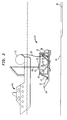
- FIG. 2 is a side view illustrating the improved cable laying mechanism of the present invention illustrating the manner in which the towing cable is able to lift the cable burial machine from a point above the center of gravity of the towing machine;
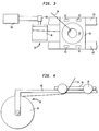
- FIG. 3 top view of the retraction mechanism and the cable guide of the present invention; and
- FIG. 4 is a side view of the retraction mechanism and the cable guide of the present invention.
- Referring to FIG. 1, a simplified side view of a
cable laying machine 10 employing the single cable lifting and towing system of the present invention is shown. Thecable laying machine 10 is mounted on asea sled 12 which is being towed along theseabed 14 by asurface vessel 16. The towing is accomplished by means of a combination towing/umbilical cable 18. - During the towing operation, a
communications cable 20 is unspooled from aspool 22 on thevessel 16. As thesled 12 is pulled forward, aplow 24 cuts agroove 26 in theseabed 14, and thecommunications cable 20 is laid into thegroove 26 bycable laying apparatus 28 which is located on the rear of acarriage 30 which is fixed to thesled 14 using a fourbar linkage 32. As will be understood by those skilled in the art, the fourbar linkage 32 allows thecarriage 30 to be moved up and down relative to thesled 12. This permits theplow 24 andcable laying apparatus 28, both of which are attached to thecarriage 30, and both of which are shown to extend through the flat bottom of thesled 12, to be moved up and down relative to the bottom of thesled 12. The fourbar linkage 32 allows theplow 24 and thecable laying apparatus 28 to be moved up above the bottom of thesled 12 when thesled 12 is recovered onto the deck of thevessel 16 for transportation or maintenance. In addition, the fourbar linkage 32 can be used to adjust the depth of thegroove 26 in the event that that becomes necessary due to the makeup of theseabed 14, i.e., if a rock layer is encountered below the surface of theseabed 14 at a depth which is less than the normal cable laying depth. By way of example, if the normal cable laying depth was twelve inches, and a rock layer was encountered ten inches below the surface of theseabed 14, then the fourbar linkage 32 could be adjusted using hydraulic cylinders (not shown) so that the plow teeth only extended somewhat less than ten inches below theseabed 14, thereby preventing damage to the teeth while allowing the burial operation to continue. - As will be understood by those skilled in the art, the combination towing/
umbilical cable 18 is used to both tow thesled 12, and to carry hydraulic fluid and electrical signals between thevessel 16 and thesled 12. - With continued reference to FIG. 1, the present invention makes use of a
retractable cable 34, acable guide 36 mounted on top of thecarriage 30 at the center of gravity of theburial machine 10, and a retraction mechanism 38 (See FIGS. 3 and 4), which is illustrated by thedrum 40, to which one end of theretractable cable 34 is attached. - The other end of
retractable cable 34 is attached to the towing/umbilical cable 18 at apoint 42 which is at least as far from thetowing point 44 on thesled 12 as thetowing point 44 is from thecable guide 36. - Referring to FIG. 2, when recovery of the
sled 10 onto thesurface vessel 16 is desired, theretraction mechanism 38 is operated to pull theretractable cable 34, and the attachment point 42 (i.e., where theretractable cable 34 connects to the towing/umbilical cable 18) back to thecable guide 36. When thecables cable guide 36, so that theattachment point 42 is at thecable guide 36, theretractable cable 34 will be wound unto the drum 40 (See FIGS. 3 and 4), so it is not visible in FIG. 2. In this position, the towing/umbilical cable 18 can be used to raise theburial machine 10 from above its center of gravity, up to thesurface vessel 16. As the lifting of theburial machine 10 will be from above the center of gravity of theburial machine 10, theburial machine 10 will remain horizontal as it is lifted without any need for any type of complicated towing hardware, or without the need for multiple cables extending up to thesurface vessel 16. By way of example, for asled 10 which is on the order of twenty feet long, the retractable cable could be well under one hundred feet long, no matter how deep the cable burying operation is being conducted. - Referring now to FIGS. 3 and 4, the
cable guide 36 is shown to be a toroidal structure. While other shapes may be used, it is important that a shape be selected which does not cause chafing to theretractable cable 34, or to the towing/umbilical cable 18. - The
cable guide 36 is preferably mounted on aplate 46 which includes means for adjusting its location relative to the carriage 30 (See FIGS. 1 and 2), in order to insure that thecable guide 36 is over the center of gravity of thecable burial machine 10. In the preferred embodiment of the invention, theplate 46 is bolted toarms carriage 30. Accordingly, by changing the location of the bolts (not shown) in theelongated holes 52, thecable guide 36 may be selectively moved over the center of gravity of thecable burial machine 10. - The
cable drum 40 which receives and dispenses theretractable cable 36 is also shown in FIGS. 3 and 4, and amotor 56 which is preferably driven by hydraulic means (not shown) is connected to thecable drum 40 by means of an appropriate,reversible drive mechanism 58, which may be a worm gear, a chain drive, or a similar means for transmitting power from themotor 56 to the drum 54. The combination of the drum 54, themotor 56, and thedrive mechanism 58, make up thecable retraction mechanism 38, shown in FIGS. 1 and 2. - As will be obvious to those skilled in the art, numerous changes can be made to the preferred embodiment of the invention without departing from the spirit or scope of the invention described herein.
Claims (8)
- An underwater cable burial machine which uses a single towing cable for towing and lifting comprises:(a) a retractable cable;(b) a cable retraction mechanism mounted on said burial machine, said cable retraction mechanism being attached to said retractable cable;(c) cable guide means for feeding said retractable cable over the center of gravity of said cable burial machine; and(d) means for attaching the end of said retractable cable which is remote from said cable retraction mechanism to said towing cable.
- The underwater cable burial machine of Claim 1 further comprising means for adjusting the location of said guide means, whereby said guide means may be repositioned over the center of gravity of said machine.
- The underwater cable burial machine of Claim 2 wherein said towing cable is attached to a towing point at the front of said machine, and said retractable cable is attached to said towing cable at a point which is at least as far from said towing point as said cable guide is from said towing point.
- The underwater cable burial machine of Claim 3 wherein said retraction mechanism includes a drum for collecting and dispensing said retractable cable.
- The underwater cable burial machine of Claim 4 wherein said retraction mechanism further comprises a drive motor for reversibly turning said drum to selectively retrieve or dispense said retractable cable.
- The underwater cable burial machine of Claim 5 wherein said motor is hydraulically driven.
- The underwater cable burial machine of Claim 6 wherein said retraction mechanism further comprises a worm gear for transmitting power from said motor to said drum.
- The underwater cable burial machine of Claim 6 wherein said retraction mechanism further comprises a chain drive for transmitting power from said motor to said drum.
Applications Claiming Priority (2)
| Application Number | Priority Date | Filing Date | Title |
|---|---|---|---|
| US629122 | 1996-04-08 | ||
| US08/629,122 US5707174A (en) | 1996-04-08 | 1996-04-08 | Underwater cable burial machine using a single cable for towing and lifting |
Publications (3)
| Publication Number | Publication Date |
|---|---|
| EP0801175A2 true EP0801175A2 (en) | 1997-10-15 |
| EP0801175A3 EP0801175A3 (en) | 1998-11-11 |
| EP0801175B1 EP0801175B1 (en) | 2002-10-23 |
Family
ID=24521670
Family Applications (1)
| Application Number | Title | Priority Date | Filing Date |
|---|---|---|---|
| EP97103874A Expired - Lifetime EP0801175B1 (en) | 1996-04-08 | 1997-03-07 | Underwater cable burial machine using single cable for towing and lifting |
Country Status (5)
| Country | Link |
|---|---|
| US (1) | US5707174A (en) |
| EP (1) | EP0801175B1 (en) |
| JP (1) | JP3315055B2 (en) |
| CA (1) | CA2196828C (en) |
| DE (1) | DE69716500D1 (en) |
Families Citing this family (15)
| Publication number | Priority date | Publication date | Assignee | Title |
|---|---|---|---|---|
| US6350085B1 (en) * | 1998-08-04 | 2002-02-26 | Sonsub International, Inc. | Cable deployment system and method of using same |
| US7176506B2 (en) * | 2001-08-28 | 2007-02-13 | Tessera, Inc. | High frequency chip packages with connecting elements |
| US6856007B2 (en) * | 2001-08-28 | 2005-02-15 | Tessera, Inc. | High-frequency chip packages |
| US7754537B2 (en) * | 2003-02-25 | 2010-07-13 | Tessera, Inc. | Manufacture of mountable capped chips |
| WO2005031863A1 (en) * | 2003-09-26 | 2005-04-07 | Tessera, Inc. | Structure and method of making capped chips having vertical interconnects |
| US20050067681A1 (en) * | 2003-09-26 | 2005-03-31 | Tessera, Inc. | Package having integral lens and wafer-scale fabrication method therefor |
| US20050139984A1 (en) * | 2003-12-19 | 2005-06-30 | Tessera, Inc. | Package element and packaged chip having severable electrically conductive ties |
| US20090211842A1 (en) * | 2005-10-07 | 2009-08-27 | Standfast Holdings, Llc | Support Assembly |
| GB0615884D0 (en) * | 2006-08-10 | 2006-09-20 | Subsea 7 Ltd | Method and frame |
| US8604605B2 (en) | 2007-01-05 | 2013-12-10 | Invensas Corp. | Microelectronic assembly with multi-layer support structure |
| FR2967451B1 (en) * | 2010-11-17 | 2012-12-28 | Technip France | FLUID OPERATING TOWER IN WATER EXTEND AND ASSOCIATED INSTALLATION METHOD |
| NL2007756C2 (en) * | 2011-11-09 | 2013-05-14 | Ihc Holland Ie Bv | Workstation for transporting equipment to an underwater position. |
| US9381980B1 (en) * | 2013-08-08 | 2016-07-05 | Oceangate, Inc. | Systems and methods for launching and retrieving objects in aquatic environments; platforms for aquatic launch and retrieval |
| US10259540B1 (en) | 2013-08-08 | 2019-04-16 | Oceangate, Inc. | Systems and methods for launching and recovering objects in aquatic environments; platforms for aquatic launch and recovery |
| US11879226B2 (en) * | 2021-11-30 | 2024-01-23 | USA as represented by Secretary of the Navy | Autonomous deployment system for seafloor devices |
Citations (4)
| Publication number | Priority date | Publication date | Assignee | Title |
|---|---|---|---|---|
| US2067717A (en) * | 1934-11-16 | 1937-01-12 | Western Union Telegraph Co | Plough for laying submarine cables |
| US3978679A (en) * | 1974-01-22 | 1976-09-07 | Lecomte Claude F | Method and apparatus for underwater trench excavation and pipeline laying |
| EP0185422A1 (en) * | 1984-12-19 | 1986-06-25 | Soil Machine Dynamics Limited | Method of operating a ground engaging implement |
| US5462389A (en) * | 1993-01-04 | 1995-10-31 | At&T Ipm Corp. | Undersea cable burial plowshare and sled apparatus |
Family Cites Families (7)
| Publication number | Priority date | Publication date | Assignee | Title |
|---|---|---|---|---|
| US3786642A (en) * | 1972-05-16 | 1974-01-22 | Brown & Root | Method and apparatus for entrenching submerged elongate structures |
| US4011727A (en) * | 1974-07-26 | 1977-03-15 | Nippon Telegraph And Telephone Public Corporation | Movable cable plow for constructing underwater cable |
| SE401141B (en) * | 1976-05-03 | 1978-04-24 | Ericsson Telefon Ab L M | LOCATION TOOL FOR LOCATION OF SHOCK CABLE IN SJOBOTTEN |
| US4091629A (en) * | 1977-04-11 | 1978-05-30 | Gunn Charles R | Marine pipeline installation system |
| GB2019113B (en) * | 1978-05-11 | 1982-06-03 | Bicc Ltd | Laying cables and the like under water |
| US4330225A (en) * | 1979-09-24 | 1982-05-18 | Santa Fe International Corporation | System for entrenching submerged elongated structures |
| GB8301514D0 (en) * | 1983-01-20 | 1983-02-23 | British Petroleum Co Plc | Plough assembly |
-
1996
- 1996-04-08 US US08/629,122 patent/US5707174A/en not_active Expired - Lifetime
-
1997
- 1997-02-05 CA CA002196828A patent/CA2196828C/en not_active Expired - Fee Related
- 1997-03-07 DE DE69716500T patent/DE69716500D1/en not_active Expired - Lifetime
- 1997-03-07 EP EP97103874A patent/EP0801175B1/en not_active Expired - Lifetime
- 1997-04-08 JP JP08906497A patent/JP3315055B2/en not_active Expired - Fee Related
Patent Citations (4)
| Publication number | Priority date | Publication date | Assignee | Title |
|---|---|---|---|---|
| US2067717A (en) * | 1934-11-16 | 1937-01-12 | Western Union Telegraph Co | Plough for laying submarine cables |
| US3978679A (en) * | 1974-01-22 | 1976-09-07 | Lecomte Claude F | Method and apparatus for underwater trench excavation and pipeline laying |
| EP0185422A1 (en) * | 1984-12-19 | 1986-06-25 | Soil Machine Dynamics Limited | Method of operating a ground engaging implement |
| US5462389A (en) * | 1993-01-04 | 1995-10-31 | At&T Ipm Corp. | Undersea cable burial plowshare and sled apparatus |
Also Published As
| Publication number | Publication date |
|---|---|
| JP3315055B2 (en) | 2002-08-19 |
| JPH1038144A (en) | 1998-02-13 |
| MX9702469A (en) | 1997-10-31 |
| US5707174A (en) | 1998-01-13 |
| CA2196828A1 (en) | 1997-10-09 |
| DE69716500D1 (en) | 2002-11-28 |
| EP0801175B1 (en) | 2002-10-23 |
| CA2196828C (en) | 2001-01-16 |
| EP0801175A3 (en) | 1998-11-11 |
Similar Documents
| Publication | Publication Date | Title |
|---|---|---|
| US5707174A (en) | Underwater cable burial machine using a single cable for towing and lifting | |
| US4410297A (en) | Marine continuous pipe laying system | |
| US5211509A (en) | Extraction of underground pipe | |
| US3978679A (en) | Method and apparatus for underwater trench excavation and pipeline laying | |
| US10711432B2 (en) | Method and apparatus for forming a trench in a sea floor | |
| CN112502221B (en) | Buried plow and working method thereof | |
| EP1234079B1 (en) | Ploughs | |
| US7520696B2 (en) | Vehicle for installing a cable in a ground formation | |
| EP1432877B1 (en) | Cable of pipe retrieval and burial apparatus and methods | |
| US4664553A (en) | Plough assembly | |
| WO2002033180A1 (en) | Cable and pipe burial apparatus and method | |
| US2144063A (en) | Method and apparatus for embedding submarine pipe lines | |
| AU2002327978A1 (en) | Cable of pipe retrieval and burial apparatus and methods | |
| CN109577406A (en) | Seabed is without ditch formula cable burial device and its application method | |
| JP2002145186A (en) | Hoisting rope fixing method for sunken body and hoisting rope fixing system for sunken body | |
| US5755530A (en) | Underwater cable burial machine having improved cable laying apparatus | |
| US4787777A (en) | Method and device for progressively producing an underwater laying-out channel | |
| JP2002525014A (en) | Cable burial system | |
| NO158588B (en) | DEVICE FOR CABLE OR FLEXIBLE PIPE PIPE IN THE SEA SOUND. | |
| MXPA97002469A (en) | Machine for buried sub-water cable queutiliza a single cable as well as to towing as element | |
| JPH0116082B2 (en) | ||
| JPS5847532B2 (en) | Mizohoriki | |
| WO2001075236A1 (en) | Submarine plough | |
| CA1260278A (en) | Method and device for progressively producing an underwater laying-out channel | |
| JPS6363693B2 (en) |
Legal Events
| Date | Code | Title | Description |
|---|---|---|---|
| PUAI | Public reference made under article 153(3) epc to a published international application that has entered the european phase |
Free format text: ORIGINAL CODE: 0009012 |
|
| AK | Designated contracting states |
Kind code of ref document: A2 Designated state(s): DE FR GB IT NL |
|
| PUAL | Search report despatched |
Free format text: ORIGINAL CODE: 0009013 |
|
| AK | Designated contracting states |
Kind code of ref document: A3 Designated state(s): DE FR GB IT NL |
|
| 17P | Request for examination filed |
Effective date: 19990129 |
|
| 17Q | First examination report despatched |
Effective date: 20010705 |
|
| GRAG | Despatch of communication of intention to grant |
Free format text: ORIGINAL CODE: EPIDOS AGRA |
|
| GRAG | Despatch of communication of intention to grant |
Free format text: ORIGINAL CODE: EPIDOS AGRA |
|
| GRAH | Despatch of communication of intention to grant a patent |
Free format text: ORIGINAL CODE: EPIDOS IGRA |
|
| GRAH | Despatch of communication of intention to grant a patent |
Free format text: ORIGINAL CODE: EPIDOS IGRA |
|
| GRAA | (expected) grant |
Free format text: ORIGINAL CODE: 0009210 |
|
| AK | Designated contracting states |
Kind code of ref document: B1 Designated state(s): DE FR GB IT NL |
|
| PG25 | Lapsed in a contracting state [announced via postgrant information from national office to epo] |
Ref country code: IT Free format text: LAPSE BECAUSE OF FAILURE TO SUBMIT A TRANSLATION OF THE DESCRIPTION OR TO PAY THE FEE WITHIN THE PRESCRIBED TIME-LIMIT;WARNING: LAPSES OF ITALIAN PATENTS WITH EFFECTIVE DATE BEFORE 2007 MAY HAVE OCCURRED AT ANY TIME BEFORE 2007. THE CORRECT EFFECTIVE DATE MAY BE DIFFERENT FROM THE ONE RECORDED. Effective date: 20021023 |
|
| REG | Reference to a national code |
Ref country code: GB Ref legal event code: FG4D |
|
| REF | Corresponds to: |
Ref document number: 69716500 Country of ref document: DE Date of ref document: 20021128 |
|
| PG25 | Lapsed in a contracting state [announced via postgrant information from national office to epo] |
Ref country code: DE Free format text: LAPSE BECAUSE OF FAILURE TO SUBMIT A TRANSLATION OF THE DESCRIPTION OR TO PAY THE FEE WITHIN THE PRESCRIBED TIME-LIMIT Effective date: 20030124 |
|
| ET | Fr: translation filed | ||
| PLBE | No opposition filed within time limit |
Free format text: ORIGINAL CODE: 0009261 |
|
| STAA | Information on the status of an ep patent application or granted ep patent |
Free format text: STATUS: NO OPPOSITION FILED WITHIN TIME LIMIT |
|
| 26N | No opposition filed |
Effective date: 20030724 |
|
| PGFP | Annual fee paid to national office [announced via postgrant information from national office to epo] |
Ref country code: NL Payment date: 20100308 Year of fee payment: 14 |
|
| PGFP | Annual fee paid to national office [announced via postgrant information from national office to epo] |
Ref country code: FR Payment date: 20110304 Year of fee payment: 15 |
|
| PGFP | Annual fee paid to national office [announced via postgrant information from national office to epo] |
Ref country code: GB Payment date: 20110221 Year of fee payment: 15 |
|
| REG | Reference to a national code |
Ref country code: NL Ref legal event code: V1 Effective date: 20111001 |
|
| PG25 | Lapsed in a contracting state [announced via postgrant information from national office to epo] |
Ref country code: NL Free format text: LAPSE BECAUSE OF NON-PAYMENT OF DUE FEES Effective date: 20111001 |
|
| GBPC | Gb: european patent ceased through non-payment of renewal fee |
Effective date: 20120307 |
|
| REG | Reference to a national code |
Ref country code: FR Ref legal event code: ST Effective date: 20121130 |
|
| PG25 | Lapsed in a contracting state [announced via postgrant information from national office to epo] |
Ref country code: FR Free format text: LAPSE BECAUSE OF NON-PAYMENT OF DUE FEES Effective date: 20120402 Ref country code: GB Free format text: LAPSE BECAUSE OF NON-PAYMENT OF DUE FEES Effective date: 20120307 |