-
This invention relates to special arrangements and means of displacement-hydrodynamic hybrid water vessels.
BACKGROUND OF THE INVENTION
-
It is well known in naval architecture that the tonnage of a hydrofoil type craft is limited currently to about 400 tons, because the weight increase of a hydrofoil craft is much faster than the lifting force of the foils when the dimensions of the vessel are increased. In fact the tonnage increases cubically with its dimensions while the lifting force of the hydrofoil increases squarely with its dimensions.
-
For decades, marine engineers in US, Germany and Japan have developed a new hull form called HYSWAS (Hydrofoil Small Waterplane Area Ship). One of the recent new developments is the Japanese TSL-F (Techno-Superliner, Foil Supported) program. The HYSWAS combines elements of conventional hydrofoils and (demi-)SWATH ships. It is proved to have the advantages of long-range at high-speed capability, excellent seakeeping, and sizing flexibility. But it also has a big disadvantage, that is its wings (or foils) and sub-hull are always buried deeply into water. Obviously, it has a deep draught, therefore it needs a deep port for loading and unloading. Its operation and maintenance costs are high.
-
The water vessels of this invention not only have the same advantages as a current HYSWAS, but also reduce substantial draught, therefore, its operation and maintenance costs are much lower. Furthermore, the vessels of this invention are much easier to control in terms of pitching stability.
-
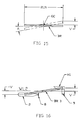
From basic trigonometry (see Fig 15 and 16), a horizontal bar BR with length 2LN, to be inclined in a longitudinal direction against the center of gravity GC with an angle A, the vertical displacements at both ends are
. When the LN is large, a small amount of inclined angle A may generate a some good amount of V. Let's apply this phenomenon to a ship by embedding a bulb (or
sub-hull 2, refer to FIG 16 and FIG 1) at one end, and widening the other end to become upper hull.
Propeller 8 and
foils 9 are adapted at suitable places. The "inclined bar" becomes a hybrid hydrofoil craft with varied characteristics. FIG 16 shows that V is the upper hull's "flying" height , and -V is the depth of the sub-hull diving. It should be noted that when the angle A approaches to zero, V and -V disappeared; implying that the draught of this craft will be much reduced when the hull (or bar) inclined toward to the other direction.
-
Therefore, the other objects of this invention are: to disclose the unique "Hull Inclination Methods" (by using said "Inclined Bar Phenomenon") for high speed ship operation; and to disclose new ship structures and means to apply said "Hull Inclination Methods", for improving operational performances.
SUMMARY OF THE INVENTION
-
Referring to FIG 16, the basic structure of water vessel of present invention consists of: an upper hull H1 placed at stern end section of said water vessel; a set of mainfoils means 9 disposed beneath said upper hull, for providing dynamic lifting force at high speed; a slender body (BR 3) placed at bow and mid sections of said water vessel for providing flotation to said water vessel.
-
For a large ship, a streamlined, generally torpedo shaped sub-hull 2 is disposed beneath the bottom portion of said slender body, for providing additional flotation to said vessel. Referring to FIG 1, let us call the slender body 3 and sub-hull 2 together as lower hull H2. When running at high speed, the center of hydrodynamic forces (L) of the mainfoils means 9, and the center of buoyancy (B) of said lower-hull H2 is offset substantially along the longitudinal axis of the vessel. The mainfoils means provide substantial rolling and pitching control, and partial lifting support. The remaining lifting is contributed by the buoyancy of said lower-hull.
-
The first embodiment of present invention is basically the combinations of a submarine and a hydrofoil craft with the mainfoils mounted at stern end.
-
The second embodiment is for a small craft using a tiltable stern drive unit. This embodiment has a slender lower-hull.
-
The third embodiment is a combination of a submarine and hydrofoil craft with the propeller means located at bow section. Two different designs are provided for bow propeller protection.
BRIEF DESCRIPTION OF THE DRAWINGS
-
All drawings provided here in this literature are somewhat schematic and wherein the like reference characters like parts in all views and drawings:
- FIG 1 through 7 are views of the first preferred embodiment.
- FIG 1 is a side elevational view of the first preferred embodiment of this invention while the vessel is at high cruising speed.
- FIG 2 is the V1-V1' section view of FIG 1.
- FIG 3 is the top view of FIG 1. This drawing shows the portion above the water line only.
- FIG 4 is the stern view of FIG 1.
- FIG 5 is the bow view of FIG 1.
- FIG 6 is a side elevational view of the vessel when the vessel is cruising at low speed.
- FIG 7 is a side elevational view of the vessel while the vessel is resting on a harbor with all foils retracted.
- FIG 8 is a side elevational view of the second embodiment, while the vessel is at high cruising speed.
- FIG 9 is the top view of FIG 8.
- FIG 10-14 are views of the third preferred embodiment.
- FIG 10 is a side elevational view of the third preferred embodiment of this invention when the vessel is at high cruising speed.
- FIG 11 is a side elevational view of the vessel when the vessel is moving backward at low speed.
- FIG 12 is a side elevational view of another alternate design of the third embodiment.
- FIG 13 is the partial bow elevational view of FIG 12.
- FIG 14 is the top elevational view of FIG 12 with the foils 10 vertically retracted.
- FIG 15 and FIG 16 are the drawings showing the "Inclined Bar Phenomenon".
DETAILED DESCRIPTIONS OF THE PREFERRED EMBODIMENTS
-
Referring to FIG 1 to FIG 7, the first preferred embodiment of this invention basically is a hydrofoil craft (upper hull H1) with a central body 1 that rides and is fixed on the stern top of a submarine (two stages hull, sub-hull 2 and 15), and said two crafts are connected by a slender body 3. On the upper hull, two stabilizers 4 and wing like wide decks 5 (in FIG 3) are disposed to both the port and starboard sides of the central body 1. A pair of retractable mainfoils 9 installed at the stern end of the central body 1. A pair of auxiliary foils 10, which are not absolutely necessary but in most cases they help for pitching and rolling control, are installed to the both sides of said sub-hull. Two main propellers 8, which generate pushing forces at high speed, are installed at the aft end of said sub-hull 2, and is located approximately at the midship of the whole system. Besides a stern rudder 25, a fore rudder 12 is adapted for improving yawing control and maneuverability.
-
A funnel 23 is adapted on the top of pilot-house 6. The sub-door 17 can be opened when docking (in FIG 7). FIG 2 shows the section view by the water line down to the sub-hull 2. It has a fish or airplane like body for minimizing water resistance. The longitudinal cross section of the slender body 3, shown with hatched lines in FIG 2, has a knife-like edges for minimizing the crucial wave resistance. FIG 3 shows the top view of the vessel above water line WL2. The wide stern section is designed for low speed stability, and the wave-piercing sharp bow visor 14 is designed for high speed capability.
-
In stern view shown in FIG 4, the mainfoils 9 have a long span for generating substantial lifting force and providing primary rolling control at high speed. Shown in FIG 5 is a bow view of FIG 1. The V bottom 19 of the central body 1 and the bottom of stabilizers 40 are designed as dynamic planes for high speed operation and for an easy takeoff. FIG 7 shown in low speed, a pair of retractable, rotatable (steerable) auxiliary propellers 20 are lowered into water for pushing ahead, pulling back or making turns.
-
One of an important and useful new feature of present invention is that: since the center of lifting forces of the mainfoils and the center of buoyancy of the lower-hull is offset substantially along the longitudinal axis of the whole vessel system, it will create moment to incline the present vessel forward or backward. This nature makes present water vessels so versatile and flexible that it can accommodate many different situations: from docking in a shallow harbor, to cruising at high speed in an open sea.
-
In FIG 1, when the vessel is cruising at high speed, the deck inclines slightly forward with an angle A3. The sub-hull 2 is buried deeply into water to improve propellent efficiency and to minimize wave making resistance. When the hydrodynamic center line of the sub-hull WLC is parallel with the water line WL2, it has the minimum water resistance. The upper hull H1 is foil borne. The forces for lifting the upper hull H1 up from the water surface are provided by: the lifting forces of the mainfoils 9, and the net buoyancy of the lower-hull.
-
Refer to FIG 1 and 6, when the speed of the vessel slows down slightly from FIG 1's condition, the lifting force L of the mainfoils 9 reduced. The stern portion of upper hull, and stabilizers 4 will be lowered and the angle of attack A2 (in FIG 6) of the mainfoils increased automatically. In turn, extra lift will be generated by the larger angle of attack A2, and compensating the reduced lifting force causing by the lost speed; therefore encouraging and keeping the upper hull H1 "flying". When the speed is slowed down further, the stern portion will finally touch down and stay on water surface as shown in FIG 6.
-
At taking off, the process is reverse. The larger angle of attack A2 of the mainfoils shown in Fig 6 creates more resistance (implying that it needs more power when taking off), but it also generates more lifting force. As speed increased, the lifting force L (shown in FIG 1) of the mainfoils increases; in turn it will raise the stern section of the upper hull H1 (including stabilizers 4) higher, and create a moment S1 times L to press the sub-hull 2 down. Then by adjusting the angle of attack of the auxiliary foils 10, or by pumping out some ballast water from the sub-hull, or doing both, a lifting force B can be created to raise up the bow section. When the vessel reaching a suitable high speed, these two forces can raise the whole upper hull H1 up and hold above the water surface; and a flying equilibrium condition can be obtained. That is:
- Horizontal forces:
- Water and air resistance forces = propellent force (not shown)
- Vertical forces :
- (shown in FIG 1)
- Moments:
- (shown in FIG 1) (In above, it is assumed that the moments created by air, water resistance and propellent forces are small and negligible.)
-
The ratio of foil lift and lower-hull buoyancy (L)/(B) can be expressed as (S2)/(S1) (shown in FIG 1). Its value depends on the application and size of a water vessel. The large vessel like the first embodiment shown in FIG 1, which may be a liquid cargo tanker, the buoyancy portion can be larger than 80%. For a small vessel such as a speed boat, the buoyancy portion can be less than 25%. For a mini-vessel such as a toy, the buoyancy portion can be less than 10%. In general, the larger the size or weight, the larger will be the buoyancy portion.
-
One of the advantages of the present embodiment is that: once the vessel reaching a constant design speed, the "flying" condition is pretty much inherently stable. If the upper hull was lowered, the angle of attack A1 (in FIG 1) automatically increased; in turn, the lifting forces of the mainfoils 9 are automatically increased to lift the upper hull up. At the front section, if the sub-hull was lowered, the increased emerged volume in the bow slender body 3 and bow central body 1 will generate extra buoyancy to lift it up, even though without the help of auxiliary foils 10. This character is more apparent for a ship having a long slender body that provides substantial buoyancy like the ship shown in FIG 8. This property makes this water vessel very easy to control the pitching movements. Therefore the principles and means of this invention can be utilized to a very small and simple water vessel such as water ski boards or toys.
-
WL3 and D3 shown in FIG 1 are the water level and the maximum draught when the present vessel is at low speed or at rest in a deep water. The D3 possibly is also the draught of the same size of current HYSWAS needed at low speed. Utilizing said "Hull Inclination Method", by inclining the hull backward longitudinally (with an angle A5 as shown in FIG 7), the vessels of present invention have a unique "draught reducing capability" not found in any type of current HYSWAS and hydrofoil crafts. When operating in a shallow water, the draught of present water vessels can be reduced by pumping out ballast water (not shown) closer to the bow end, and raising up the deepest portion of the vessel system, which is at the bottom of said sub-hull 2. The minimum draught D2 (shown in FIG 7) as at docking, is roughly 70% of the draught D1 as at high cruising speed, and is roughly 60% of the maximum draught D3 as at rest or at low speed in deep water. Therefore the operation and maintenance costs of present vessel systems will be much less than the conventional fixed hydrofoils and the current HYSWAS.
-
The present embodiment has one more advantage. That is the mainfoils 9, auxiliary foils 10, and fore rudder 12 can be retracted or raised up from the water surface to avoid hitting the sea bed when docking. These features also reduce the operation and maintenance costs.
-
The second preferred embodiment, shown in FIG 8 and FIG 9, is a smaller craft. The slender body 3 provides substantial buoyancy to said craft. The sub-hull and auxiliary fore foil are eliminated. This craft uses a tiltable stern drive unit 81 and two pairs of retractable type mainfoils 9. The propeller and mainfoils can be tilted and retracted up for beaching or launching.
-
FIG 10 through FIG 14 show the third preferred embodiment of present invention. The ship structure and the operational methods of this embodiment are similar to the first embodiment; except that the main propellent means 7 is reversible type and located at the bow end of the sub-hull and a backward steering means (including side thruster means 21) is adapted.
-
There are two advantages of mounting propellers to the bow end of a ship. First, there is no disturbing flow at the front of a ship. Second, when flying, as shown in FIG 10, the vessel is inclined slightly forward, so that the bow end is at the deepest position of entire system. By mounting propeller at this place will minimize the "cavitation" phenomena at the low pressure side of blades of a propeller, and increase the propellent efficiency thereof.
-
In order to avoid a serious damage to the fore propeller 7, the ship of this design should go backward when operating in a shallow water or harbor. A backward steering systems including a backward pilot-house 6' (shown in FIG 10 and FIG 11) is adapted. In FIG 11, by reversing the angle of attack of the propeller 7 (or turning propeller the other way), the vessel is moving backward (arrow BW showing the direction) with strut 18 retracted horizontally. The propeller 7 is well protected by moving backward. The side thruster 21 at the bow end is for making turns. The dotted lines 18' shown the strut was retracted vertically for docking. The line WLO indicates the water line for shallow water operations.
-
FIG 12 to FIG 14 illustrate another alternate design for providing fully protection to the fore propellent means. Shown in FIG 12, a fore propellent means 7 is mounted on the top structure of the sub-hull 2, and the fore end of said sub-hull is extended over the front of the propellent means 7. In this design, the machinery such as motor, power transmission or impeller means (in case of using water jet) will be embedded into the fore end section of the sub-hull 2. An extra strong structure means 31 is disposed at the end and bottom portions around the fore end of said sub-hull, for providing protection to said machinery means and fore propellent means. The auxiliary foils 10 are located by the sides of propeller 7. They can be rotated up vertically (shown in FIG 13) to protect propeller 7 being damaged by floating debris. The backward steering system is not an absolutely necessary for this design, since the flaps 36 (shown in FIG 14) can be turned to the same direction for manipulating said water vessel.
-
Furthermore, by emptying the ballast tanks close to the propeller end, said water vessel will incline, and raise the propeller 7 above the water line WLO (in FIG 12). This special feature provides a convenient access to the propellent and foil means for repairs or routine maintenance.
-
Other special features of this design are that the mainfoils 91 are the fixed and rugged type structures. The ship can be beached or launched without the delicate tilting or retracting means.
-
It should be noted that the propellers such as 8, 20 (in FIG 7, first embodiment) and 7 (in FIG 10 and FIG 12, third embodiments) can be substituted by any other types of propellent means (such as water jet, magnetohydrodynamic system or wind-sail-system etc.) whenever they are available and adaptable.