EP0800918B1 - A cylinder cleaning device and cleaning fabric receiving device - Google Patents
A cylinder cleaning device and cleaning fabric receiving device Download PDFInfo
- Publication number
- EP0800918B1 EP0800918B1 EP19970105784 EP97105784A EP0800918B1 EP 0800918 B1 EP0800918 B1 EP 0800918B1 EP 19970105784 EP19970105784 EP 19970105784 EP 97105784 A EP97105784 A EP 97105784A EP 0800918 B1 EP0800918 B1 EP 0800918B1
- Authority
- EP
- European Patent Office
- Prior art keywords
- cleaning fabric
- cleaning
- container
- roll
- fabric
- Prior art date
- Legal status (The legal status is an assumption and is not a legal conclusion. Google has not performed a legal analysis and makes no representation as to the accuracy of the status listed.)
- Expired - Lifetime
Links
Images


Classifications
-
- B—PERFORMING OPERATIONS; TRANSPORTING
- B41—PRINTING; LINING MACHINES; TYPEWRITERS; STAMPS
- B41F—PRINTING MACHINES OR PRESSES
- B41F35/00—Cleaning arrangements or devices
-
- B—PERFORMING OPERATIONS; TRANSPORTING
- B41—PRINTING; LINING MACHINES; TYPEWRITERS; STAMPS
- B41P—INDEXING SCHEME RELATING TO PRINTING, LINING MACHINES, TYPEWRITERS, AND TO STAMPS
- B41P2235/00—Cleaning
- B41P2235/10—Cleaning characterised by the methods or devices
- B41P2235/20—Wiping devices
- B41P2235/24—Wiping devices using rolls of cleaning cloth
- B41P2235/246—Pressing the cleaning cloth against the cylinder
Definitions
- the present invention relates to a cylinder cleaning device for cleaning a surface of a cylinder such as a blanket cylinder of an offset printing machine, an impression cylinder or an ink roller. More particularly, the invention relates to a cylinder cleaning device in which a cleaning fabric supply element is made in a roll form, or folded in a pleated form (or folded in zigzags), or a container holding the cleaning fabric supply element.
- a cleaning fabric as used, is wrapped around a hollow core to form a cleaning fabric roll, into which a shaft made of metal is inserted.
- This metal shaft in the cleaning unit as a rotary shaft.
- This arrangement has been widely used.
- a method of directly holding a core to make it a rotary shaft without using such metal shaft has been proposed in Japanese Patent Laid-Open No. 234659/1992 and in EP-A-0 479 403.
- An object of the present invention is to provide a cylinder cleaning device which is enabled either by thinning a roll core extremely or by using no roll core to improve the space efficiency (or space factor) of a cleaning fabric supply element and to use the cleaning fabric supply element held by a container while being small-sized.
- a cylinder cleaning device for cleaning an outer surface of a cylinder by pressing a cleaning fabric supplied from a cleaning fabric supply element against an outer surface of said cylinder, comprising: a frame; and a cleaning fabric supply element container supported on said frame; and a cleaning fabric take-up shaft attached to the frame for taking up used cleaning fabric, forming thereby a cleaning fabric take up roll, wherein the cleaning fabric take-up shaft is arranged within a range to interfere with the container when the diameter of the cleaning fabric take-up roll increases, and wherein the container includes a structure whose shape is physically changed in a direction of increasing diameter of the cleaning fabric take-up roll.
- the cleaning fabric can be easily handled, i.e., attached and detached.
- the device can be made compact by arranging the cleaning fabric take-up shaft within the range in which the cleaning fabric take-up roll interferes with the container. It is also possible to use cleaning fabric rolls or cleaning fabric supply elements of various shapes or core sizes. Moreover, the various cleaning fabric supply elements can be used merely by slightly remedying the various types of conventional cleaning device, which has already been installed.
- the cleaning fabric supply element is held in a reluctantly deformable and rigid container (e.g., a cassette or cartridge) or a deformable container a film material (including a container packaged with the film material), and the container is supported as it is, so that the handling of the cleaning fabric supply element is improved.
- a reluctantly deformable and rigid container e.g., a cassette or cartridge
- a deformable container a film material including a container packaged with the film material
- the cleaning fabric can be prevented from volatilizing or drying by the container to suppress the reduction in the performance of the cleaning fabric, so that it can be easily handled. This effect is enhanced by holding the cleaning fabric using a highly volatile detergent in the container.
- the amount of detergent to be introduced into or applied to the cleaning fabric is so high that the detergent can be prevented from leaking out of even the cleaning fabric impregnated in a saturated state and can be confined in the container.
- the cleaning fabric as supplied from the cleaning fabric supply element, can be partially drawn back to the cleaning fabric supply side and used again as a new one to improve the using efficiency of the cleaning fabric and to lower the cleaning cost and spare the resources.
- the cleaning fabric When the cleaning fabric is pressed onto the cylinder surface, a dragging force in the rotational direction of the cylinder acts upon the cleaning fabric, and this force may draw out the cleaning fabric from the cleaning fabric supply element.
- the cleaning fabric can be braked by the brake means to overcome the dragging force so that it can be prevented from being drawn out.
- cleaning fabric tensioning means moreover, there can be achieved the following advantage. If the cleaning fabric is slack, a wrinkle is formed in the cylinder pressing portion so that the cleaning fabric may not be uniformly pressed onto the cylinder surface to cause an non-homogeneous cleaning operation. With the slackness, on the other hand, the slack portion may come into contact to blot the cylinder surface or may be taken up on the cylinder, when it is not in the cleaning operation. These drawbacks can be eliminated by tensioning the cleaning fabric by the tensioning means.
- a cylinder cleaning device for cleaning the outer surface of a cylinder by pressing a cleaning fabric supplied from a cleaning fabric supply element against said outer surface of said cylinder, comprising: a frame; a receiving member attached to the frame for receiving the outer surface of the cleaning fabric supply element; a first guide member extending longitudinally of the receiving member; and a second guide member extending longitudinally of the receiving member and pairing the first guide member, wherein the first guide member and the second guide member define an S-shaped passage in-between for allowing the cleaning fabric to pass there through.
- the cleaning fabric can be stably supplied by causing it to pass through the S-shaped passage, as defined by the two guide members, from the state, in which it is received by the cleaning fabric supply element, to apply the braking action thereto and by causing it to pass through a predetermined portion near the cleaning fabric supporting receiver.
- the roll core or the diametrically reduced cleaning fabric roll is blocked, when intensively forced to come out from the cleaning fabric supporting receiver, from disengaging out by the S-shaped passage so that the roll core or the cleaning fabric roll can be accidentally wrapped by the cylinder to damage the cylinder.
- the strength of the cleaning unit can be enhanced to support the cleaning fabric supporting receiver stably and reliably.
- the braking action on the cleaning fabric can be increased by the two S-shaped passages while further enhancing the disengagement preventing effect.
- the passage of the cleaning fabric can be widely opened by turning the arm.
- the introduction of the cleaning fabric into the S-shaped passage is completed by letting off the cleaning fabric from the received cleaning fabric roll to the outside of the other guide member, by returning the turned guide member to thread the cleaning fabric into the clearance between the returned guide member and the other guide member, so that the threading work of the cleaning fabric can be facilitated.
- One guide member is turned across the open portion of the cleaning fabric supporting receiver to be charged with the cleaning fabric roll, so that it is positioned at the position opposite to the non-turned other guide member across the cleaning fabric supporting receiver.
- the cleaning fabric roll can be introduced without being hindered by the turned guide member into the cleaning fabric supporting receiver so that the charging work can be facilitated.
- the charging operation can be performed with an excellent workability by turning the cleaning fabric supporting receiver as a whole without being disengaged from the cleaning unit thereby to open the inlet side of the cleaning fabric supply element widely.
- the urging means for urging the guide member When there is provided the urging means for urging the guide member, an intense braking action can be applied to the cleaning fabric so that the cleaning fabric can be highly tensioned and reliably prevented from becoming slack.
- this cover member can be opened to introduce the cleaning fabric supply element to be charged, without disengaging the cleaning fabric supporting receiver from the cleaning unit, so that the workability can be improved.
- the cleaning fabric supply element can be introduced without disengaging the cleaning fabric supporting receiver from the cleaning unit.
- the take-up shaft is arranged in the proximity to the movable member so that the cleaning unit can be small-sized.
- the movable member When the movable member is hinged to the side of the cleaning fabric guide member, the movable member moves according to the change in the diameter of the cleaning fabric roll to move the cleaning fabric roll toward the cleaning fabric guide portion so that the direction to let off the cleaning fabric from the cleaning fabric roll is hardly changed with respect to the cleaning fabric guide portion thereby to stabilize the letting-off of the cleaning fabric.
- the disengagement preventing means for blocking the core having the wrapped cleaning fabric and the diametrically reduced cleaning fabric roll from disengaging out the safety of the cleaning work of the cylinder can be enhanced to prevent the damage of the cylinder in advance thereby to enhance the reliability of the device.
- a cleaning fabric receiving device for receiving a cleaning fabric supply element and for being mounted to a cylinder cleaning device, comprising: a mounting member including end plates and a spindle; a receiving member coupled to the mounting member for receiving the outer surface of the cleaning fabric supply element; a guide member extending longitudinally of said receiving member and define an S-shaped passage in-between for allowing the cleaning fabric to pass there through, and wherein the spindle of said mounting member is attached for use to the frame of said cylinder cleaning device.
- the present invention can be applied as an adapter without any changing work to the existing device of the type using a cleaning fabric supply element.
- the cleaning fabric supply element can have any form such as a rolled form or a folded pleated form (i.e., folded in zigzags). Cleaning fabric rolls with a round-formed roll core or a rod-formed roll core or without any roll core can also be used.
- the cleaning fabric can be made of ordinary fabric, an unwoven fabric, paper, a plastic film with or without processing, or other suitable materials. Processed cleaning fabrics include, for example, fabric previously impregnated with a detergent, fabric packaged in a vacuum pack, and fabric to which a detergent in a jellied form or a paste form has been applied.
- Fig. 1 is a sectional view showing a construction of the cylinder cleaning device of the present invention.
- Fig. 2 shows the construction showing a cleaning unit from the back side with cleaning fabric being removed.
- the cylinder cleaning device which has a container holding a cleaning fabric roll 30 as a cleaning fabric supply element 3.
- the cylinder cleaning device is constructed as a cleaning unit 2 to be mounted to face a cylinder of a press.
- This cleaning unit 2 is constructed to include: a cleaning fabric supporting receiver 4 for receiving the container holding the cleaning fabric roll 30; cleaning fabric advancing means 7 for pull-out a cleaning fabric 3a from the cleaning fabric roll 30; and a cylinder pressing part 8 for pressing the cleaning fabric 3a, as tensioned between the cleaning fabric supporting receiver 4 and the cleaning fabric advancing means 7, onto the surface of the cylinder 1.
- the cleaning fabric advancing means 7 is constructed to include a cleaning fabric take-up shaft 27 and the drive unit (not-shown) such as a motor or an air cylinder for rotating the shaft 27, so that it supplies the cleaning fabric 3a from the cleaning fabric roll 30 by taking up the used cleaning fabric on the cleaning fabric take-up shaft 27.
- a pressure pad 8a forming the cylinder pressing part 8 is supported by a supporting bar 10 which constructs a crossbeam member laid across side plates 9 arranged on both sides of the cleaning unit 2.
- the cleaning fabric supporting receiver 4 as made of a container having a rigidity, is equipped with end plates 11 which are supported by the side frames 9.
- a cover 12 which is opened to introduce the cleaning fabric roll 30 into the container.
- the cleaning fabric 3a is drawn out from a slit exit 15 which is formed between the free end of the cover 12 and the end portion of a stationary plate 14.
- the exit 15 is defined by an S wrap winding passage which is formed between the cover 12 and the stationary plate 14 by causing the end portions of the cover 12 and the stationary plate 14 to overlap each other.
- the cleaning fabric 3a is drawn out while meandering in the passage, as shown. At this time, the cleaning fabric 3a is braked and tensioned by the friction with the end portions of the two members.
- the cover 12 in order to effect the braking action, the cover 12 is urged to move toward the stationary plate 14 by a spring 16. As a result, the cover is forced to abut against the cleaning fabric 3a, as drawn out by the take-up action of the cleaning fabric advancing means 7, to increase the friction with the cleaning fabric.
- a bottom member 17 of the container is turnably attached at its one end side to the pin 13 shared with the cover 12 and is received at its other end side by a receiving bar 18 which is fixed on the side plate 9.
- the bottom member 17 may be any if it can mount the cleaning fabric supplying element 3 thereon.
- a forked member or a net member, for example, can be applied to the bottom member 17.
- a supporting unit 6 for mounting the cleaning fabric supporting receiver 4 on the side plate 9 is equipped with an irrotational shaft such as a spindle 20 having a square section at one end plate 11 (as located at the right-hand end plate in Fig. 2).
- An engaging hole 21 is formed in the other end plate 11 (as located at the left-hand end plate in Fig. 2).
- a fitting hole 22 for fitting the spindle 20 is formed in one side plate 9.
- An engaging member 23 for engaging with the engaging hole 21 is so formed in the other side plate 9 as to rotate and move toward the end plate.
- the cleaning fabric supporting receiver 4 is positioned as the ball 25 comes into the annular groove 24 of the engaging member 23.
- the annular groove 24, the ball 25 and the spring 26 of the engaging member construct a click mechanism.
- the cleaning fabric advancing means 7 is composed of the cleaning fabric take-up shaft 27 and a drive unit 28 such as a motor for rotating the shaft 27.
- the cleaning fabric 3a is supplied from the cleaning fabric roll 30 by taking up the used cleaning fabric on the cleaning fabric take-up shaft 27.
- the braking unit is disposed on the outer circumference of a rear end portion 10a of the supporting bar 10, which is extended apart from the pressure pad 8a, and at the exit 15 of the container.
- the cleaning fabric 3a as drawn out from the container, is taken up by the cleaning fabric take-up shaft 27 by bringing it around the rear end portion 10a of the supporting bar 10 into contact with the outer surface of the same and by bringing it through the supporting bar to face the pressure pad 8a at its back side.
- the cleaning fabric 3a as supplied from the cleaning fabric roll 30, is advanced in contact with the outer circumference of the rear end portion 10a of the supporting bar by the rotation of the cleaning fabric take-up shaft 27, it is tensioned by the friction with the outer surface of the rear end portion 10a. By this tension, the cleaning fabric 3a is prevented from getting slack.
- the braking action is effected by the S wrap to further enhance the cleaning fabric slackness preventing effect.
- the engaging member 23 is moved leftward from the position of Fig. 2 and is disengaged from the engaging hole 21, and the container is taken out from the cleaning unit 2.
- the cover 12 of the container is opened to introduce the cleaning fabric supplying element 3 and is closed.
- the spindle 20 of the container is fitted in the fitting hole 22 of the side plate 9, and the engaging member 23 is forced into engagement with the engaging hole 21 and is positioned by the click mechanism to set the container in the cleaning unit 2.
- the cleaning fabric, as already drawn out from the container is wrapped on the cleaning fabric take-up shaft, thus completing the preparations.
- the motor 28 is energized to supply the cleaning fabric, the cleaning fabric 3a is drawn out from the container through the S wrap of the container.
- a cleaning fabric take-up roll 70 increases.
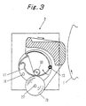
- this cleaning fabric take-up roll 70 diametrically enlarged to contact or interfere with the bottom member 17 of the container, its outer surface raises the bottom member 17, as shown in Fig. 3.
- the bottom member 17 starts its turning motion in the direction of arrow on the pin 13 so that its end portion leaves the receiving bar 18.
- the cavity space in the container is increased by the change in the remainder of the cleaning fabric supplying element 3.
- the bottom member 17 moves upward without any trouble, as shown.
- the change in the remainder of the cleaning fabric supplying element is exemplified by the reduction in the roll diameter in the case of the cleaning fabric roll 30 or by the reduction in the height in the case of the cleaning fabric in the folded pleated form.
- the cleaning fabric roll in the container, it is possible to reduce the diameter of the roll core extremely or to use the cleaning fabric supplying element having no roll core. Moreover, the size of the cleaning fabric unit can also be reduced by arranging the cleaning fabric take-up shaft close to the container.
- Fig. 4 a structure in which the bottom member is made of a deformable soft material.
- the construction other than the bottom member is identical to that of the embodiment shown in Fig. 1, and its description will be omitted by designating it by the common reference numerals.
- a deformable bottom member 29 is held at its two ends with a suitable slackness on a mounting bars 31 which are fixed on the side plate 9.
- the bottom member 29 is made of a material such as a fabric, a synthetic resin sheet or soft net.
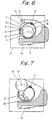
- Fig. 6 shows a structure in which the cleaning fabric supplying element is placed on an immovable bottom member.
- the present embodiment is applied to the structure in which the container is placed on the supporting bar 10, but the present invention should not be limited thereto but can be modified into a structure in which the container itself shown in Fig. 1 is held by the side plate 9.
- the container is placed on the supporting bar 10, and a movable member 40, as hinged on a pin 41, is arranged above the container.
- the movable member 40 is urged outward, as indicated by arrow, by a spring 42.
- a free end 44 of the movable member is positioned inside of the end portion 45 of a stationary bottom member 43.
- the cleaning fabric take-up shaft 27 is arranged within a range in which it is so positioned above the movable member 40 as to face and interfere with the movable member 40 as the diameter of the cleaning fabric take-up roll 70 increases.
- the couplings between the cover 12 and the bottom member 17 and between the movable member 40 and the stationary container forming member 43 are effected through the pins.
- a synthetic resin material may be used to form a hinge of a thinned portion.
- cleaning fabric pull-back means for pull-back for reuse a portion of the used cleaning fabric, which has been supplied by the cleaning fabric advancing means, to the cleaning fabric supplying element.
- the basic construction of the container itself is similar to those of the foregoing individual embodiments.
- the present embodiment can be applied to any structure for mounting the cleaning fabric supplying element, such as the structure in which the same is mounted on the movable bottom member, as shown in Fig. 1, the structure in which the same is mounted on the deformable member, as shown in Fig. 4, or the structure in which the same is mounted on the stationary container constructing member, as shown in Fig. 6.
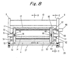
- Fig. 8 is a back elevation showing the cleaning unit with the cleaning fabric being removed.
- the container supporting receiver A is attached to the side plate (A)9.
- the container supporting receiver A is provided with a holding member (A)50 for holding one end of the container, and a spindle (A)51 disposed in the holding member (A)50.
- a spring (A)(52) for turning the holding member (A)50 in the direction (i.e., the counter-pull-out direction) opposite to the pull-out direction of the cleaning fabric.
- the spring (A)(52) is exemplified by a helical spring, as wound on the spindle (A)(51), as shown.
- first stop means for stopping the container which is turned by the pull-back rotational force stored in the spring 52, in a predetermined position.
- This first stop means is constructed by forming a projection 53 on the holding member (A)50 and a protrusion 54 at the side frame (A)9 so that it may stop the turn of the container as the projection 53 abuts against the protrusion 54.
- the holding member 50 is provided with a fitted portion 56 to be fitted in a square recess 55 formed in the end plate 11 of the container. As the fitted portion 56 is fitted in the recess 55, as shown, the holding member 50 can turn integrally with the container.
- This container supporting receiver 4 is provided with a holding member (B)60 for holding the other end of the container, and a spindle (B)61 disposed in the holding member (B)60.
- a spring (B)62 for applying a turning force to turn the holding member (B)60 in the direction (i.e., the counter-pull-out direction) opposite to the pull-out direction of the cleaning fabric.
- second stop means for stopping the container, which is turned by the pull-back rotational force stored in the spring 62, in a predetermined position.
- This second stop means is constructed by forming a projection 63 on the holding member (B)60 and a protrusion 64 at the side plate (B)9 so that it may stop the turn of the container as the projection 63 abuts against the protrusion 64.
- the position of the projection or protrusion can be made variable to adjust the pull-back motion of the container by changing that position. Thanks to this construction, the pull-back of the used cleaning fabric can be adjusted for reuse in accordance with the degree of blot of the cleaning fabric at each cleaning operation.
- the holding member 60 is provided with a fitted portion 66 to be fitted in a square recess 65 formed in the end plate 11 of the container. As the fitted portion 66 is fitted in the recess 65, as shown, the holding member 60 can turn integrally with the container.
- a retaining hole 67 is formed in such a face of the holding member 60 as to confront the side plate (B)9. The container is stopped in the position, as turned at the time of pull-out the cleaning fabric, by protruding and retaining a notch 69 in the retaining hole 67 by the retaining action of notch drive means 68.
- the cleaning fabric pull-out blocking means is disposed at each of the individual end portions of the cover 12 and the stationary plate 14, as forming the exit 15.
- a recess 73 is formed to extend in the longitudinal direction of the container.
- needle portions 74 which are so arranged at a predetermined interval in the longitudinal direction of the container as to pierce in the cleaning fabric 3a.
- the cover 12 is moved in the direction of arrow against the urging force of the spring 16 by the friction which is established by the S wrap formed between the two end portions 71 and 72, so that the needle portions 74 leave the cleaning fabric 3a being drawn out.
- the container turns in the direction of arrow of Fig. 9.
- the cover 12 is moved in the direction of arrow, as shown at (2) in Fig. 10, by the spring 16.
- the needle portions 74 pierce the cleaning fabric, as located between the two end portions, at the position of the recess 73 of the end portion 71 so that the cleaning fabric is bitten by the exit 15. If the container is turned in the arrow direction in this state, the used cleaning fabric is drawn back.
- the projection 63 is held in the position to abut against the protrusion 64 (in the state shown in Fig. 11) by the force applied in advance to the spring 62, namely, by the force to turn the container in the direction opposite to the cleaning fabric pull-out direction.
- the cleaning fabric take-up motor 28 is energized to take up the cleaning fabric 3a on the cleaning fabric take-up shaft 27.
- the container is turned in the direction (as indicated by the arrow in Fig. 12) to draw out the cleaning fabric by the friction at the instant when the cleaning fabric 3a passes through the S wrap of the container.
- the notch drive means 68 is actuated to protrude the notch 69.
- the retaining hole 67 is brought to the position of the notch 69 by the turning motion of the container, the notch 69 comes into the retaining hole 67.
- the container is held in the (A) position.
- the springs 52 and 62 store the pull-back force.
- the retention of the notch drive means 68 is released at the timing of ending the cleaning operation, the retention between the notch 69 and the retaining hole 67 is released so that the holding member 60 turns in the counter-pull-out direction together with the container, as shown in Fig. 13.
- the cleaning fabric pull-out blocking means acts to block the pull-out of the cleaning fabric from the cleaning fabric supplying element in the container. Simultaneously with this, a portion of the used cleaning fabric, e.g., about one half length of the used cleaning fabric is drawn back. At the next time of the cleaning operation, the used cleaning fabric having been drawn back is used at first so that the consumption of the cleaning fabric is reduced to utilize the resources effectively.
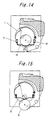
- Fig. 14 shows another embodiment of the movable bottom member.
- a bottom member 80 for mounting the cleaning fabric supplying element 3 is vertically movably supported by two guide portions 81 and 82. These guide portions 81 and 82 are mounted between the two end plates 11.
- the bottom member 80 is placed in the lowermost position of the guide portions 81 and 82 till the outer circumference of the cleaning fabric take-up roll 70 comes into abutment. When this abutment occurs, the cleaning fabric take-up roll 70 raises the bottom member 80, as shown in Fig. 15, as its diameter increases.
- Fig. 16 shows a construction of detecting the cleaning fabric end by using an optical sensor.
- This optical sensor 90 is arranged either inside of the stationary plate 14 or on the end plate 11.
- the optical sensor 90 optically detects a cleaning fabric end detecting mark on the cleaning fabric 3a, as is emanated from a hole formed in the stationary plate 14 through the exit 15.
- the detection signal is extracted from the end plate through the spindle 20 to the outside, as shown in Fig. 17, and is sent to the control unit of the not-shown cylinder cleaning device so that it is processed to monitor the end of the cleaning fabric.
- a limit switch 91 for detecting the cleaning fabric end is arranged downstream of the exit 15. This limit switch 91 is arranged either on the end plate 11 or outside of the stationary plate 14. In order to monitor the end of the cleaning fabric 3a, there is formed a hole in the vicinity of the widthwise edge of the cleaning fabric. There is processed the switch signal which is produced when the sensing lever of the limit switch 91 responds to that hole.
- the present invention may be embodied by a structure in which the same is introduced from the side end of the container.
- the cleaning fabric supplying element preferably the cleaning fabric roll is introduced into a container body 100 from its side end opening.
- the means for closing this opening is constructed of a cover member 101 having an annular portion for covering the opening from the outside, as shown at (1) in Fig. 19, or a cover member 102 having an insert to be inserted into the opening, as shown at (2) in Fig. 19.
- the outer surface of the cleaning fabric take-up roll need not act directly upon the bottom member, the movable member or the deformable member but can act upon the bottom member, the movable member or the deformable member indirectly through a mechanical association mechanism.
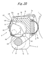
- Fig. 20 is a sectional view showing another embodiment.
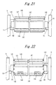
- Fig. 21 is a back elevation showing a construction of the cleaning unit with the crossbeam members being removed.
- Fig. 22 is a front elevation showing the construction of the cleaning unit with the crossbeam members being removed.
- the cleaning fabric supporting receiver 4 is equipped with semi-arcuate end members 140 which are arranged at the two sides. These end members 140 are equipped with journals 141 for supporting them on the side plates 9.
- a supporting plate 142 is fixed on the end members 140 which are positioned on the back side of the cleaning unit 2.
- a later-described cleaning fabric guide portion 143 is arranged at one end side of the supporting plate 142.
- a movable member 145 which is turnably supported by hinges 144.
- the movable member 145 of this embodiment constructs a cleaning fabric supporting receiver for receiving the outer surface of the cleaning fabric roll 30.
- a stay 146 which is mounted on the end members 140. This stay 146 receives the other end of the movable member 145 to regulate its rotation toward the cleaning fabric advancing means 7.
- the cleaning fabric take-up shaft 27 of the cleaning fabric advancing means 7 is arranged near the movable member 145. Specifically, the cleaning fabric 3a is taken up by the take-up shaft 27 of the cleaning fabric advancing means 7 so that the diameter of the cleaning fabric take-up roll 70 is increased. As a result, the outer surface of the cleaning fabric take-up roll 70 comes into interference with the movable member 145 to move the same in the direction, as indicated by broken lines. In other words, the cleaning fabric take-up roll 70 is diametrically enlarged whereas the cleaning fabric roll 30 at the side of the cleaning fabric supporting receiver is diametrically educed.
- Another method of moving the movable member may be exemplified by an indirect one in which the change in the diameter of the cleaning fabric take-up roll is detected to operate the actuating mechanism of the movable member on the basis of the detected result.
- the cleaning fabric guide portion 143 is equipped with a pair of round guide members 147 and 148. Between these guide members, there is formed an S-shaped passage for the cleaning fabric 3a to pass there through.
- the guide member 147 is arranged at the side of the cleaning fabric roll 30 whereas the guide member 148 is arranged at the side of the supporting bar 10.
- the guide member 147 is fixed at its two ends by the end members 140, and the other guide member 148 is supported at its two ends by supporting members 149 attached to the supporting plate 142.
- the supporting members 149 are made of an elastic material. The guide member, as supported by the supporting members, urges the cleaning fabric 3a passing through the S-shaped passage, in the direction to increase the friction with the other guide member.
- the supporting bar 10 has the extension 10a extending to the vicinity of the cleaning fabric guide portion 143.
- the cleaning fabric 3a is made to abut against the leading end of the extension 10a, and the guide member 148 is arranged in a position to push the cleaning fabric 3a onto the leading ends of the guide member 147 and the extension 10a of the supporting bar.
- the guide members should not be limited to the structure in which they are assembled as a portion of the cleaning fabric supporting receiver, but both or either of the guide members 147 and 148 may be mounted on the side plates 9. Likewise, the stay 146 may also be mounted on the cleaning fabric supporting receiver 4 or the side plates 9. Moreover, only one guide member 148 is urged, but the other guide member 147 may be urged in the direction opposite to that of the guide member 148 so that the cleaning fabric may be tensioned by the two guide members.
- a bearing portion 150 for receiving the journal 141 of the end member 140.
- a pair of pins 151 for mounting and positioning the journal 141 of the end member 140 at the opposite side.
- the cleaning fabric supporting receiver 4 When the cleaning fabric is to be set, the cleaning fabric supporting receiver 4 is removed from the cleaning unit 2, and the cleaning fabric roll 30 is placed on and supported by the movable member 145.
- the cleaning fabric 3a is drawn out through the S-shaped passage defined by the guide members 147 and 148, and the cleaning fabric supporting receiver 4 is then mounted on the cleaning unit 2.
- the journal of one end member 140 constructing the cleaning fabric supporting receiver 4 is inserted into the receiving portion 150 of the side plate 9, and the journal of the other end member 140 is supported on the paired pins 151 of the side plate 9. After this, the leading end of the cleaning fabric at the outside of the guide member is pulled and wrapped on the cleaning fabric take-up shaft 27 through the pressure pad 8a so that it is ready for use.
- the cleaning fabric take-up shaft 27 can be arranged in proximity of the cleaning fabric supporting receiver 4 thereby to reduce the size of the cleaning unit 2.
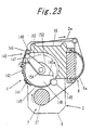
- the construction of the cleaning unit according to another embodiment is shown in Fig. 23.
- the present embodiment is characterized in the cleaning fabric guide portion in which one guide member is mounted on a turnable arm to allow the cleaning fabric to easily pass between the guide members.
- the end member 140 is equipped on its inner side with an arm mounting portion 153 which has a step 140a matching the turning range of an arm 152. From the arm mounting portion 153, there is projected an arm pin 154 for mounting the arm 152 turnably thereon.
- the guide member 147 is fixed on the leading end of the arm 152.
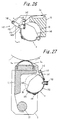
- FIG. 25 A modification of the present embodiment is shown in Fig. 25.
- the guide member 148 as arranged at the side of the supporting bar, is mounted on the arm 152.
- This arm 152 is turnably hinged to a bracket 140A which is fixed on the end member 140.
- the arm 152 is so urged by the not-shown torsion spring into the position, as indicated by the solid lines, as to form the S-shaped passage between the guide member 147 and the guide member 148.
- the cleaning fabric supporting receiver 4 When the cleaning fabric roll is to be charged, the cleaning fabric supporting receiver 4 is removed from the cleaning unit 2. After this, as shown in Fig. 24 or 26, the arm 152 is turned in a direction b, and the cleaning fabric roll 30 is placed on and received by the movable member 145. The leading portion of the cleaning fabric 3a is drawn out upward from the stationary guide member, and the arm 152 is turned in a direction a to thread the cleaning fabric into the clearance between the guide members 147 and 148. In this state, the cleaning fabric supporting receiver 4 is mounted in the cleaning unit 2 by a procedure similar to the embodiment shown in Fig. 20.
- the cleaning fabric 3a can be easily threaded through the cleaning fabric guide portion 143 so that the cleaning fabric roll 30 can be easily charged to improve the workability.
- FIG. 27 An embodiment shown in Fig. 27 is directed to a structure in which the cleaning fabric supporting receiver is fixed on the cleaning unit.
- Fig. 28 is a front elevation showing a construction of the cleaning fabric supporting receiver with the cover member being opened.
- a bottom plate 160 acting as a supporting member is attached to the end member 140 having a journal to be supported on the side plate 9.
- To the bottom plate 160 there is connected through the hinges 144 a cover member 162 for opening/closing an entrance to charge the cleaning fabric supporting receiver with the cleaning fabric roll 30.
- the cover member 162 is fastened in the closed state, as shown in Fig. 27, by a screw 163.
- the screw 163 is loosened and removed, and the cover member 162 is turned, as shown in Fig. 29, to open the entrance 161. Then, the cleaning fabric roll 30 is introduced into the entrance 161. In this operation, the leading portion of the cleaning fabric 3a is let off and placed on the guide member 147. The cleaning fabric 3a is wrapped along the pressure pad 8a on the cleaning fabric take-up shaft 27. After this, the cover member 162 is closed and fastened by the screw 163.
- the guide member 128 comes into the position, as shown in Fig. 27, to form the S-shaped passage for allowing the cleaning fabric 3a to pass there through. Simultaneously with this, the cleaning fabric 3a is tensioned by the action of the elastic force of the supporting member 149.
- the cleaning fabric roll can be charged without removing the cleaning fabric supporting receiver from the cleaning unit so that the cleaning fabric roll can be efficiently exchanged.
- An embodiment, as shown in Fig. 30, is directed to a structure in which the movable member side of the cleaning fabric supporting receiver can be widely opened at the time of charging the cleaning fabric roll.
- the cleaning fabric supporting receiver 4 is equipped with the movable member 145 and a cover member 162A.
- One side of this cover member 162A is connected to the movable member 145 by the hinge 144.
- the other side of the cover member 162A is connected to the support plate 142 through a hinge 144A.
- the cover member 162A is fixed on the end member 140 by the screw 163.
- the stay 146 With the cover member 162A being fixed, the stay 146 is arranged in the downward turning locus of the movable member 145 on the hinge 144 so that the other side of the movable member is in abutment against the stay, as shown in Fig. 30, to regulate the downward turn.
- the movable member 145 As the cleaning fabric take-up roll is diametrically enlarged, the movable member 145 is turned by the hinge of the cover member 162A which is fixed as in the embodiment of Fig. 20 by the outer circumference of the enlarged diameter of the cleaning fabric take-up roll.
- the cleaning fabric take-up roll is removed at first from the cleaning fabric take-up shaft 27, and the screw 163 is then loosened.
- the movable member 145 is turned on the hinge 144, and the cover member 162A is turned on the hinge 144A.
- the cleaning fabric roll 30 is introduced into the opening.
- the movable member 145 is introduced into the cleaning fabric supporting receiver 4 while guiding its other side at this side of the stay 146, and the cover member 162A is fixed on the end member 140 by the screw 163.
- the cleaning fabric roll 30 is charged, and the cleaning fabric guide portion 143 is threaded into the cleaning fabric guide portion 143 thereby to set the cleaning fabric roll 30 by turning the arm 152 in the arrow direction.
- the cleaning fabric supporting receiver is turnably mounted on the side plate so that it can be widely opened at the time of charging the cleaning fabric roll.
- the cleaning fabric supporting receiver 4 is so mounted as to turn on a stay 146A attached to the side plate 9.
- a stationary portion 180 is provided for holding the shown position.
- the cleaning fabric supporting receiver 4 can be turned over the arranged region of the cleaning fabric take-up shaft 27, as shown in Fig. 35, by removing the cleaning fabric take-up shaft 27.
- Reference numeral 153 designates a bearing portion which is formed in the side plate 9 and to which is connected the cleaning fabric take-up shaft 27.
- the stationary portion 180 is constructed of a click mechanism 183, as shown in Fig. 34.
- the cleaning fabric supporting receiver 4 is fixed by inserting a fixing pin 181, as projected from the side plate 9, into a hole 140b formed in the end member 140.
- a knob 182 for operating the fixing pin 181.
- In one of the annular grooves there is fitted a ball which is urged by a spring.
- the click mechanism 183 is composed of the annular grooves formed in the fixing pin 181, the ball to engage with the annular grooves, and the spring for urging the ball toward the annular grooves.
- the cleaning fabric take-up shaft is removed together with the cleaning fabric take-up roll, and the fixing portion is operated to release the cleaning fabric supporting receiver.
- the cleaning fabric supporting receiver is turned on the stay, as shown in Fig. 35, so that it is widely opened at the side of the cleaning fabric guide portion 143.
- the cleaning fabric roll is inserted into the cleaning fabric supporting receiver.
- the leading portion of the cleaning fabric is threaded through the cleaning fabric guide portion, and the cleaning fabric supporting receiver is then turned toward the supporting bar.
- the fixing portion is operated to fix the cleaning fabric supporting receiver at the position, as shown in Fig. 33.
- the cleaning fabric roll can be easily inserted by turning the cleaning fabric supporting receiver as a whole toward the cleaning fabric take-up shaft to open the cleaning fabric guide portion widely, and the cleaning unit can be small-sized by arranging the cleaning fabric take-up shaft in the proximity of the movable member.
- the cleaning fabric guide portion is constructed one guide member and a portion of the supporting bar.
- the guide member 148 is supported at its two ends on the support member 149 which is attached to the support plate 142.
- the cleaning fabric 3a advances between the guide member 148 and the end face of the extension 10a of the supporting bar.
- the supporting member 149 is made of an elastic material to push the cleaning fabric 3a onto the supporting bar 10.
- a cleaning fabric guide portion 170 for the downstream side.
- This cleaning fabric guide portion 170 is formed at the leading end of a guide plate 171 which is fixed on the supporting bar 10 or the supporting plate 9.
- the cleaning fabric 3a as located between the cleaning fabric supporting receiver 4 and the downstream cleaning fabric guide portion 170, is tensioned by pushing it onto the extension of the supporting bar by the guide member 148 of the cleaning fabric guide portion 143 thereby to establish a high friction between the guide portions.
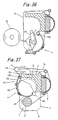
- FIG. 38 An embodiment of Fig. 38 is directed to a structure in which a disengagement preventing mechanism for preventing the cleaning fabric roll or the roll core from disengaging out is added to the cleaning unit.
- a disengagement preventing mechanism for preventing the cleaning fabric roll or the roll core from disengaging out is added to the cleaning unit.
- the guide member 148 composing the cleaning fabric guide portion 143 is given a length larger than the width of the cleaning fabric roll.
- a disengagement preventing member 172 (e.g., 172A and 172B) is disposed between the cleaning fabric guide portion 143 and the downstream cleaning fabric guide portion 170 and in the vicinity of the downstream cleaning fabric guide portion 170.
- the disengagement preventing members 172A and 172B are positioned outside of the two side portions of the cleaning fabric roll and arranged at a gap smaller than the length of the guide member 148.
- the cleaning fabric roll 30 When the cleaning fabric roll 30 is disengaged out from the cleaning fabric supporting receiver 4 by the intense pull of the cleaning fabric 3a, it comes at first into abutment against the guide member 148, as shown in Fig. 40, so that the guide member 148 moves in the direction of arrow while deforming the supporting member 149. This motion is stopped when the two ends of the guide member 148 come into abutment against the disengagement preventing members 172A and 172B. While the two ends of the guide member 148 are thus abutting against the disengagement preventing members 172A and 172B, the clearance between the guide member 148 and the lower face of the guide plate 171 of the downstream cleaning fabric guide portion 170 is narrowed to block the passage of the cleaning fabric roll 30 or a roll core 3b.
- FIG. 41 A modification of the disengagement preventing mechanism is shown in Fig. 41.
- the cleaning fabric supply element in which the roll core 3b of the cleaning fabric roll 30 is made longer than the roll width and projected from the two sides.
- the disengagement preventing mechanism is disposed close to and downstream of the guide members which form the S-shaped passage for allowing the cleaning fabric to pass there through.
- the disengagement preventing members 172A and 172B are arranged on the disengagement orbit of the roll core 3b which is protruded from the two sides of the cleaning fabric roll.
- the roll core 3b and the diametrically reduced cleaning fabric roll 30 are hooked and stopped at the two ends of the roll core 3b, when they pass and disengagement off the cleaning fabric guide portion, by the disengagement preventing members 172A and 172B, as shown in Fig. 42.
- the roll core 3b has insufficient bending strength, its central portion is deformed or bulged by the tension of the cleaning fabric.
- the roll core, as hooked by the dis-engagement preventing members may come out to disengagement out of the cleaning unit.
- the method of giving the guide members the disengagement preventing mechanism is executed by intensifying the urging force to the guide members such as by making the supporting member itself of a strong elastic material or by strengthening the spring of the arm carrying the guide members.
- the present embodiment has been described to have the construction of one guide member 148. Despite of this description, however, the present invention can naturally be applied to the construction having the two guide members 147 and 148, as represented by the cleaning fabric guide portion shown in Fig. 20.
- a cleaning fabric tensioning mechanism for preventing the cleaning fabric from becoming slack.
- the cleaning fabric tensioning mechanism may be constructed either by using one or both of the guide members as a portion of the cleaning fabric supporting receiver or by the entirety of the cleaning fabric supporting receiver.
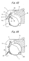
- a cleaning fabric tensioning mechanism 190 of Fig. 43 is constructed by using one guide member.
- One end 149a of the supporting member is turnably attached to the side of the cleaning fabric supporting receiver or the side plate.
- the supporting member 149 is urged in the direction of arrow by a spring 191.
- the cleaning fabric 3a is pushed and tensioned between the guide member 147 and the supporting bar 10 through the guide member 148 by the action of the spring 191.
- a cleaning fabric tensioning mechanism as shown in Fig. 44, the cleaning fabric supporting receiver 4 is turnably mounted on the stay 146A. Between the cleaning fabric supporting receiver 4 and the side plate 9, there is arranged a spring 192 for urging the cleaning fabric supporting receiver 4 in the direction of arrow. The cleaning fabric 3a is pulled and tensioned in the direction of arrow through the cleaning fabric guide portion 143.
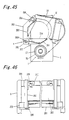
- Fig. 45 to 50 Further embodiment of the present invention is shown in Fig. 45 to 50.
- Fig. 45 is section view showing further embodiment and Fig. 46 is a front elevation showing a cleaning unit.
- a cleaning fabric passage is formed for applying brake force to the cleaning fabric by utilizing the end portion of an inner surface of the supporting bar 10 extending between the side frames 9.
- the cleaning fabric supporting receiver 4 includes a movably member 201 and a supporting plate 203 secured to arm member 202.
- the side frame are provided with shaft mounting blocks 200 on which shafts 200A are mounted.
- the movable member 201 and arm members 202 are rotatably supported on the shafts 202A.
- the movable member 201 is located in substantially horizontal position and the supporting plate 203 is located in substantially vertical position.
- the cleaning fabric roll 30 is accommodated in a space defined by the movable member 201, the supporting plate 203 and the supporting bar 10 and is placed on the movable member 201.
- the movable member 201 extends longitudinally of the cleaning fabric roll 30 and has a recess inclined toward the central portion thereof.
- End plates 204 are provided on two sides of the movable member 201 opposite to the side frames 9 to cover the lower portions of the cleaning fabric roll 30. End plates 204 limit the movement of the cleaning fabric roll 30 in longitudinal direction so that it can be held stably and reliably on the movable member 201.
- the movable member 201 is prevented from downward pivotal movement by stoppers 205 to be maintained in substantially horizontal position as shown.
- the supporting plate 203 is located in substantially vertical position opposite to the outer circumference of the cleaning fabric roll 30.
- the top end of the supporting plate 203 is positioned in the vicinity of the end portion of an inner surface of the supporting bar 10.
- a supporting plate securing mechanism is shown in which the end portions of the supporting plate 203 are secured to the side frames 9.
- This securing mechanism comprises a tubular member 206 mounted near the end portion of the supporting plate and extending over the whole length in a longitudinal direction of the supporting plate, securing member 207 projecting from both ends of the tubular member 206 toward the side frame 9 and engaging holes 208 formed in the side frames 9.
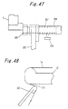
- Guide slots 210 are formed in the tubular member 206 for operating knobs 209 secured to the securing members 207 (shown in Fig. 47 with a broken line).
- Fig. 47 is a plan view of the securing mechanism provided to one of the side frames 9 and shows the securing mechanism in set condition.
- Fig. 49 shows a cleaning fabric supporting receiver in opened condition.
- the cleaning fabric roll 30 can be charged from the opening to put it on the movable member 201.
- the top end of the supporting plate 203 is arranged to position inwards from the inner end of the supporting bar 10 (about 5 mm ) as shown in Fig. 48 to form a space 211 (about 1 mm ) between these portions, through which the cleaning fabric can passes.
- the top end of the supporting plate 203 and the supporting bar 10 define an S-shaped passage and an braking force is exerted on the cleaning fabric fed through the S-shaped passage.
- the cleaning fabric take-up shaft 27 of the cleaning fabric advancing means 7 is disposed in the vicinity of the movable member 201.
- the cleaning fabric 3a is wound up by the take-up shaft 27 of the cleaning fabric advancing means 7 so that the diameter of the cleaning fabric take-up roll 70 increased.
- the outer circumference of the cleaning fabric take-up roll 70 comes into interference with the movable member 201 to move it in the direction by the arrow as shown in Fig. 50. Since this movement of the movable member 201 acts to push the diametrically reduced cleaning fabric roll 30 onto the inner face of the supporting plate 203, the cleaning fabric roll 30 is held stably and reliably in the cleaning fabric supporting receiver 4.
Description
- The present invention relates to a cylinder cleaning device for cleaning a surface of a cylinder such as a blanket cylinder of an offset printing machine, an impression cylinder or an ink roller. More particularly, the invention relates to a cylinder cleaning device in which a cleaning fabric supply element is made in a roll form, or folded in a pleated form (or folded in zigzags), or a container holding the cleaning fabric supply element.
- Conventionally, in a cylinder cleaning device for cleaning the surface of a cylinder such as a blanket cylinder of an offset printing machine, a cleaning fabric, as used, is wrapped around a hollow core to form a cleaning fabric roll, into which a shaft made of metal is inserted. This metal shaft in the cleaning unit as a rotary shaft. This arrangement has been widely used. As an improvement, a method of directly holding a core to make it a rotary shaft without using such metal shaft has been proposed in Japanese Patent Laid-Open No. 234659/1992 and in EP-A-0 479 403.
- Despite of this proposal, however, the rigidity of the cleaning fabric roll is reduced, and the center of the roll deflects by the pulling force of the cleaning fabric take-up means so that the cleaning fabric is not uniformly applied. Thus, there arises a danger that the roll is disengaged from the frame and fall into the printing machine.
- Since the external diameter of the metal shaft and the dimension of the device used for mounting a core directly on the cleaning device differ in accordance with the kind of cleaning device, not every cleaning fabric roll can be used in every kind of cleaning device. Furthermore, it is cumbersome to attach a cleaning fabric roll to the cleaning device, which involves inserting a heavy shaft of high rigidity into the core, fixing the shaft and core together, and attaching them to the cleaning unit.
- There has also been proposed a cleaning fabric roll which is made efficient and economical by reducing the portion of the core, i.e., the roll core extremely to wrap the cleaning fabric more. Since a diametrically reduced core has to be used, however, there is raised a problem in strength by the conventional mounting method, and this problem has been desired to be solved.
- For this solution, we have proposed in Japanese Patent Application No. 352877/1995 a cylinder cleaning device having a structure, in which the outer surface of a cleaning fabric supply element is mounted on the inner wall of a container. According to this structure, the distance between the container and the cleaning fabric take-up roll is so enlarged in advance that the outer surface of the cleaning fabric take-up roll may not abut against the container even if the cleaning operation advances to enlarge the diameter of the cleaning fabric take-up roll. As a result, if the container holding the cleaning fabric supply element is enabled to be used, there arises a problem that the device is more large-sized than the type using only the cleaning fabric supply element.
- An object of the present invention is to provide a cylinder cleaning device which is enabled either by thinning a roll core extremely or by using no roll core to improve the space efficiency (or space factor) of a cleaning fabric supply element and to use the cleaning fabric supply element held by a container while being small-sized.
- According to the present invention, there is provided a cylinder cleaning device for cleaning an outer surface of a cylinder by pressing a cleaning fabric supplied from a cleaning fabric supply element against an outer surface of said cylinder, comprising: a frame; and a cleaning fabric supply element container supported on said frame; and a cleaning fabric take-up shaft attached to the frame for taking up used cleaning fabric, forming thereby a cleaning fabric take up roll, wherein the cleaning fabric take-up shaft is arranged within a range to interfere with the container when the diameter of the cleaning fabric take-up roll increases, and wherein the container includes a structure whose shape is physically changed in a direction of increasing diameter of the cleaning fabric take-up roll.
- Thanks to the aforementioned structure in which the outer surface of the cleaning fabric supply element is received, it is possible to remarkably easily charge many kinds of rolls of different kinds such as cleaning fabric roll having different cores or cleaning fabric rolls having no core without using any metal shaft.
- Especially thanks to the structure in which the cleaning fabric is held in the container, the cleaning fabric can be easily handled, i.e., attached and detached. At the same time, the device can be made compact by arranging the cleaning fabric take-up shaft within the range in which the cleaning fabric take-up roll interferes with the container. It is also possible to use cleaning fabric rolls or cleaning fabric supply elements of various shapes or core sizes. Moreover, the various cleaning fabric supply elements can be used merely by slightly remedying the various types of conventional cleaning device, which has already been installed.
- In a preferable mode, the cleaning fabric supply element is held in a reluctantly deformable and rigid container (e.g., a cassette or cartridge) or a deformable container a film material (including a container packaged with the film material), and the container is supported as it is, so that the handling of the cleaning fabric supply element is improved. Especially in the case of the cleaning fabric which is impregnated with a liquid, jellied or pasty detergent or to which the detergent is applied, the cleaning fabric can be prevented from volatilizing or drying by the container to suppress the reduction in the performance of the cleaning fabric, so that it can be easily handled. This effect is enhanced by holding the cleaning fabric using a highly volatile detergent in the container. When much detergent is used as in the cleaning fabric employed in a cylinder cleaning device of an offset printing machine, for example, the amount of detergent to be introduced into or applied to the cleaning fabric is so high that the detergent can be prevented from leaking out of even the cleaning fabric impregnated in a saturated state and can be confined in the container.
- Especially thanks to the provision of cleaning fabric pull-back means, the cleaning fabric, as supplied from the cleaning fabric supply element, can be partially drawn back to the cleaning fabric supply side and used again as a new one to improve the using efficiency of the cleaning fabric and to lower the cleaning cost and spare the resources.
- Thanks to the provision of brake means, moreover, the following advantage can be achieved. When the cleaning fabric is pressed onto the cylinder surface, a dragging force in the rotational direction of the cylinder acts upon the cleaning fabric, and this force may draw out the cleaning fabric from the cleaning fabric supply element. However, the cleaning fabric can be braked by the brake means to overcome the dragging force so that it can be prevented from being drawn out.
- Thanks to the provision of cleaning fabric tensioning means, moreover, there can be achieved the following advantage. If the cleaning fabric is slack, a wrinkle is formed in the cylinder pressing portion so that the cleaning fabric may not be uniformly pressed onto the cylinder surface to cause an non-homogeneous cleaning operation. With the slackness, on the other hand, the slack portion may come into contact to blot the cylinder surface or may be taken up on the cylinder, when it is not in the cleaning operation. These drawbacks can be eliminated by tensioning the cleaning fabric by the tensioning means.
- On the other hand, there is provided a cylinder cleaning device for cleaning the outer surface of a cylinder by pressing a cleaning fabric supplied from a cleaning fabric supply element against said outer surface of said cylinder, comprising: a frame; a receiving member attached to the frame for receiving the outer surface of the cleaning fabric supply element; a first guide member extending longitudinally of the receiving member; and a second guide member extending longitudinally of the receiving member and pairing the first guide member, wherein the first guide member and the second guide member define an S-shaped passage in-between for allowing the cleaning fabric to pass there through.
- In the case of the aforementioned construction, the cleaning fabric can be stably supplied by causing it to pass through the S-shaped passage, as defined by the two guide members, from the state, in which it is received by the cleaning fabric supply element, to apply the braking action thereto and by causing it to pass through a predetermined portion near the cleaning fabric supporting receiver.
- Moreover, the roll core or the diametrically reduced cleaning fabric roll is blocked, when intensively forced to come out from the cleaning fabric supporting receiver, from disengaging out by the S-shaped passage so that the roll core or the cleaning fabric roll can be accidentally wrapped by the cylinder to damage the cylinder.
- Especially by providing the crossbeam member, the strength of the cleaning unit can be enhanced to support the cleaning fabric supporting receiver stably and reliably.
- By using one guide member to form the S-shaped passage between it and the crossbeam member, moreover, the braking action on the cleaning fabric can be increased by the two S-shaped passages while further enhancing the disengagement preventing effect.
- When one guide member is attached to the turnable arm, the passage of the cleaning fabric can be widely opened by turning the arm. As a result, the introduction of the cleaning fabric into the S-shaped passage is completed by letting off the cleaning fabric from the received cleaning fabric roll to the outside of the other guide member, by returning the turned guide member to thread the cleaning fabric into the clearance between the returned guide member and the other guide member, so that the threading work of the cleaning fabric can be facilitated.
- One guide member is turned across the open portion of the cleaning fabric supporting receiver to be charged with the cleaning fabric roll, so that it is positioned at the position opposite to the non-turned other guide member across the cleaning fabric supporting receiver. As a result, the cleaning fabric roll can be introduced without being hindered by the turned guide member into the cleaning fabric supporting receiver so that the charging work can be facilitated.
- When one side of the cleaning fabric supporting receiver is turnably attached to the frame, the charging operation can be performed with an excellent workability by turning the cleaning fabric supporting receiver as a whole without being disengaged from the cleaning unit thereby to open the inlet side of the cleaning fabric supply element widely.
- When there is provided the urging means for urging the guide member, an intense braking action can be applied to the cleaning fabric so that the cleaning fabric can be highly tensioned and reliably prevented from becoming slack.
- When the cleaning fabric supporting receiver is partially made of the cover member, this cover member can be opened to introduce the cleaning fabric supply element to be charged, without disengaging the cleaning fabric supporting receiver from the cleaning unit, so that the workability can be improved.
- With the construction in which the movable member and the cover member make up the receiving member of the cleaning fabric supply element so that the cleaning fabric supply element is introduced into the portion to be opened by turning those members, the cleaning fabric supply element can be introduced without disengaging the cleaning fabric supporting receiver from the cleaning unit. At the same time, the take-up shaft is arranged in the proximity to the movable member so that the cleaning unit can be small-sized.
- When the movable member is hinged to the side of the cleaning fabric guide member, the movable member moves according to the change in the diameter of the cleaning fabric roll to move the cleaning fabric roll toward the cleaning fabric guide portion so that the direction to let off the cleaning fabric from the cleaning fabric roll is hardly changed with respect to the cleaning fabric guide portion thereby to stabilize the letting-off of the cleaning fabric.
- Since there is provided the disengagement preventing means for blocking the core having the wrapped cleaning fabric and the diametrically reduced cleaning fabric roll from disengaging out, the safety of the cleaning work of the cylinder can be enhanced to prevent the damage of the cylinder in advance thereby to enhance the reliability of the device.
- On the other hand, there is provided a cleaning fabric receiving device for receiving a cleaning fabric supply element and for being mounted to a cylinder cleaning device, comprising: a mounting member including end plates and a spindle; a receiving member coupled to the mounting member for receiving the outer surface of the cleaning fabric supply element; a guide member extending longitudinally of said receiving member and define an S-shaped passage in-between for allowing the cleaning fabric to pass there through, and wherein the spindle of said mounting member is attached for use to the frame of said cylinder cleaning device.
- With the aforementioned construction, the present invention can be applied as an adapter without any changing work to the existing device of the type using a cleaning fabric supply element.
-
- Fig. 1 is a sectional view showing the basic arrangement of a cylinder cleaning device of the present invention;
- Fig. 2 is a back elevation showing a cleaning unit from which is removed a cleaning fabric;
- Fig. 3 is an explanatory view showing a relation between a cleaning fabric take-up roll and a bottom member;
- Fig. 4 is a sectional view showing a structure in which the bottom member is made of a deformable soft material;
- Fig. 5 is an explanatory view showing a relation between the cleaning fabric take-up roll and the soft bottom member;
- Fig. 6 is a sectional view showing a structure in which a cleaning fabric supply element is mounted on an immovable bottom member;
- Fig. 7 is a diagram for explaining a relation between the cleaning fabric take-up roll and a movable member;
- Fig. 8 is a back elevation showing the basic arrangement of a cylinder cleaning device having a mechanism for pull-back a portion of the used cleaning fabric with the cleaning fabric being removed;
- Fig. 9 is a sectional view taken along line B - B of Fig. 8;
- Fig. 10 are explanatory diagrams showing a specific example of cleaning fabric extraction blocking means in the cleaning fabric extracting state at (1) and in the cleaning fabric pull-back state at (2);
- Fig. 11 is a view showing the state before the start of the cleaning operation and taken along line C - C of Fig. 8;
- Fig. 12 is a view showing the state at the cleaning fabric extracting time and taken along line C - C of Fig. 8;
- Fig. 13 is a view showing the state at the cleaning fabric pull-back time and taken along line C - C of Fig. 8;
- Fig. 14 is a sectional view showing another embodiment of the movable bottom member;
- Fig. 15 is an explanatory view showing a relation between the cleaning fabric take-up roll and the bottom member;
- Fig. 16 is a sectional view showing an embodiment of the detection of a cleaning fabric end;
- Fig. 17 is a back elevation of Fig. 16;
- Fig. 18 is a sectional view showing another embodiment of the detection of a cleaning fabric end;
- Fig. 19 is an explanatory view showing a structure for inserting the cleaning fabric supply element from the side end of a container;
- Fig. 20 is a sectional view showing another embodiment;
- Fig. 21 is a back elevation showing a cleaning unit from which is removed the cleaning fabric;
- Fig. 22 is a front elevation showing the cleaning unit from which is removed the cleaning fabric;
- Fig. 23 is a sectional view showing another embodiment;
- Fig. 24 is an explanatory view showing the case of charging a cleaning fabric roll;
- Fig. 25 is a sectional view showing a modification of a cleaning fabric guide portion;
- Fig. 26 is an explanatory view showing the action of Fig. 25;
- Fig. 27 is a sectional view showing another embodiment;
- Fig. 28 is a front elevation showing a cleaning fabric receiving portion;
- Fig. 29 is an explanatory view showing the case of charging the cleaning fabric roll;
- Fig. 30 is a sectional view showing another embodiment;
- Fig. 31 is an explanatory view showing the case of charging the cleaning fabric roll;
- Fig. 32 is a sectional view showing a modification of the cleaning fabric guide portion;
- Fig. 33 is a sectional view showing another embodiment;
- Fig. 34 is an enlarged sectional view showing a fixing portion;
- Fig. 35 is an explanatory view showing the case of charging the cleaning fabric roll;
- Fig. 36 is a sectional view showing a modification of the cleaning fabric guide portion;
- Fig. 37 is a sectional view showing another embodiment;
- Fig. 38 is a sectional view showing another embodiment;
- Fig. 39 is a front elevation of Fig. 38;
- Fig. 40 is an explanatory view showing a disengagement preventing mechanism;
- Fig. 41 is a front elevation showing a modification of a disengagement preventing mechanism;
- Fig. 42 is an explanatory view showing the disengagement preventing mechanism;
- Fig. 43 is a sectional view showing another embodiment;
- Fig. 44 is a sectional view showing a modification of a cleaning fabric tensioning mechanism.
- Fig. 45 is a sectional view showing further embodiment;
- Fig. 46 is a front elevation showing the cleaning unit from which is removed the cleaning fabric;
- Fig. 47 is a plan view showing a supporting plate securing mechanism;
- Fig. 48 is a view for explaining an arrangement of the top of the supporting plate and the supporting bar;
- Fig. 49 is a view for explaining the case of charging the cleaning fabric roll; and
- Fig. 50 is a view for explaining an arrangement of the movable member and the cleaning fabric take-up shaft.
-
- A common characteristic of the present invention is that the cleaning fabric supply element can have any form such as a rolled form or a folded pleated form (i.e., folded in zigzags). Cleaning fabric rolls with a round-formed roll core or a rod-formed roll core or without any roll core can also be used. The cleaning fabric can be made of ordinary fabric, an unwoven fabric, paper, a plastic film with or without processing, or other suitable materials. Processed cleaning fabrics include, for example, fabric previously impregnated with a detergent, fabric packaged in a vacuum pack, and fabric to which a detergent in a jellied form or a paste form has been applied.
- Fig. 1 is a sectional view showing a construction of the cylinder cleaning device of the present invention. Fig. 2 shows the construction showing a cleaning unit from the back side with cleaning fabric being removed. In the present embodiment, here will be described the cylinder cleaning device which has a container holding a cleaning
fabric roll 30 as a cleaningfabric supply element 3. The cylinder cleaning device is constructed as acleaning unit 2 to be mounted to face a cylinder of a press. Thiscleaning unit 2 is constructed to include: a cleaningfabric supporting receiver 4 for receiving the container holding the cleaningfabric roll 30; cleaningfabric advancing means 7 for pull-out a cleaningfabric 3a from the cleaningfabric roll 30; and a cylinderpressing part 8 for pressing the cleaningfabric 3a, as tensioned between the cleaningfabric supporting receiver 4 and the cleaningfabric advancing means 7, onto the surface of thecylinder 1. - The cleaning
fabric advancing means 7 is constructed to include a cleaning fabric take-upshaft 27 and the drive unit (not-shown) such as a motor or an air cylinder for rotating theshaft 27, so that it supplies the cleaningfabric 3a from the cleaningfabric roll 30 by taking up the used cleaning fabric on the cleaning fabric take-upshaft 27. Apressure pad 8a forming the cylinderpressing part 8 is supported by a supportingbar 10 which constructs a crossbeam member laid acrossside plates 9 arranged on both sides of thecleaning unit 2. - Here will be described concrete examples of each of the above-described parts. The cleaning
fabric supporting receiver 4, as made of a container having a rigidity, is equipped withend plates 11 which are supported by the side frames 9. At the charging entrance of the cleaningfabric supplying element 3 of the container, there is hinged on a pin 13 acover 12 which is opened to introduce the cleaningfabric roll 30 into the container. The cleaningfabric 3a is drawn out from aslit exit 15 which is formed between the free end of thecover 12 and the end portion of astationary plate 14. Theexit 15 is defined by an S wrap winding passage which is formed between thecover 12 and thestationary plate 14 by causing the end portions of thecover 12 and thestationary plate 14 to overlap each other. The cleaningfabric 3a is drawn out while meandering in the passage, as shown. At this time, the cleaningfabric 3a is braked and tensioned by the friction with the end portions of the two members. - In the present embodiment, in order to effect the braking action, the
cover 12 is urged to move toward thestationary plate 14 by aspring 16. As a result, the cover is forced to abut against the cleaningfabric 3a, as drawn out by the take-up action of the cleaningfabric advancing means 7, to increase the friction with the cleaning fabric. - A
bottom member 17 of the container is turnably attached at its one end side to thepin 13 shared with thecover 12 and is received at its other end side by a receivingbar 18 which is fixed on theside plate 9. Thebottom member 17 may be any if it can mount the cleaningfabric supplying element 3 thereon. A forked member or a net member, for example, can be applied to thebottom member 17. - A supporting
unit 6 for mounting the cleaningfabric supporting receiver 4 on theside plate 9 is equipped with an irrotational shaft such as aspindle 20 having a square section at one end plate 11 (as located at the right-hand end plate in Fig. 2). An engaginghole 21 is formed in the other end plate 11 (as located at the left-hand end plate in Fig. 2). Afitting hole 22 for fitting thespindle 20 is formed in oneside plate 9. An engagingmember 23 for engaging with the engaginghole 21 is so formed in theother side plate 9 as to rotate and move toward the end plate. In the engagingmember 23, there is formed anannular groove 24 for positions to engage with the engaginghole 21 and not. In theside plate 9, there are arranged aball 25 and aspring 26 for pushing the balls. The cleaningfabric supporting receiver 4 is positioned as theball 25 comes into theannular groove 24 of the engagingmember 23. Here, theannular groove 24, theball 25 and thespring 26 of the engaging member construct a click mechanism. - The cleaning
fabric advancing means 7 is composed of the cleaning fabric take-upshaft 27 and adrive unit 28 such as a motor for rotating theshaft 27. The cleaningfabric 3a is supplied from the cleaningfabric roll 30 by taking up the used cleaning fabric on the cleaning fabric take-upshaft 27. - In Fig. 1, the braking unit is disposed on the outer circumference of a
rear end portion 10a of the supportingbar 10, which is extended apart from thepressure pad 8a, and at theexit 15 of the container. The cleaningfabric 3a, as drawn out from the container, is taken up by the cleaning fabric take-upshaft 27 by bringing it around therear end portion 10a of the supportingbar 10 into contact with the outer surface of the same and by bringing it through the supporting bar to face thepressure pad 8a at its back side. When the cleaningfabric 3a, as supplied from the cleaningfabric roll 30, is advanced in contact with the outer circumference of therear end portion 10a of the supporting bar by the rotation of the cleaning fabric take-upshaft 27, it is tensioned by the friction with the outer surface of therear end portion 10a. By this tension, the cleaningfabric 3a is prevented from getting slack. At theexit 15 at the container side, too, the braking action is effected by the S wrap to further enhance the cleaning fabric slackness preventing effect. - The actions of the above-described embodiment will now be described. The engaging
member 23 is moved leftward from the position of Fig. 2 and is disengaged from the engaginghole 21, and the container is taken out from thecleaning unit 2. Thecover 12 of the container is opened to introduce the cleaningfabric supplying element 3 and is closed. Thespindle 20 of the container is fitted in thefitting hole 22 of theside plate 9, and the engagingmember 23 is forced into engagement with the engaginghole 21 and is positioned by the click mechanism to set the container in thecleaning unit 2. The cleaning fabric, as already drawn out from the container, is wrapped on the cleaning fabric take-up shaft, thus completing the preparations. When themotor 28 is energized to supply the cleaning fabric, the cleaningfabric 3a is drawn out from the container through the S wrap of the container. - As the used cleaning fabric is taken up on the cleaning fabric take-up
shaft 27, the diameter of a cleaning fabric take-up roll 70 increases. When this cleaning fabric take-up roll 70 diametrically enlarged to contact or interfere with thebottom member 17 of the container, its outer surface raises thebottom member 17, as shown in Fig. 3. In other words, thebottom member 17 starts its turning motion in the direction of arrow on thepin 13 so that its end portion leaves the receivingbar 18. In this motion, the cavity space in the container is increased by the change in the remainder of the cleaningfabric supplying element 3. As a result, thebottom member 17 moves upward without any trouble, as shown. The change in the remainder of the cleaning fabric supplying element is exemplified by the reduction in the roll diameter in the case of the cleaningfabric roll 30 or by the reduction in the height in the case of the cleaning fabric in the folded pleated form. - By thus using the cleaning fabric roll in the container, it is possible to reduce the diameter of the roll core extremely or to use the cleaning fabric supplying element having no roll core. Moreover, the size of the cleaning fabric unit can also be reduced by arranging the cleaning fabric take-up shaft close to the container.
- As another embodiment of the present invention, there is shown in Fig. 4 a structure in which the bottom member is made of a deformable soft material. Incidentally, the construction other than the bottom member is identical to that of the embodiment shown in Fig. 1, and its description will be omitted by designating it by the common reference numerals. A
deformable bottom member 29 is held at its two ends with a suitable slackness on a mounting bars 31 which are fixed on theside plate 9. Thebottom member 29 is made of a material such as a fabric, a synthetic resin sheet or soft net. When the cleaningfabric roll 30 is inserted into the container, it is stably placed by the hammock, as shown. - As the used cleaning
fabric 3a is taken up on the cleaning fabric take-upshaft 27 to increase the diameter of the cleaning fabric take-up roll 70, this take-up roll 70 comes into the state to interfere with thebottom member 29. The outer surface of the cleaning fabric take-up roll 70 raises thebottom member 29, as shown in Fig. 5. At this time, thebottom member 29 is so deformed along the outer circumference of the cleaning fabric take-up roll 70 as to bulge into the container. The cleaningfabric roll 30 moves into either the right-hand or left-hand trough until it is stably held according to the change in the diameter. - Fig. 6 shows a structure in which the cleaning fabric supplying element is placed on an immovable bottom member. The present embodiment is applied to the structure in which the container is placed on the supporting
bar 10, but the present invention should not be limited thereto but can be modified into a structure in which the container itself shown in Fig. 1 is held by theside plate 9. In Fig. 6, the container is placed on the supportingbar 10, and amovable member 40, as hinged on apin 41, is arranged above the container. Themovable member 40 is urged outward, as indicated by arrow, by aspring 42. Afree end 44 of the movable member is positioned inside of theend portion 45 of astationary bottom member 43. As a result, as the cleaningfabric 3a passes between the end portions, the elastic force of thespring 42 acts upon the S wrap to establish the braking action thereby to prevent the cleaning fabric from getting slack. The cleaning fabric take-upshaft 27 is arranged within a range in which it is so positioned above themovable member 40 as to face and interfere with themovable member 40 as the diameter of the cleaning fabric take-up roll 70 increases. - When the used cleaning fabric is taken up to increase the diameter of the cleaning fabric take-
up roll 70, this take-up roll 70 comes into the state to interfere with themovable member 40. As shown in Fig. 7, themovable member 40 is pushed down by the outer surface of the cleaning fabric take-up roll 70. In short, themovable member 40 starts to turn in the direction of arrow on thepin 41. In this motion, a large cavity space is left in the container by the change in the remainder of the cleaning fabric supplying element. As a result, themovable member 40 can turn downward without any trouble, as shown. - In the present embodiment, the couplings between the
cover 12 and thebottom member 17 and between themovable member 40 and the stationarycontainer forming member 43 are effected through the pins. In a construction other than the pins, for example, a synthetic resin material may be used to form a hinge of a thinned portion. - Here will be described a specific example of cleaning fabric pull-back means for pull-back for reuse a portion of the used cleaning fabric, which has been supplied by the cleaning fabric advancing means, to the cleaning fabric supplying element.
Incidentally, the basic construction of the container itself is similar to those of the foregoing individual embodiments. The present embodiment can be applied to any structure for mounting the cleaning fabric supplying element, such as the structure in which the same is mounted on the movable bottom member, as shown in Fig. 1, the structure in which the same is mounted on the deformable member, as shown in Fig. 4, or the structure in which the same is mounted on the stationary container constructing member, as shown in Fig. 6. - Fig. 8 is a back elevation showing the cleaning unit with the cleaning fabric being removed. For explanatory purposes, the parts, as located at the left-hand side of Fig. 8, are designated by "A", whereas the parts at the right-hand side are designated by "B". A container supporting receiver A is attached to the side plate (A)9. The container supporting receiver A is provided with a holding member (A)50 for holding one end of the container, and a spindle (A)51 disposed in the holding member (A)50. Further provided is a spring (A)(52) for turning the holding member (A)50 in the direction (i.e., the counter-pull-out direction) opposite to the pull-out direction of the cleaning fabric. In this embodiment, the spring (A)(52) is exemplified by a helical spring, as wound on the spindle (A)(51), as shown. Further provided first stop means for stopping the container, which is turned by the pull-back rotational force stored in the
spring 52, in a predetermined position. This first stop means is constructed by forming aprojection 53 on the holding member (A)50 and aprotrusion 54 at the side frame (A)9 so that it may stop the turn of the container as theprojection 53 abuts against theprotrusion 54. The holdingmember 50 is provided with a fittedportion 56 to be fitted in asquare recess 55 formed in theend plate 11 of the container. As the fittedportion 56 is fitted in therecess 55, as shown, the holdingmember 50 can turn integrally with the container. - To the side plate (B) 9, there is attached the
container supporting receiver 4. Thiscontainer supporting receiver 4 is provided with a holding member (B)60 for holding the other end of the container, and a spindle (B)61 disposed in the holding member (B)60. There is provided a spring (B)62 for applying a turning force to turn the holding member (B)60 in the direction (i.e., the counter-pull-out direction) opposite to the pull-out direction of the cleaning fabric. Further provided second stop means for stopping the container, which is turned by the pull-back rotational force stored in thespring 62, in a predetermined position. This second stop means is constructed by forming aprojection 63 on the holding member (B)60 and aprotrusion 64 at the side plate (B)9 so that it may stop the turn of the container as theprojection 63 abuts against theprotrusion 64. For the turning stop of the container, the position of the projection or protrusion can be made variable to adjust the pull-back motion of the container by changing that position. Thanks to this construction, the pull-back of the used cleaning fabric can be adjusted for reuse in accordance with the degree of blot of the cleaning fabric at each cleaning operation. - The holding
member 60 is provided with a fittedportion 66 to be fitted in asquare recess 65 formed in theend plate 11 of the container. As the fittedportion 66 is fitted in therecess 65, as shown, the holdingmember 60 can turn integrally with the container. A retaininghole 67 is formed in such a face of the holdingmember 60 as to confront the side plate (B)9. The container is stopped in the position, as turned at the time of pull-out the cleaning fabric, by protruding and retaining anotch 69 in the retaininghole 67 by the retaining action of notch drive means 68. - If the friction to be established between the container and the cleaning fabric take-up shaft by a supporting bar or pressure pad is higher than that at the S wrap portion of the
container exit 15 when a portion of the used cleaning fabric is drawn back, it is drawn out from the inside of the container when the container is turned in the direction, as shown in Fig. 9. In other words, the portion of the used cleaning fabric cannot be drawn back. As a counter-measure for this drawback, there is disposed cleaning fabric pull-out blocking means at the container side. This cleaning fabric pull-out blocking means can be operated at the time of pull-back the used cleaning fabric, to block the pull-out of the cleaning fabric from the container. - In the embodiment shown in Fig. 9, the cleaning fabric pull-out blocking means is disposed at each of the individual end portions of the
cover 12 and thestationary plate 14, as forming theexit 15. At theend portion 71 of thecover 12, as shown in Fig. 10, arecess 73 is formed to extend in the longitudinal direction of the container. At theend portion 72 of thestationary plate 14, there are formedneedle portions 74 which are so arranged at a predetermined interval in the longitudinal direction of the container as to pierce in the cleaningfabric 3a. Here will be described the relation between therecess 73 and theneedle portions 74. At the time of pull-out the cleaning fabric, as shown at (1) in Fig. 10, thecover 12 is moved in the direction of arrow against the urging force of thespring 16 by the friction which is established by the S wrap formed between the twoend portions needle portions 74 leave the cleaningfabric 3a being drawn out. In the pull-back action of the used cleaning fabric, the container turns in the direction of arrow of Fig. 9. As a result, there disappears the friction to be established by the S wrap between the end portions and the used cleaning fabric. As a result, thecover 12 is moved in the direction of arrow, as shown at (2) in Fig. 10, by thespring 16. When theend portion 71 of thecover 12 abuts against theend portion 72 of thestationary plate 14, theneedle portions 74 pierce the cleaning fabric, as located between the two end portions, at the position of therecess 73 of theend portion 71 so that the cleaning fabric is bitten by theexit 15. If the container is turned in the arrow direction in this state, the used cleaning fabric is drawn back. - In the above-described embodiment, when the notch drive means 68 is released to release the
notch 69 and the retaininghole 67, theprojection 63 is held in the position to abut against the protrusion 64 (in the state shown in Fig. 11) by the force applied in advance to thespring 62, namely, by the force to turn the container in the direction opposite to the cleaning fabric pull-out direction. At the time of pull-out the cleaning fabric, the cleaning fabric take-upmotor 28 is energized to take up the cleaningfabric 3a on the cleaning fabric take-upshaft 27. At this time, the container is turned in the direction (as indicated by the arrow in Fig. 12) to draw out the cleaning fabric by the friction at the instant when the cleaningfabric 3a passes through the S wrap of the container. As timed with this, the notch drive means 68 is actuated to protrude thenotch 69. When the retaininghole 67 is brought to the position of thenotch 69 by the turning motion of the container, thenotch 69 comes into the retaininghole 67. The container is held in the (A) position. In this motion, thesprings notch 69 and the retaininghole 67 is released so that the holdingmember 60 turns in the counter-pull-out direction together with the container, as shown in Fig. 13. As a result of the turning motion of the container, the cleaning fabric pull-out blocking means, as arranged at theexit 15, acts to block the pull-out of the cleaning fabric from the cleaning fabric supplying element in the container. Simultaneously with this, a portion of the used cleaning fabric, e.g., about one half length of the used cleaning fabric is drawn back. At the next time of the cleaning operation, the used cleaning fabric having been drawn back is used at first so that the consumption of the cleaning fabric is reduced to utilize the resources effectively. - Fig. 14 shows another embodiment of the movable bottom member. In the present embodiment, a
bottom member 80 for mounting the cleaningfabric supplying element 3 is vertically movably supported by twoguide portions portions end plates 11. Thebottom member 80 is placed in the lowermost position of theguide portions up roll 70 comes into abutment. When this abutment occurs, the cleaning fabric take-up roll 70 raises thebottom member 80, as shown in Fig. 15, as its diameter increases. - Fig. 16 shows a construction of detecting the cleaning fabric end by using an optical sensor. This
optical sensor 90 is arranged either inside of thestationary plate 14 or on theend plate 11. Theoptical sensor 90 optically detects a cleaning fabric end detecting mark on the cleaningfabric 3a, as is emanated from a hole formed in thestationary plate 14 through theexit 15. The detection signal is extracted from the end plate through thespindle 20 to the outside, as shown in Fig. 17, and is sent to the control unit of the not-shown cylinder cleaning device so that it is processed to monitor the end of the cleaning fabric. - The construction of another embodiment for detecting the cleaning fabric end is shown in Fig. 18. In this construction, a
limit switch 91 for detecting the cleaning fabric end is arranged downstream of theexit 15. Thislimit switch 91 is arranged either on theend plate 11 or outside of thestationary plate 14. In order to monitor the end of the cleaningfabric 3a, there is formed a hole in the vicinity of the widthwise edge of the cleaning fabric. There is processed the switch signal which is produced when the sensing lever of thelimit switch 91 responds to that hole. - The aforementioned embodiment has been described in connection with the structure in which the cleaning fabric supplying element is set in the container from a charging entrance formed in the outer circumferential portion, but the present invention may be embodied by a structure in which the same is introduced from the side end of the container. In this modification, there can be suitably selected the structure, in which the end plate can be freely removed, or the structure in which the charging entrance is formed in the stationary end plate so that a cap can be freely removed from the charging entrance. In the embodiment shown in Fig. 19, the cleaning fabric supplying element, preferably the cleaning fabric roll is introduced into a
container body 100 from its side end opening. The means for closing this opening is constructed of acover member 101 having an annular portion for covering the opening from the outside, as shown at (1) in Fig. 19, or acover member 102 having an insert to be inserted into the opening, as shown at (2) in Fig. 19. - Moreover, the outer surface of the cleaning fabric take-up roll need not act directly upon the bottom member, the movable member or the deformable member but can act upon the bottom member, the movable member or the deformable member indirectly through a mechanical association mechanism.
- Fig. 20 is a sectional view showing another embodiment. Fig. 21 is a back elevation showing a construction of the cleaning unit with the crossbeam members being removed. Fig. 22 is a front elevation showing the construction of the cleaning unit with the crossbeam members being removed.
- The cleaning
fabric supporting receiver 4 is equipped withsemi-arcuate end members 140 which are arranged at the two sides. Theseend members 140 are equipped withjournals 141 for supporting them on theside plates 9. A supportingplate 142 is fixed on theend members 140 which are positioned on the back side of thecleaning unit 2. A later-described cleaningfabric guide portion 143 is arranged at one end side of the supportingplate 142. At the other side, there is arranged amovable member 145 which is turnably supported byhinges 144. Themovable member 145 of this embodiment constructs a cleaning fabric supporting receiver for receiving the outer surface of the cleaningfabric roll 30. At the other side of themovable member 145, there is arranged astay 146 which is mounted on theend members 140. Thisstay 146 receives the other end of themovable member 145 to regulate its rotation toward the cleaningfabric advancing means 7. - The cleaning fabric take-up
shaft 27 of the cleaningfabric advancing means 7 is arranged near themovable member 145. Specifically, the cleaningfabric 3a is taken up by the take-upshaft 27 of the cleaningfabric advancing means 7 so that the diameter of the cleaning fabric take-up roll 70 is increased. As a result, the outer surface of the cleaning fabric take-up roll 70 comes into interference with themovable member 145 to move the same in the direction, as indicated by broken lines. In other words, the cleaning fabric take-up roll 70 is diametrically enlarged whereas the cleaningfabric roll 30 at the side of the cleaning fabric supporting receiver is diametrically educed. Since this motion of themovable member 145 acts to push the diametrically reduced cleaningfabric roll 30 onto the inner face of the supportingplate 142, the cleaningfabric roll 30 is held stably and reliably in the cleaningfabric supporting receiver 4. Another method of moving the movable member may be exemplified by an indirect one in which the change in the diameter of the cleaning fabric take-up roll is detected to operate the actuating mechanism of the movable member on the basis of the detected result. - The cleaning
fabric guide portion 143 is equipped with a pair ofround guide members fabric 3a to pass there through. Theguide member 147 is arranged at the side of the cleaningfabric roll 30 whereas theguide member 148 is arranged at the side of the supportingbar 10. - In the present embodiment, the
guide member 147 is fixed at its two ends by theend members 140, and theother guide member 148 is supported at its two ends by supportingmembers 149 attached to the supportingplate 142. The supportingmembers 149 are made of an elastic material. The guide member, as supported by the supporting members, urges the cleaningfabric 3a passing through the S-shaped passage, in the direction to increase the friction with the other guide member. - The supporting
bar 10 has theextension 10a extending to the vicinity of the cleaningfabric guide portion 143. The cleaningfabric 3a is made to abut against the leading end of theextension 10a, and theguide member 148 is arranged in a position to push the cleaningfabric 3a onto the leading ends of theguide member 147 and theextension 10a of the supporting bar. - The guide members should not be limited to the structure in which they are assembled as a portion of the cleaning fabric supporting receiver, but both or either of the
guide members side plates 9. Likewise, thestay 146 may also be mounted on the cleaningfabric supporting receiver 4 or theside plates 9. Moreover, only oneguide member 148 is urged, but theother guide member 147 may be urged in the direction opposite to that of theguide member 148 so that the cleaning fabric may be tensioned by the two guide members. - In one
side plate 9, as shown in Figs. 21 and 22, there is disposed a bearingportion 150 for receiving thejournal 141 of theend member 140. At theother side plate 9, there are disposed a pair ofpins 151 for mounting and positioning thejournal 141 of theend member 140 at the opposite side. - When the cleaning fabric is to be set, the cleaning
fabric supporting receiver 4 is removed from thecleaning unit 2, and the cleaningfabric roll 30 is placed on and supported by themovable member 145. The cleaningfabric 3a is drawn out through the S-shaped passage defined by theguide members fabric supporting receiver 4 is then mounted on thecleaning unit 2. The journal of oneend member 140 constructing the cleaningfabric supporting receiver 4 is inserted into the receivingportion 150 of theside plate 9, and the journal of theother end member 140 is supported on the paired pins 151 of theside plate 9. After this, the leading end of the cleaning fabric at the outside of the guide member is pulled and wrapped on the cleaning fabric take-upshaft 27 through thepressure pad 8a so that it is ready for use. - When the used cleaning fabric is taken up on the cleaning fabric take-up shaft so that the cleaning fabric take-up roll is diametrically enlarged, the outer surface of the cleaning fabric take-
up roll 70 comes into contact with themovable member 145, as shown in Fig. 20. As the take-up roll diameter further increases, themovable member 145 is raised and turned on thehinges 144, as indicated by broken lines. Since themovable member 145 is made thus turnable, the cleaning fabric take-upshaft 27 can be arranged in proximity of the cleaningfabric supporting receiver 4 thereby to reduce the size of thecleaning unit 2. - The construction of the cleaning unit according to another embodiment is shown in Fig. 23. The present embodiment is characterized in the cleaning fabric guide portion in which one guide member is mounted on a turnable arm to allow the cleaning fabric to easily pass between the guide members.
- The
end member 140 is equipped on its inner side with anarm mounting portion 153 which has a step 140a matching the turning range of anarm 152. From thearm mounting portion 153, there is projected anarm pin 154 for mounting thearm 152 turnably thereon. Theguide member 147 is fixed on the leading end of thearm 152. - A modification of the present embodiment is shown in Fig. 25. In this modification, the
guide member 148, as arranged at the side of the supporting bar, is mounted on thearm 152. Thisarm 152 is turnably hinged to abracket 140A which is fixed on theend member 140. Thearm 152 is so urged by the not-shown torsion spring into the position, as indicated by the solid lines, as to form the S-shaped passage between theguide member 147 and theguide member 148. - When the cleaning fabric roll is to be charged, the cleaning
fabric supporting receiver 4 is removed from thecleaning unit 2. After this, as shown in Fig. 24 or 26, thearm 152 is turned in a direction b, and the cleaningfabric roll 30 is placed on and received by themovable member 145. The leading portion of the cleaningfabric 3a is drawn out upward from the stationary guide member, and thearm 152 is turned in a direction a to thread the cleaning fabric into the clearance between theguide members fabric supporting receiver 4 is mounted in thecleaning unit 2 by a procedure similar to the embodiment shown in Fig. 20. - Since one guide member is arranged in the turnable arm, the cleaning
fabric 3a can be easily threaded through the cleaningfabric guide portion 143 so that the cleaningfabric roll 30 can be easily charged to improve the workability. - An embodiment shown in Fig. 27 is directed to a structure in which the cleaning fabric supporting receiver is fixed on the cleaning unit. Fig. 28 is a front elevation showing a construction of the cleaning fabric supporting receiver with the cover member being opened. In this cleaning
fabric supporting receiver 4, abottom plate 160 acting as a supporting member is attached to theend member 140 having a journal to be supported on theside plate 9. To thebottom plate 160, there is connected through the hinges 144 acover member 162 for opening/closing an entrance to charge the cleaning fabric supporting receiver with the cleaningfabric roll 30. Thecover member 162 is fastened in the closed state, as shown in Fig. 27, by ascrew 163. - When the cleaning
fabric roll 30 is to be charged, thescrew 163 is loosened and removed, and thecover member 162 is turned, as shown in Fig. 29, to open theentrance 161. Then, the cleaningfabric roll 30 is introduced into theentrance 161. In this operation, the leading portion of the cleaningfabric 3a is let off and placed on theguide member 147. The cleaningfabric 3a is wrapped along thepressure pad 8a on the cleaning fabric take-upshaft 27. After this, thecover member 162 is closed and fastened by thescrew 163. The guide member 128 comes into the position, as shown in Fig. 27, to form the S-shaped passage for allowing the cleaningfabric 3a to pass there through. Simultaneously with this, the cleaningfabric 3a is tensioned by the action of the elastic force of the supportingmember 149. - Thanks to the adoption of the aforementioned construction, the cleaning fabric roll can be charged without removing the cleaning fabric supporting receiver from the cleaning unit so that the cleaning fabric roll can be efficiently exchanged.
- An embodiment, as shown in Fig. 30, is directed to a structure in which the movable member side of the cleaning fabric supporting receiver can be widely opened at the time of charging the cleaning fabric roll. The cleaning
fabric supporting receiver 4 is equipped with themovable member 145 and acover member 162A. One side of thiscover member 162A is connected to themovable member 145 by thehinge 144. The other side of thecover member 162A is connected to thesupport plate 142 through ahinge 144A. In an ordinary use, thecover member 162A is fixed on theend member 140 by thescrew 163. With thecover member 162A being fixed, thestay 146 is arranged in the downward turning locus of themovable member 145 on thehinge 144 so that the other side of the movable member is in abutment against the stay, as shown in Fig. 30, to regulate the downward turn. As the cleaning fabric take-up roll is diametrically enlarged, themovable member 145 is turned by the hinge of thecover member 162A which is fixed as in the embodiment of Fig. 20 by the outer circumference of the enlarged diameter of the cleaning fabric take-up roll. - When the cleaning fabric roll is to be charged, the cleaning fabric take-up roll is removed at first from the cleaning fabric take-up
shaft 27, and thescrew 163 is then loosened. As shown in Fig. 31, themovable member 145 is turned on thehinge 144, and thecover member 162A is turned on thehinge 144A. As a result, a portion of the cleaningfabric supporting receiver 4 is widely opened. The cleaningfabric roll 30 is introduced into the opening. Themovable member 145 is introduced into the cleaningfabric supporting receiver 4 while guiding its other side at this side of thestay 146, and thecover member 162A is fixed on theend member 140 by thescrew 163. In the mechanism of Fig. 32, the cleaningfabric roll 30 is charged, and the cleaningfabric guide portion 143 is threaded into the cleaningfabric guide portion 143 thereby to set the cleaningfabric roll 30 by turning thearm 152 in the arrow direction. - In an embodiment shown in Fig. 33, the cleaning fabric supporting receiver is turnably mounted on the side plate so that it can be widely opened at the time of charging the cleaning fabric roll. The cleaning
fabric supporting receiver 4 is so mounted as to turn on astay 146A attached to theside plate 9. Astationary portion 180 is provided for holding the shown position. When the cleaningfabric roll 30 is to be charged, the cleaningfabric supporting receiver 4 can be turned over the arranged region of the cleaning fabric take-upshaft 27, as shown in Fig. 35, by removing the cleaning fabric take-upshaft 27.Reference numeral 153 designates a bearing portion which is formed in theside plate 9 and to which is connected the cleaning fabric take-upshaft 27. - The
stationary portion 180 is constructed of aclick mechanism 183, as shown in Fig. 34. The cleaningfabric supporting receiver 4 is fixed by inserting a fixingpin 181, as projected from theside plate 9, into ahole 140b formed in theend member 140. At the outer side of theside plate 9, there is disposed aknob 182 for operating the fixingpin 181. In a portion of the fixingpin 181, there are formed two annular grooves for the clicking action. In one of the annular grooves, there is fitted a ball which is urged by a spring. When the ball is fitted in either of the annular grooves, there is kept either the state, in which thefixing pin 181 is inserted to engage with thehole 140b, or the state in which thefixing pin 181 is extracted and disengaged from thehole 140b. Here, theclick mechanism 183 is composed of the annular grooves formed in the fixingpin 181, the ball to engage with the annular grooves, and the spring for urging the ball toward the annular grooves. - To the cleaning
fabric guide portion 143, there is applied either the structure in which oneguide member 147 is fixed on theend member 140, as shown in Fig. 33, or the structure in which the same is fixed on the leading end of theturnable arm 152, as shown in Fig. 32 or 36. - In the case of charging the cleaning fabric roll, the cleaning fabric take-up shaft is removed together with the cleaning fabric take-up roll, and the fixing portion is operated to release the cleaning fabric supporting receiver. The cleaning fabric supporting receiver is turned on the stay, as shown in Fig. 35, so that it is widely opened at the side of the cleaning
fabric guide portion 143. In this state, the cleaning fabric roll is inserted into the cleaning fabric supporting receiver. The leading portion of the cleaning fabric is threaded through the cleaning fabric guide portion, and the cleaning fabric supporting receiver is then turned toward the supporting bar. The fixing portion is operated to fix the cleaning fabric supporting receiver at the position, as shown in Fig. 33. - The cleaning fabric roll can be easily inserted by turning the cleaning fabric supporting receiver as a whole toward the cleaning fabric take-up shaft to open the cleaning fabric guide portion widely, and the cleaning unit can be small-sized by arranging the cleaning fabric take-up shaft in the proximity of the movable member.
- In an embodiment shown in Fig. 37, the cleaning fabric guide portion is constructed one guide member and a portion of the supporting bar. In the cleaning
fabric guide portion 143, theguide member 148 is supported at its two ends on thesupport member 149 which is attached to thesupport plate 142. The cleaningfabric 3a advances between theguide member 148 and the end face of theextension 10a of the supporting bar. The supportingmember 149 is made of an elastic material to push the cleaningfabric 3a onto the supportingbar 10. - At a position far from the end of the
extension 10a of the supporting bar, there is arranged a cleaningfabric guide portion 170 for the downstream side. This cleaningfabric guide portion 170 is formed at the leading end of aguide plate 171 which is fixed on the supportingbar 10 or the supportingplate 9. The cleaningfabric 3a, as located between the cleaningfabric supporting receiver 4 and the downstream cleaningfabric guide portion 170, is tensioned by pushing it onto the extension of the supporting bar by theguide member 148 of the cleaningfabric guide portion 143 thereby to establish a high friction between the guide portions. - An embodiment of Fig. 38 is directed to a structure in which a disengagement preventing mechanism for preventing the cleaning fabric roll or the roll core from disengaging out is added to the cleaning unit. There is shown the construction in the cleaning unit composed of the portion for pressing the cleaning fabric onto the cylinder and the cleaning fabric take-up shaft but for the cleaning fabric advancing means. Fig. 39 presents a front elevation. The
guide member 148 composing the cleaningfabric guide portion 143 is given a length larger than the width of the cleaning fabric roll. A disengagement preventing member 172 (e.g., 172A and 172B) is disposed between the cleaningfabric guide portion 143 and the downstream cleaningfabric guide portion 170 and in the vicinity of the downstream cleaningfabric guide portion 170. Thedisengagement preventing members guide member 148. - When the cleaning
fabric roll 30 is disengaged out from the cleaningfabric supporting receiver 4 by the intense pull of the cleaningfabric 3a, it comes at first into abutment against theguide member 148, as shown in Fig. 40, so that theguide member 148 moves in the direction of arrow while deforming the supportingmember 149. This motion is stopped when the two ends of theguide member 148 come into abutment against thedisengagement preventing members guide member 148 are thus abutting against thedisengagement preventing members guide member 148 and the lower face of theguide plate 171 of the downstream cleaningfabric guide portion 170 is narrowed to block the passage of the cleaningfabric roll 30 or a roll core 3b. - A modification of the disengagement preventing mechanism is shown in Fig. 41. There is used the cleaning fabric supply element in which the roll core 3b of the cleaning
fabric roll 30 is made longer than the roll width and projected from the two sides. The disengagement preventing mechanism is disposed close to and downstream of the guide members which form the S-shaped passage for allowing the cleaning fabric to pass there through. Thedisengagement preventing members fabric roll 30 are hooked and stopped at the two ends of the roll core 3b, when they pass and disengagement off the cleaning fabric guide portion, by thedisengagement preventing members - Incidentally, the present embodiment has been described to have the construction of one
guide member 148. Despite of this description, however, the present invention can naturally be applied to the construction having the twoguide members - In an embodiment shown in Fig. 43, there is added a cleaning fabric tensioning mechanism for preventing the cleaning fabric from becoming slack. The cleaning fabric tensioning mechanism may be constructed either by using one or both of the guide members as a portion of the cleaning fabric supporting receiver or by the entirety of the cleaning fabric supporting receiver. A cleaning
fabric tensioning mechanism 190 of Fig. 43 is constructed by using one guide member. Oneend 149a of the supporting member is turnably attached to the side of the cleaning fabric supporting receiver or the side plate. The supportingmember 149 is urged in the direction of arrow by aspring 191. The cleaningfabric 3a is pushed and tensioned between theguide member 147 and the supportingbar 10 through theguide member 148 by the action of thespring 191. - In a cleaning fabric tensioning mechanism, as shown in Fig. 44, the cleaning
fabric supporting receiver 4 is turnably mounted on thestay 146A. Between the cleaningfabric supporting receiver 4 and theside plate 9, there is arranged aspring 192 for urging the cleaningfabric supporting receiver 4 in the direction of arrow. The cleaningfabric 3a is pulled and tensioned in the direction of arrow through the cleaningfabric guide portion 143. Further embodiment of the present invention is shown in Fig. 45 to 50. Fig. 45 is section view showing further embodiment and Fig. 46 is a front elevation showing a cleaning unit. In this embodiment, a cleaning fabric passage is formed for applying brake force to the cleaning fabric by utilizing the end portion of an inner surface of the supportingbar 10 extending between the side frames 9. The cleaningfabric supporting receiver 4 includes amovably member 201 and a supportingplate 203 secured toarm member 202. The side frame are provided withshaft mounting blocks 200 on whichshafts 200A are mounted. Themovable member 201 andarm members 202 are rotatably supported on the shafts 202A. Themovable member 201 is located in substantially horizontal position and the supportingplate 203 is located in substantially vertical position. The cleaningfabric roll 30 is accommodated in a space defined by themovable member 201, the supportingplate 203 and the supportingbar 10 and is placed on themovable member 201. Themovable member 201 extends longitudinally of the cleaningfabric roll 30 and has a recess inclined toward the central portion thereof.End plates 204 are provided on two sides of themovable member 201 opposite to the side frames 9 to cover the lower portions of the cleaningfabric roll 30.End plates 204 limit the movement of the cleaningfabric roll 30 in longitudinal direction so that it can be held stably and reliably on themovable member 201. Themovable member 201 is prevented from downward pivotal movement bystoppers 205 to be maintained in substantially horizontal position as shown. - The supporting
plate 203 is located in substantially vertical position opposite to the outer circumference of the cleaningfabric roll 30. The top end of the supportingplate 203 is positioned in the vicinity of the end portion of an inner surface of the supportingbar 10. There is a mechanism for securing the end portion of the supporting plate to the side frames 9. - In Fig. 46, a supporting plate securing mechanism is shown in which the end portions of the supporting
plate 203 are secured to the side frames 9. This securing mechanism comprises atubular member 206 mounted near the end portion of the supporting plate and extending over the whole length in a longitudinal direction of the supporting plate, securingmember 207 projecting from both ends of thetubular member 206 toward theside frame 9 and engagingholes 208 formed in the side frames 9.Guide slots 210 are formed in thetubular member 206 for operatingknobs 209 secured to the securing members 207 (shown in Fig. 47 with a broken line). Fig. 47 is a plan view of the securing mechanism provided to one of the side frames 9 and shows the securing mechanism in set condition. When theknobs 209 are moved in the direction apart from the side frames 9 as shown by an arrow, the securingmembers 207 come out from the engagingholes 208 to release the securing mechanism from the set condition. Thereafter, the supportingplate 203 is turned about theshafts 200A together with thearm member 202 in anticlockwise direction to an opening. Fig. 49 shows a cleaning fabric supporting receiver in opened condition. The cleaningfabric roll 30 can be charged from the opening to put it on themovable member 201. - The top end of the supporting
plate 203 is arranged to position inwards from the inner end of the supporting bar 10 (about 5 mm ) as shown in Fig. 48 to form a space 211 (about 1 mm ) between these portions, through which the cleaning fabric can passes. The top end of the supportingplate 203 and the supportingbar 10 define an S-shaped passage and an braking force is exerted on the cleaning fabric fed through the S-shaped passage. - The cleaning fabric take-up
shaft 27 of the cleaningfabric advancing means 7 is disposed in the vicinity of themovable member 201. The cleaningfabric 3a is wound up by the take-upshaft 27 of the cleaningfabric advancing means 7 so that the diameter of the cleaning fabric take-up roll 70 increased. As a result, the outer circumference of the cleaning fabric take-up roll 70 comes into interference with themovable member 201 to move it in the direction by the arrow as shown in Fig. 50. Since this movement of themovable member 201 acts to push the diametrically reduced cleaningfabric roll 30 onto the inner face of the supportingplate 203, the cleaningfabric roll 30 is held stably and reliably in the cleaningfabric supporting receiver 4.
Claims (19)
- A cylinder cleaning device for cleaning an outer surface of a cylinder (1) by pressing a cleaning fabric (3a) supplied from a cleaning fabric supply element (3) against said outer surface of said cylinder, comprising:wherein said cleaning fabric take-up shaft is arranged within a range to interfere with said container (4) when the diameter of the cleaning fabric take-up roll (70) increases, anda frame; and a cleaning fabric take-up shaft (27) attached to said frame for taking up used cleaning fabric, forming thereby a cleaning fabric take-up roll, characterized in that the cylinder cleaning device comprises a cleaning fabric supply element container (4) supported on said frame;
wherein said container (4) includes a structure whose shape is physically changed in a direction of increasing diameter of said cleaning fabric take-up roll (70). - A cylinder cleaning device according to Claim 1,
wherein a movable member (17) is disposed in such a portion of said container (4) as is faced by said cleaning fabric take-up shaft (27), and is relatively moved according to the increase in the diameter of said cleaning fabric take-up roll (70). - A cylinder cleaning device according to Claim 2,
wherein the outer surface of said cleaning fabric take-up roll (70) is made to act directly upon the movable member (17) of said container (4), as said cleaning fabric take-up roll (70) is diametrically enlarged, thereby to move said movable member (17). - A cylinder cleaning device according to Claim 2,
wherein said cleaning fabric take-up roll (70) is made to act indirectly upon the movable member (17) of said container (4), as the diameter of said cleaning fabric take-up roll is enlarged, thereby to move said movable member. - A cylinder cleaning device according to Claim 1,
wherein a deformable member (29) is disposed in such a portion of said container (4) as is faced by said cleaning fabric take-up shaft (27), and is deformed by causing the outer circumference of said cleaning fabric take-up roll (70) to act upon the deformable member of said container according to the increase in the diameter of said cleaning fabric take-up roll (70). - A cylinder cleaning device according to any one of Claims 1 to 3,
wherein said container includes a bottom member (17) for receiving said cleaning fabric supply element, and
wherein said bottom member (17) faces said cleaning fabric take-up shaft (27) and constructs a movable member which is moved by the interference of the cleaning fabric take-up roll (70) taken up on said cleaning fabric take-up shaft (27). - A cylinder cleaning device according to any one of Claims 1 and 5,
wherein said container includes a bottom member (29) for receiving said cleaning fabric supply element (3), and
wherein said bottom member (29) faces said cleaning fabric take-up shaft and constructs a deformable member which is deformed by the interference of the cleaning fabric take-up roll (70) taken up on said cleaning fabric take-up shaft (27). - A cylinder cleaning device according to any one of Claims 1 to 7,
wherein said container (4) includes brake means (10a; 44, 45) for applying a brake on the cleaning fabric (3a). - A cylinder cleaning device according to any one of Claims 1 to 8,
wherein said container (4) includes a cleaning fabric tensioning means (147, 148) for tensioning the cleaning fabric. - A cylinder cleaning device according to any one of Claims 1 to 9,
wherein said container (4) is turnably supported, further comprising:cleaning fabric pull-back means (52) for pulling back a portion of the used cleaning fabric (3a) by turning said container (4) in a direction opposite to that to pull out said cleaning fabric (3a); andcleaning fabric pull-out blocking means (73, 74) for blocking the pull-out of the cleaning fabric from said container when said cleaning fabric pull-back means (52) is active. - A cylinder cleaning device according to any one of Claims 1 to 10,
wherein said container includes means (90) for detecting the end of the cleaning fabric (3a). - A cylinder cleaning device according to Claim 1,
wherein said container (4) has an opening formed in its longitudinal outer surface for introducing said cleaning fabric supply element (3) thereinto. - A cylinder cleaning device according to any one of Claims 1 to 12,
wherein said container (100) has an opening formed in at least one of its side ends for introducing said cleaning fabric supply element thereinto. - A cylinder cleaning device according to any one of Claims 1 to 13,
wherein said container (4) has an exit (15) for pulling out the cleaning fabric, and
wherein there is disposed at said exit (15) any of means including: brake means (44, 45) for applying a brake on the cleaning fabric when pulled out; cleaning fabric pull-back means (52) for pulling back a portion of the used cleaning fabric by turning said container in a direction opposite to that to pull out said cleaning fabric; and cleaning fabric pull-out blocking means (73, 74) for blocking the pull-out of the cleaning fabric from said container when said cleaning fabric pull-back means (52) is active. - A cylinder cleaning device according to claim 12,
wherein said container (4) has a movable cover member (12) for closing said opening and
wherein an exit (15) is formed between a free end edge of said cover member (12) and an adjacent edge of said opening. - A cylinder cleaning device according to claim 15,
wherein brake means are provided comprising guiding means arranged at said free end edge of said cover (12) and said adjacent edge of said opening, respectively, defining an S-shaped passage there between for allowing the cleaning fabric to pass there through. - A cylinder cleaning device according to claim 16,
wherein said guiding means (71, 72) include blocking means (73, 74) for blocking the pulling out of the cleaning fabric (3a) during the draw back action of the cleaning fabric by turning the container (4) in a direction opposite to the direction of pulling out the cleaning fabric, the blocking means engaging the cleaning fabric when the guiding means are brought into mutual contact by the tensioning cleaning fabric. - A cylinder cleaning device according to claim 11,
wherein the fabric take up shaft (27) faces a top region of the container (4), and wherein in the top region of the container a movable cover member (40) is provided which is moved by interference of the increasing cleaning fabric take-up roll (70) in a direction to the inside of said container (4). - A cylinder cleaning device according to claim 18,
wherein at the free end edge of said movable cover member (40) and an adjacent edge of an opening covered by said cover member guiding means (44, 45) are arranged forming an S-shaped passage there between for allowing the cleaning fabric (3a) to pass there through.
Priority Applications (1)
| Application Number | Priority Date | Filing Date | Title |
|---|---|---|---|
| EP01124887A EP1174264A1 (en) | 1996-04-09 | 1997-04-08 | A cylinder cleaning device and cleaning fabric receiving device |
Applications Claiming Priority (6)
| Application Number | Priority Date | Filing Date | Title |
|---|---|---|---|
| JP112016/96 | 1996-04-09 | ||
| JP11201696A JP2904479B2 (en) | 1996-04-09 | 1996-04-09 | Cylinder cleaning device |
| JP11201696 | 1996-04-09 | ||
| JP262465/96 | 1996-09-11 | ||
| JP26246596 | 1996-09-11 | ||
| JP26246596 | 1996-09-11 |
Related Child Applications (1)
| Application Number | Title | Priority Date | Filing Date |
|---|---|---|---|
| EP01124887A Division EP1174264A1 (en) | 1996-04-09 | 1997-04-08 | A cylinder cleaning device and cleaning fabric receiving device |
Publications (3)
| Publication Number | Publication Date |
|---|---|
| EP0800918A2 EP0800918A2 (en) | 1997-10-15 |
| EP0800918A3 EP0800918A3 (en) | 1998-02-11 |
| EP0800918B1 true EP0800918B1 (en) | 2002-07-24 |
Family
ID=26451279
Family Applications (2)
| Application Number | Title | Priority Date | Filing Date |
|---|---|---|---|
| EP01124887A Withdrawn EP1174264A1 (en) | 1996-04-09 | 1997-04-08 | A cylinder cleaning device and cleaning fabric receiving device |
| EP19970105784 Expired - Lifetime EP0800918B1 (en) | 1996-04-09 | 1997-04-08 | A cylinder cleaning device and cleaning fabric receiving device |
Family Applications Before (1)
| Application Number | Title | Priority Date | Filing Date |
|---|---|---|---|
| EP01124887A Withdrawn EP1174264A1 (en) | 1996-04-09 | 1997-04-08 | A cylinder cleaning device and cleaning fabric receiving device |
Country Status (4)
| Country | Link |
|---|---|
| EP (2) | EP1174264A1 (en) |
| KR (1) | KR970069336A (en) |
| CN (1) | CN1172010A (en) |
| DE (1) | DE69714119T2 (en) |
Families Citing this family (1)
| Publication number | Priority date | Publication date | Assignee | Title |
|---|---|---|---|---|
| EP1957277A1 (en) * | 2005-12-09 | 2008-08-20 | Finelettra International S.A. | Driving system for the cylinder cleaning assemblies of printing machines |
Family Cites Families (6)
| Publication number | Priority date | Publication date | Assignee | Title |
|---|---|---|---|---|
| DE1224752B (en) * | 1965-08-20 | 1966-09-15 | Agfa Gevaert Ag | Cleaning or pre-moistening device for office offset printing machines |
| JPH0276740A (en) * | 1988-09-13 | 1990-03-16 | Nikka Kk | Blanket cleaning device and cleaning of printer |
| EP0364901B1 (en) * | 1988-10-19 | 1994-04-27 | Dai Nippon Insatsu Kabushiki Kaisha | Cleaning system for offset sheet-fed printing presses |
| US5176080A (en) * | 1990-09-20 | 1993-01-05 | Baldwin Technology Corporation | Cloth supply system for blanket cylinder for use in printing presses |
| JP3006820B2 (en) * | 1994-06-08 | 2000-02-07 | 清水製作株式会社 | Printing machine drum cleaning equipment |
| JP3240311B2 (en) * | 1995-12-29 | 2001-12-17 | 日本ボールドウィン株式会社 | Cylinder cleaning device |
-
1997
- 1997-04-08 EP EP01124887A patent/EP1174264A1/en not_active Withdrawn
- 1997-04-08 EP EP19970105784 patent/EP0800918B1/en not_active Expired - Lifetime
- 1997-04-08 CN CN 97113458 patent/CN1172010A/en active Pending
- 1997-04-08 DE DE1997614119 patent/DE69714119T2/en not_active Expired - Fee Related
- 1997-04-08 KR KR1019970012868A patent/KR970069336A/en not_active Application Discontinuation
Also Published As
| Publication number | Publication date |
|---|---|
| EP0800918A3 (en) | 1998-02-11 |
| EP1174264A1 (en) | 2002-01-23 |
| DE69714119D1 (en) | 2002-08-29 |
| KR970069336A (en) | 1997-11-07 |
| CN1172010A (en) | 1998-02-04 |
| EP0800918A2 (en) | 1997-10-15 |
| DE69714119T2 (en) | 2003-03-27 |
Similar Documents
| Publication | Publication Date | Title |
|---|---|---|
| US6412725B2 (en) | Supply magazine for containing recording material roll | |
| JP3512418B2 (en) | Support roller type winder | |
| JP2658111B2 (en) | Manual printer | |
| JP3746241B2 (en) | Recording paper storage device | |
| US4769652A (en) | Method and apparatus for handling sheet materials | |
| EP0800918B1 (en) | A cylinder cleaning device and cleaning fabric receiving device | |
| EP1293352B1 (en) | Ink film holding device and ink film reel | |
| US6038731A (en) | Cylinder cleaning device | |
| JPH03114769A (en) | Ribbon cassette | |
| JPH0215395B2 (en) | ||
| JP2904479B2 (en) | Cylinder cleaning device | |
| JP2993560B2 (en) | Cylinder cleaning device and cleaning fabric bearing device | |
| JPS599358B2 (en) | ribbon cartridge | |
| JP2951437B2 (en) | Paper magazine for photo printers | |
| JP2644791B2 (en) | Thermal transfer recording device | |
| JP2000313551A (en) | Printing device using roll paper winding device | |
| JP3945615B2 (en) | Roll paper feeder | |
| JPS5851011Y2 (en) | printing device | |
| JP2893815B2 (en) | Web detection device | |
| US4221349A (en) | Automatic film threading mechanism | |
| JP3936782B2 (en) | Printing device | |
| JPH01176649U (en) | ||
| WO2022064441A1 (en) | A lid for a thermal-transfer printing apparatus, and a printing apparatus including said lid | |
| JP4441459B2 (en) | Ink film holding device | |
| KR100521095B1 (en) | Receipt print device with journal printer |
Legal Events
| Date | Code | Title | Description |
|---|---|---|---|
| PUAI | Public reference made under article 153(3) epc to a published international application that has entered the european phase |
Free format text: ORIGINAL CODE: 0009012 |
|
| AK | Designated contracting states |
Kind code of ref document: A2 Designated state(s): DE ES FR GB IT NL SE |
|
| PUAL | Search report despatched |
Free format text: ORIGINAL CODE: 0009013 |
|
| AK | Designated contracting states |
Kind code of ref document: A3 Designated state(s): DE ES FR GB IT NL SE |
|
| 17P | Request for examination filed |
Effective date: 19980720 |
|
| 17Q | First examination report despatched |
Effective date: 19990222 |
|
| GRAG | Despatch of communication of intention to grant |
Free format text: ORIGINAL CODE: EPIDOS AGRA |
|
| GRAG | Despatch of communication of intention to grant |
Free format text: ORIGINAL CODE: EPIDOS AGRA |
|
| GRAH | Despatch of communication of intention to grant a patent |
Free format text: ORIGINAL CODE: EPIDOS IGRA |
|
| GRAH | Despatch of communication of intention to grant a patent |
Free format text: ORIGINAL CODE: EPIDOS IGRA |
|
| GRAA | (expected) grant |
Free format text: ORIGINAL CODE: 0009210 |
|
| RAP1 | Party data changed (applicant data changed or rights of an application transferred) |
Owner name: BALDWIN-JAPAN LTD. |
|
| AK | Designated contracting states |
Kind code of ref document: B1 Designated state(s): DE ES FR GB IT NL SE |
|
| PG25 | Lapsed in a contracting state [announced via postgrant information from national office to epo] |
Ref country code: NL Free format text: LAPSE BECAUSE OF FAILURE TO SUBMIT A TRANSLATION OF THE DESCRIPTION OR TO PAY THE FEE WITHIN THE PRESCRIBED TIME-LIMIT Effective date: 20020724 |
|
| REG | Reference to a national code |
Ref country code: GB Ref legal event code: FG4D |
|
| REF | Corresponds to: |
Ref document number: 69714119 Country of ref document: DE Date of ref document: 20020829 |
|
| PG25 | Lapsed in a contracting state [announced via postgrant information from national office to epo] |
Ref country code: SE Free format text: LAPSE BECAUSE OF FAILURE TO SUBMIT A TRANSLATION OF THE DESCRIPTION OR TO PAY THE FEE WITHIN THE PRESCRIBED TIME-LIMIT Effective date: 20021024 |
|
| NLV1 | Nl: lapsed or annulled due to failure to fulfill the requirements of art. 29p and 29m of the patents act | ||
| PG25 | Lapsed in a contracting state [announced via postgrant information from national office to epo] |
Ref country code: ES Free format text: LAPSE BECAUSE OF FAILURE TO SUBMIT A TRANSLATION OF THE DESCRIPTION OR TO PAY THE FEE WITHIN THE PRESCRIBED TIME-LIMIT Effective date: 20030130 |
|
| ET | Fr: translation filed | ||
| PLBE | No opposition filed within time limit |
Free format text: ORIGINAL CODE: 0009261 |
|
| STAA | Information on the status of an ep patent application or granted ep patent |
Free format text: STATUS: NO OPPOSITION FILED WITHIN TIME LIMIT |
|
| 26N | No opposition filed |
Effective date: 20030425 |
|
| PGFP | Annual fee paid to national office [announced via postgrant information from national office to epo] |
Ref country code: GB Payment date: 20040407 Year of fee payment: 8 |
|
| PGFP | Annual fee paid to national office [announced via postgrant information from national office to epo] |
Ref country code: FR Payment date: 20040408 Year of fee payment: 8 |
|
| PGFP | Annual fee paid to national office [announced via postgrant information from national office to epo] |
Ref country code: DE Payment date: 20040415 Year of fee payment: 8 |
|
| PG25 | Lapsed in a contracting state [announced via postgrant information from national office to epo] |
Ref country code: IT Free format text: LAPSE BECAUSE OF NON-PAYMENT OF DUE FEES;WARNING: LAPSES OF ITALIAN PATENTS WITH EFFECTIVE DATE BEFORE 2007 MAY HAVE OCCURRED AT ANY TIME BEFORE 2007. THE CORRECT EFFECTIVE DATE MAY BE DIFFERENT FROM THE ONE RECORDED. Effective date: 20050408 Ref country code: GB Free format text: LAPSE BECAUSE OF NON-PAYMENT OF DUE FEES Effective date: 20050408 |
|
| PG25 | Lapsed in a contracting state [announced via postgrant information from national office to epo] |
Ref country code: DE Free format text: LAPSE BECAUSE OF NON-PAYMENT OF DUE FEES Effective date: 20051101 |
|
| GBPC | Gb: european patent ceased through non-payment of renewal fee |
Effective date: 20050408 |
|
| PG25 | Lapsed in a contracting state [announced via postgrant information from national office to epo] |
Ref country code: FR Free format text: LAPSE BECAUSE OF NON-PAYMENT OF DUE FEES Effective date: 20051230 |
|
| REG | Reference to a national code |
Ref country code: FR Ref legal event code: ST Effective date: 20051230 |