EP0800844A2 - Multifunktionelles persönliches Sicherheitsalarmsystem - Google Patents
Multifunktionelles persönliches Sicherheitsalarmsystem Download PDFInfo
- Publication number
- EP0800844A2 EP0800844A2 EP97850024A EP97850024A EP0800844A2 EP 0800844 A2 EP0800844 A2 EP 0800844A2 EP 97850024 A EP97850024 A EP 97850024A EP 97850024 A EP97850024 A EP 97850024A EP 0800844 A2 EP0800844 A2 EP 0800844A2
- Authority
- EP
- European Patent Office
- Prior art keywords
- pressure switch
- multifuntional
- safety system
- personal alert
- self contained
- Prior art date
- Legal status (The legal status is an assumption and is not a legal conclusion. Google has not performed a legal analysis and makes no representation as to the accuracy of the status listed.)
- Withdrawn
Links
Images


Classifications
-
- A—HUMAN NECESSITIES
- A62—LIFE-SAVING; FIRE-FIGHTING
- A62B—DEVICES, APPARATUS OR METHODS FOR LIFE-SAVING
- A62B9/00—Component parts for respiratory or breathing apparatus
- A62B9/006—Indicators or warning devices, e.g. of low pressure, contamination
Definitions
- This invention relates to personal alert safety systems ("PASS") and more particularly to a multifunctional personal alert safety system which can be operated as a stand alone PASS unit or coupled for automatic operation to a self contained breathing apparatus (“SCBA").
- PASS personal alert safety systems
- SCBA self contained breathing apparatus
- PASS Personal Alert Safety Systems
- SCBA self contained breathing apparatus
- the present invention is a multifuntional personal alert safety system for enabling personal alert safety monitoring equipment to be connected to an SCBA system for automatic control in response to the presence of air pressure from an SCBA or to be disconnected from the SCBA system for independent operation as a stand alone safety monitoring device when the SCBA system is not required. It is important that the PASS device remain operational for as long as it is connected to an SCBA with its source of pressurized air turned on. It is also desirable for the PASS device to be portable and operational independent of the SCBA.
- a portable safety monitoring device comprising a pressure switch, motion sensor means, alarm means, and control means activated by the pressure switch in response to the flow of pressurized air from a self contained breathing apparatus to which it is removably coupled.
- the portable safety monitoring device also includes manually operable switch means for operating said portable monitoring safety device independent of said self contained breathing apparatus when said control means is deactivated and the flow of pressurized air turned off.
- the multifuntional personal alert safety system of the present invention includes, in combination, a portable safety monitoring device and means for removably coupling said portable safety monitoring device to an external self contained breathing apparatus (SCBA) having a source of pressurized air, with said portable safety monitoring device comprising motion sensor means, alarm means, control means having an activated position and a deactivated position, pressure switch means responsive to the flow of pressurized air from said self contained breathing apparatus above a predetermined minimum level for causing said control means to activate, with said control means maintaining said motion sensor means and alarm means in an operational mode independent of further operation of the pressure switch when in said activated position and manually operable switch means for operating said portable monitoring safety device independent of said self contained breathing apparatus when said control means is in said deactivated position.
- the motion sensing means activates the alarm means to deliver a directional sound alarm in the event the wearer becomes motionless for a fixed time period of e.g. 30 seconds with a deviation of +/- 5 seconds.
- FIG. 1 shows a self contained breathing apparatus (“SCBA") 10 in combination with a portable safety monitoring device 12 and coupling member 22 for removably coupling the portable safety monitoring device 12 to the SCBA 10.
- the SCBA 10 comprises a pressurized supply tank 14, pressure hose lines 16, 17 and 18, an air breathing mask 19 and a regulator 20.
- the pressurized supply tank 14 may be turned on or off by a manual valve. In the valve on position the supply tank delivers to the breathing mask 19 a pressurized supply of air through the air hose line 17.
- the air pressure is regulated by the pressure regulator 20.
- the air hose 18 interconnects the regulator 20 to the portable safety monitoring device 12 through an adaptive coupling member 22 located at the distal end thereof.
- the coupling member 22 may be threaded to screw into the unit 12 or may be coupled using a bayonet coupling (not shown) to provide a manual quick disconnect for attachment of the pressure hose 18 to the portable safety monitoring device 12.
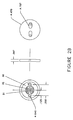
- the portable safety monitoring device 12 contains a pressure switch 25 as shown in Figure 2 having a housing 26 affixed to the outer casing 27 of the portable safety monitoring device 12 into which the pressure hose 18 is inserted.
- the pressure switch 25 has a movable relatively elastic conductive rubber plunger 28 and a printed circuit board 30 maintained a fixed distance apart in housing 26 during normal operation of the pressure switch 25.
- the printed circuit board 30 contains two etched wire conductors 31 and 32 in close proximity to one another as shown in Figure 2a and preferably in a serpentine arrangement. Wire leads 33 and 34 extend from the wire conductors 31 and 32 of the pressure switch 25.
- the elastic conductive rubber plunger 28 will expand in response to air pressure in the pressure hose 18 above a predetermined minimum level. Upon expansion the elastic conductive rubber plunger 28 makes physical contact with the printed circuit board 30 for connecting the wire conductors 31 and 32 to one another thereby closing the pressure switch 25.
- the pressure switch 25 is functionally represented as a manual switch in the electrical circuit schematic wiring diagram of Figure 3.
- the circuit as shown in Figure 3 includes a latching relay 40, a manually operated rotary switch 41, a power supply 42, a motion sensor 43 and a directional alarm sounder 44.
- a thermally operated switch 45 is optional.
- the circuit also has a microcomputer 47.
- the rotary switch 41 has an off position, an on position and an automatic position. In the on position the directional alarm sounder 44 is activated whereas in the automatic position the directional alarm sounder 44 is activated after the motion sensor 43 is activated. In the automatic or off positions the latching relay 40 will be activated when the portable safety monitoring device 12 is connected to an external SCBA with its pressurized air supply turned on.
- the latching relay 40 is activated the motion sensor 43 and the directional alarm sounder 44 remain in an operational mode and will cause an alarm should the operator remains inactive long enough to activate the motion sensor 43.
- the latching relay 40 is deactivated when the pressurized air supply from the SCBA is turned off and the rotary switch 41 is turned from off to automatic and back to off.
- the portable safety monitoring device 12 is always in the on mode by switching the rotary switch 41 to "ON".
- the portable safety monitoring device 12 may be disconnected from the SCBA and operated as an independent unit from the rotary switch 41.
- the portable safety monitoring device 12 operates through the rotary switch 41 in the automatic position or in on position independent of whether the latching relay was restored to the deactivated position or not provided the pressurized air supply from the SCBA has been disconnected or is turned off.
- the latching relay 40 is a conventional device which has open contacts 46 which close when the relay 40 is energized thereby holding the latching relay 40 in the activated position even if the pressure switch 25 opens. Once the latching relay 40 is activated power from the power supply 42 continues to be applied to the motion sensor 43 whether the manual rotary switch 41 is off or in the automatic position. Power is applied directly to the directional alarm sounder 44 in the rotary "on" position. Once power is removed from the latching relay 40 it deactivates.
- the directional alarm sounder 44 when activated delivers a directional sound alarm in the event the wearer becomes motionless for a fixed time period of e.g. 30 seconds. It may be activated directly by rotation of the manual switch 41 to the on position or through the activation of the motion sensor 43.
- any conventional motion sensor 43 may be used the preferred motion sensor is taught in US Patent No. 5,278,414 the disclosure of which is herein incorporated by reference and the preferred directional alarm is taught in US Patent No.4,962,159 the disclosure of which is also herein incorporated by reference.
- the motion sensor is an optical device consisting of a housing having a chamber which encloses a ball which freely moves in the chamber.
- Light is projected into the chamber along a first axis and is detected at a given angular axis relative to the first axis.
- the ball as it freely moves in the chamber obscures the detection of the light.
- the projected light is then turned on and off at a given frequency so that the output of the light detectors can be used to detect motion variances which affect ball movement. In this way when the motion of the wearer of unit 12 is not normal indicating a disabled wearer the output of the light detectors activates an alarm to produce directional sound so that disabled wearer may be readily found.
- the unit 12 may be activated when used in conjunction with an SCBA by sensing the presence of pressurized air or my be activated independent of the SCBA by rotating the manual switch 41 to the automatic position.
- Reference flow line 50 designates the manually operated independent alarm condition of the unit 12.
- the PASS may also be activated by having the SCBA pressure "ON” identified by reference flow line 51 or by the knob 41 moved to the automatic position identified by reference flow lines 52. If in the "ON" mode and the knob 41 is in the “ON” position the knob 41 has to be pushed down and turned to "OFF” to turn the PASS off as identified by reference flow line 53.
- a prealert condition is activated through the operation of the microprocessor 47 which monitors the state of the motion sensor 43 in order to give the operator a prealert signal through the directional sounder if inactivity, i.e. lack of movement is detected for a reduced time period.
- the PASS is put on “PRE ALERT” after 22 seconds of inactivity if in "AUTO” mode as indicated by reference flow line 56. If in “PRE ALERT” and movement occurs within 8 seconds the PASS is put in "AUTO” mode as indicated by reference flow line 57. If in “PRE ALERT” and no movement occurs within 8 seconds the PASS is put in the "ON” mode as indicated by reference flow line 58.
Landscapes
- Health & Medical Sciences (AREA)
- Pulmonology (AREA)
- General Health & Medical Sciences (AREA)
- Business, Economics & Management (AREA)
- Emergency Management (AREA)
- Respiratory Apparatuses And Protective Means (AREA)
Applications Claiming Priority (2)
| Application Number | Priority Date | Filing Date | Title |
|---|---|---|---|
| US606408 | 1990-10-31 | ||
| US08/606,408 US5757273A (en) | 1996-02-23 | 1996-02-23 | Multifunctional personal alert safety system |
Publications (2)
| Publication Number | Publication Date |
|---|---|
| EP0800844A2 true EP0800844A2 (de) | 1997-10-15 |
| EP0800844A3 EP0800844A3 (de) | 1999-01-13 |
Family
ID=24427842
Family Applications (1)
| Application Number | Title | Priority Date | Filing Date |
|---|---|---|---|
| EP97850024A Withdrawn EP0800844A3 (de) | 1996-02-19 | 1997-02-18 | Multifunktionelles persönliches Sicherheitsalarmsystem |
Country Status (2)
| Country | Link |
|---|---|
| US (1) | US5757273A (de) |
| EP (1) | EP0800844A3 (de) |
Cited By (5)
| Publication number | Priority date | Publication date | Assignee | Title |
|---|---|---|---|---|
| WO2001008752A1 (de) * | 1999-07-29 | 2001-02-08 | Msa Auer Gmbh | Warngerät für einen pressluftatmer |
| EP2229982A1 (de) * | 2009-03-19 | 2010-09-22 | Clipper Data Limited | Autonome Beatmungsvorrichtung und Steuerungssystem dafür |
| GB2496402A (en) * | 2011-11-09 | 2013-05-15 | Draeger Safety Uk Ltd | Monitoring apparatus |
| US9691259B2 (en) | 2012-03-29 | 2017-06-27 | Honeywell International, Inc. | Method to activate emergency alarm on a personal alarm safety system device |
| WO2021019348A1 (en) * | 2019-07-26 | 2021-02-04 | 3M Innovative Properties Company | Low pressure alarm for self-contained breathing apparatus |
Families Citing this family (6)
| Publication number | Priority date | Publication date | Assignee | Title |
|---|---|---|---|---|
| US6091331A (en) * | 1999-09-14 | 2000-07-18 | Bacou Usa Safety, Inc. | Emergency worker and fireman's dual emergency warning system |
| US6727805B2 (en) | 2002-05-14 | 2004-04-27 | Fire Factory, Llc | Signaling retention device |
| DE10314135B3 (de) * | 2003-03-24 | 2004-09-30 | Msa Auer Gmbh | Warnsystem für unter gefährlichen Bedingungen tätige Personen |
| ES2219186B1 (es) * | 2003-05-14 | 2006-01-16 | Antonio Perez Garcia | Equipo electronico de seguridad y control de personal. |
| US7548013B2 (en) * | 2006-03-14 | 2009-06-16 | Piezotech, Llc | High temperature piezo buzzer |
| US10328292B2 (en) * | 2014-08-27 | 2019-06-25 | Honeywell International Inc. | Multi-sensor based motion sensing in SCBA |
Citations (4)
| Publication number | Priority date | Publication date | Assignee | Title |
|---|---|---|---|---|
| EP0428131A2 (de) * | 1989-11-13 | 1991-05-22 | CAIRNS & BROTHER INCORPORATED | Druckanzeigevorrichtung für unabhängiges Atemgerät |
| US5278414A (en) * | 1992-01-09 | 1994-01-11 | Detex Corporation | Optical motion and angular position sensing method and sensor |
| US5438320A (en) * | 1993-04-09 | 1995-08-01 | Figgie International Inc. | Personal alarm system |
| US5492110A (en) * | 1994-12-23 | 1996-02-20 | Golden West Communications | Switched alert circuit for fireman's breathing system |
Family Cites Families (4)
| Publication number | Priority date | Publication date | Assignee | Title |
|---|---|---|---|---|
| WO1988006549A1 (en) * | 1987-03-03 | 1988-09-07 | Ernest Comerford | A dive parameter indicating assembly |
| US4926159A (en) * | 1988-07-15 | 1990-05-15 | Detex Corporation | Apparatus and method for the generation of directionally perceptible sound |
| US4914422A (en) * | 1989-09-14 | 1990-04-03 | Daniel Rosenfield | Temperature and motion sensor |
| US5317305A (en) * | 1992-01-30 | 1994-05-31 | Campman James P | Personal alarm device with vibrating accelerometer motion detector and planar piezoelectric hi-level sound generator |
-
1996
- 1996-02-23 US US08/606,408 patent/US5757273A/en not_active Expired - Fee Related
-
1997
- 1997-02-18 EP EP97850024A patent/EP0800844A3/de not_active Withdrawn
Patent Citations (4)
| Publication number | Priority date | Publication date | Assignee | Title |
|---|---|---|---|---|
| EP0428131A2 (de) * | 1989-11-13 | 1991-05-22 | CAIRNS & BROTHER INCORPORATED | Druckanzeigevorrichtung für unabhängiges Atemgerät |
| US5278414A (en) * | 1992-01-09 | 1994-01-11 | Detex Corporation | Optical motion and angular position sensing method and sensor |
| US5438320A (en) * | 1993-04-09 | 1995-08-01 | Figgie International Inc. | Personal alarm system |
| US5492110A (en) * | 1994-12-23 | 1996-02-20 | Golden West Communications | Switched alert circuit for fireman's breathing system |
Cited By (6)
| Publication number | Priority date | Publication date | Assignee | Title |
|---|---|---|---|---|
| WO2001008752A1 (de) * | 1999-07-29 | 2001-02-08 | Msa Auer Gmbh | Warngerät für einen pressluftatmer |
| EP2229982A1 (de) * | 2009-03-19 | 2010-09-22 | Clipper Data Limited | Autonome Beatmungsvorrichtung und Steuerungssystem dafür |
| GB2496402A (en) * | 2011-11-09 | 2013-05-15 | Draeger Safety Uk Ltd | Monitoring apparatus |
| GB2496402B (en) * | 2011-11-09 | 2016-02-24 | Draeger Safety Uk Ltd | Monitoring apparatus |
| US9691259B2 (en) | 2012-03-29 | 2017-06-27 | Honeywell International, Inc. | Method to activate emergency alarm on a personal alarm safety system device |
| WO2021019348A1 (en) * | 2019-07-26 | 2021-02-04 | 3M Innovative Properties Company | Low pressure alarm for self-contained breathing apparatus |
Also Published As
| Publication number | Publication date |
|---|---|
| EP0800844A3 (de) | 1999-01-13 |
| US5757273A (en) | 1998-05-26 |
Similar Documents
| Publication | Publication Date | Title |
|---|---|---|
| US6311779B2 (en) | Signalling fire extinguisher assembly | |
| US4803471A (en) | Ventilator monitor and alarm apparatus | |
| US5757273A (en) | Multifunctional personal alert safety system | |
| US4959637A (en) | Emergency signaling device | |
| US4418337A (en) | Alarm device | |
| US4990894A (en) | Ventilator monitor and alarm apparatus | |
| EP0886537B1 (de) | Verfahren und system zur überprüfung der funktonsfähigkeit eines atmungsgeräts | |
| EP2212870B1 (de) | Notsignal-armband | |
| US5625345A (en) | Fire safety apparatus | |
| US7450020B2 (en) | Signaling pressure detection assembly | |
| EP1803105B1 (de) | Warnungs-silencing bei niedrigem batteriestand in lebenserhaltenden vorrichtungen | |
| EP2645349B1 (de) | Verfahren zum Aktivieren eine Notfallalarms auf einer persönlichen Alarmsicherheitssystemvorrichtung | |
| CA2271469C (en) | Self contained breathing apparatus | |
| WO1997019726A9 (en) | Self-contained breathing apparatus having a personal alert safety system integrated therewith | |
| EP0873158A2 (de) | Autonomes tauchgerät mit darin integriertem persönlichen sicherheitsalarmsystem | |
| US5640148A (en) | Dual activation alarm system | |
| US5686884A (en) | Supervised alarm system | |
| US5682131A (en) | Retractable tamper resistant annunciator | |
| US4083041A (en) | Ground circuit monitor | |
| US5949337A (en) | Dual controlled personal alert safety system | |
| CN108248798B (zh) | 一种电动救生圈的报警方法及系统 | |
| US4931772A (en) | Safety monitor | |
| CA2379697A1 (en) | Warning device for a compressed air breathing apparatus | |
| US5365923A (en) | Sound responsive optical warning apparatus and method for SCBA | |
| WO1996036861A1 (en) | Pressure sensing valve cap that permits the passage of air |
Legal Events
| Date | Code | Title | Description |
|---|---|---|---|
| PUAI | Public reference made under article 153(3) epc to a published international application that has entered the european phase |
Free format text: ORIGINAL CODE: 0009012 |
|
| AK | Designated contracting states |
Kind code of ref document: A2 Designated state(s): DE FR GB IT SE |
|
| PUAL | Search report despatched |
Free format text: ORIGINAL CODE: 0009013 |
|
| AK | Designated contracting states |
Kind code of ref document: A3 Designated state(s): DE FR GB IT SE |
|
| STAA | Information on the status of an ep patent application or granted ep patent |
Free format text: STATUS: THE APPLICATION IS DEEMED TO BE WITHDRAWN |
|
| 18D | Application deemed to be withdrawn |
Effective date: 19990901 |