EP0800639B1 - Temperatursteuernde tiefsttemperaturbaueinheit - Google Patents
Temperatursteuernde tiefsttemperaturbaueinheit Download PDFInfo
- Publication number
- EP0800639B1 EP0800639B1 EP95944736A EP95944736A EP0800639B1 EP 0800639 B1 EP0800639 B1 EP 0800639B1 EP 95944736 A EP95944736 A EP 95944736A EP 95944736 A EP95944736 A EP 95944736A EP 0800639 B1 EP0800639 B1 EP 0800639B1
- Authority
- EP
- European Patent Office
- Prior art keywords
- temperature
- circuit
- high temperature
- package system
- substrate
- Prior art date
- Legal status (The legal status is an assumption and is not a legal conclusion. Google has not performed a legal analysis and makes no representation as to the accuracy of the status listed.)
- Expired - Lifetime
Links
Images

Classifications
-
- G—PHYSICS
- G05—CONTROLLING; REGULATING
- G05D—SYSTEMS FOR CONTROLLING OR REGULATING NON-ELECTRIC VARIABLES
- G05D23/00—Control of temperature
- G05D23/19—Control of temperature characterised by the use of electric means
- G05D23/1906—Control of temperature characterised by the use of electric means using an analogue comparing device
- G05D23/1912—Control of temperature characterised by the use of electric means using an analogue comparing device whose output amplitude can take more than two discrete values
-
- H—ELECTRICITY
- H10—SEMICONDUCTOR DEVICES; ELECTRIC SOLID-STATE DEVICES NOT OTHERWISE PROVIDED FOR
- H10N—ELECTRIC SOLID-STATE DEVICES NOT OTHERWISE PROVIDED FOR
- H10N60/00—Superconducting devices
- H10N60/80—Constructional details
- H10N60/81—Containers; Mountings
Definitions
- This invention relates to a cryogenic package System, and more specifically to a cryogenic package system for maintaining a high temperature superconductor circuit within a predetermined temperature range.
- the temperature in a cryogenic test chamber is maintained at a predetermined temperature range by regulating the temperature of a fluid supplied to the test chamber by a capillary tube.
- a magnetic field generator is maintained at a predetermined temperature range by regulating the temperature of a thermal shield surrounding the generator.
- a charge-coupled device package comprising a substrate of dielectric material and a charge-coupled device die mounted on one main face of the substrate.
- the substrate is placed in heat exchange relationships with a cold sink.
- a temperature sensor senses the temperature at a location on the main face that is in close proximity of the die.
- a film resistor is adhered to the opposite main face of the substrate and receives a current that depends upon the temperature sensed by the sensor.
- U.S. Patent No. 5,161,609 there is disclosed a method and an apparatus for high speed temperature regulation of elements in thermal contact with a fluid contained in liquid-vapor equilibrium inside an enclosure which is closed in sealed manner and which is provided with thermal insulation.
- a temperature regulation is provided by means of an external heat source imposing a reference temperature to the fluid contained inside the enclosure and causing a corresponding variation in the temperature of the elements by changing the phase of the fluid.
- objects are typically maintained within a predetermined temperature range by using a heating or cooling element to regulate the temperature of the cryogenic environment or materials surrounding the object. While this approach is sufficient for maintaining the object within a relatively wide temperature range, there are certain applications that cannot tolerate such a wide temperature range, because these certain applications depend on high performance circuits that are very temperature sensitive.
- high temperature is used as a relative term, and generally refers to temperatures above 30 Kelvin (K), and more particularly, refers to temperatures above the boiling point of liquid nitrogen, which is approximately 77 K. To put Kelvins into a proper frame of reference, 77 K is -196°C (approximately -320° Fahrenheit (F)). Thus, even these so called “high temperature” superconductor circuits operate at extremely cold temperatures that require highly specialized equipment and control techniques for optimum performance.
- Cryogenic operating temperatures are typically achieved by using cryogenic coolants stored in dewars to cool the environment surrounding the object.
- cryogenic coolants stored in dewars to cool the environment surrounding the object.
- liquid nitrogen as a cryogenic coolant provides an acceptable operating temperature of approximately 77 K, or -196°C (-320° F).
- high temperature superconductor circuits are sensitive to temperature fluctuations far below their transition temperature. Furthermore, high temperature superconductor circuits are especially sensitive to fluctuations in their operating temperature when they are operating near their transition temperature, which is the temperature at which a high temperature superconductor circuit switches between a state of normal resistivity and a state of superconductivity.
- the cryogenic package system of the present invention provides a novel configuration for maintaining an object, such as a high temperature superconductor circuit, within a narrow predetermined temperature range.
- the cryogenic package system of the present invention integrates a high temperature superconductor circuit and a heating element directly onto a common substrate, and then controls the heating element by monitoring the operating temperature of the high temperature superconductor circuit itself, rather than by merely monitoring the temperature of the cryogenic environment or materials surrounding the high temperature superconductor circuit.
- the cryogenic temperature control system has an improved ability to control the temperature fluctuations of the circuit with greater precision and with much shorter time constants.
- the cryogenic package system of the present invention comprises a control circuit, a temperature sensor, and the heating element interacting in a closed loop temperature control system.
- the temperature sensor monitors the operating temperature of the high temperature superconductor circuit, and transmits this measured temperature reading to the control circuit.
- the control circuit activates or deactivates the heating element accordingly. This in turn causes the operating temperature of the circuit to be modified, thereby causing the temperature sensor to send updated temperature readings to the control circuit.
- This feedback control process maintains the operating temperature of the circuit within an acceptable range of approximately plus or minus 0.1 K of a predetermined operating temperature.
- the heating element transfers its heat more efficiently to the circuit. If the heating element is located far from the circuit, then the heating element has to compete with and partially overcome the cooling effect of a cold head in order to sufficiently heat the cryogenic environment surrounding the circuit in an effort to raise the operating temperature of the circuit. As a result, the typical approach of heating the surrounding cryogenic environment of the object is less efficient than the cryogenic package system of the present invention which is designed to heat the object more directly. This is especially important when the cold head has a limited cooling capacity.
- the predetermined operating temperature of the circuit is slightly higher than the temperature of the cold head.
- the heating element being in communication with the control circuit, can offset the cooling effect of the cold head if the operating temperature is too low, and can turn off the heating element to let the cold head cool the circuit if the operating temperature is too high.
- thermal paths and thermal time constants are reduced significantly, thereby increasing heater response time while decreasing heat input to the cold head which reduces efficiency.
- cool down time of the cryogenic package system is also reduced as a result of the reduced thermal mass of the substrate containing the high temperature superconductor circuit and heating element. This allows for an improved coarse temperature control of the high temperature superconductor circuit, since there is less thermal mass that the cold head needs to cool.
- the cryogenic package system of the present invention minimizes the number of connections required between the cryogenic environment and an ambient, or room temperature, or non-cryogenic environment that surrounds the cryogenic environment. This reduces the conductive thermal heat load that is conducted from the ambient environment via control circuit connecting cables to the cold head. This is critical to systems with limited cooling capabilities.
- the substrate is placed in a housing that is attached to a cold head via thermal isolators of various thickness, cross-sectional area, and thermal conductivity.
- the ability to vary the thickness, cross-sectional area, and thermal conductivity of the thermal isolators serves as a coarse method of adjusting the temperature gradient between the cold head and the high temperature superconductor circuit so as to minimize heat input from the heating element to the cold head, such that the heating element heat is transferred more efficiently to the circuit rather than the cold head.
- the heating element is formed from a thin film resistor material.
- the resistor material comprises nichrome, tantalum nitride, or other equivalent materials that function well in cryogenic environments.
- a patterned thin film heating element minimizes outgassing constraints, since no adhesives are used as in conventional die attach methods.
- Various elements on the substrate such as the control circuit or the high temperature superconductor circuit, are connected to the ambient environment by cables that are capable of transferring power and/or information.
- these cables conduct heat from the ambient environment to the cryogenic environment, thereby adding to the thermal load of the cryogenic package system. Therefore, in a preferred embodiment, a cable thermal strap is used to transfer heat conducted by the cable away from the high temperature circuit and to the cold head.
- An additional object of the present invention is to provide a cryogenic package system for a high temperature superconductor circuit, whereby the temperature of the high temperature superconductor circuit is maintained within a predetermined temperature range by monitoring the temperature of the high temperature superconductor circuit itself.
- Yet another object of the present invention is to provide a cryogenic package system for a high temperature superconductor circuit, whereby the temperature of the high temperature superconductor circuit is maintained at a predetermined temperature with a range of temperature fluctuations not to exceed ⁇ 0.1 K.
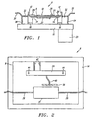
- FIG. 1 shows a preferred embodiment of a temperature controlled cryogenic package system 6 of the present invention. It is understood that, for illustrative purposes, the various elements are not shown in proportion.
- a substrate 8 for receiving a high temperature superconductor circuit 10 is placed within a circuit housing 12, with the high temperature superconductor circuit 10 being thermally isolated from the circuit housing 12 by a circuit thermal isolator 14.
- the circuit housing 12 containing the high temperature superconductor circuit 10 is placed upon a cold head 16, also known as a cooling interface.
- the circuit housing 12 is thermally isolated from the cold head 16 by a housing thermal isolator 18.
- the cooling effect of the cold head 16 on the high temperature superconductor 10 can be controlled by varying the thickness, cross-sectional area, and/or thermal conductivity of the circuit thermal isolater 14 and/or the housing thermal isolator 18.
- heating the high temperature superconductor circuit 10 can be made more efficient by reducing the amount of heat that is inputted to the cold head 16 by directing the heat more specifically to the high temperature superconductor circuit 10.
- a cooler cold finger 20 Attached to the cold head 16 is a cooler cold finger 20, which in a preferred embodiment comprises a liquid nitrogen reservoir, or another type of cooler, such as a Stirling cycle cooler (not shown).
- a cold finger to cool a cold head is well known in the art, and is not discussed in further detail herein.
- a heating element 22 is placed on the same substrate 8 as the high temperature superconductor circuit 10.
- a control circuit 24 is placed on this substrate 8 adjacent to the high temperature superconductor circuit 10, and the control circuit 24 is capable of being in electrical communication with the heating element 22 via a first electrical connection 26.
- the control circuit 24 can be placed on another substrate in an ambient environment separate from the high temperature superconductor circuit 10, by placing the control circuit 24 on the same substrate 8 as the high temperature superconductor circuit 10, fewer connections between the cryogenic environment and the ambient environment are required (and thus fewer discontinuities in environmental temperature exist), thereby reducing the conduction of heat from the ambient environment to the cryogenic environment. In a preferred embodiment, only power connections are required.
- a bondwire 28 is used to electrically connect the high temperature superconductor circuit 10 to a cable 30 via a cable interface 32.
- the cable interface 32 provides a connection from the cable 30 to the high temperature superconductor circuit 10.
- a cable thermal strap 34 is connected from the cable 30 to the cold head 16.
- the cable thermal strap 34 is used to transfer most of the heat conducted by the cable 30 from the ambient environment to the cold head 16, rather than letting the conducted heat dissipate into the cryogenic environment surrounding the high temperature superconductor circuit 10, which would affect the stability of the desired operating temperature of the high temperature superconductor circuit 10.
- FIG. 2 is a top view of the cryogenic package system 6 showing the high temperature superconductor circuit 10 and temperature control elements comprising the heating element 22 (as shown in FIG. 1), the control circuit 24, and a temperature sensor 38.
- the high temperature superconductor circuit 10 is connected to the cable interface 32 (as shown in FIG. 1) via the bondwire 28.
- the temperature sensor 38 is placed in thermal proximity with the high temperature superconductor circuit 10, and the temperature sensor 38 is capable of being electrically connected to the control circuit 24 via a second electrical connection 40.
- the control circuit 24 comprises a third electrical connection 42 for allowing power and/or information to be transferred between the control circuit 24 in the cryogenic environment and various components in the ambient environment. For example, a bias signal from an ambient environment component to the control circuit 24 in the cryogenic environment can be transferred via the third electrical connection 42.
- the substrate 8 has at least one via hole 44, shown through the control circuit 24 in FIG. 2, that allows for the first electrical connection 26 (as shown in FIG. 1) to be connected from the control circuit 24 on a top portion of the substrate 8 to the heating element 22 (as shown in FIG. 1) located on a bottom portion of the substrate 8.
- FIG. 3 a preferred embodiment of the substrate 8 is shown. Placement of certain elements, such as the control circuit 24, on the substrate 8 provides certain benefits as discussed above. It is further understood that the various elements depicted in FIG. 3 are, for illustrative purposes, not shown in realistic proportion.
- the heating element 22 appears to be an attachment to the substrate 8
- the heating element 22, described as a resistor material 52 appears to be integral to the substrate 8.
- the heating element 22, or resistor material 52 is integral to the substrate 8.
- a gold ground plane layer 48 is formed on a first ceramic layer 50, and the high temperature superconductor circuit 10 is formed on the gold ground plane layer 48.
- a layer of resistor material 52 that serves as the heating element 22.
- the resistor material 52 layer is coated with a passivation layer 54 to prevent shorting of the resistor material 52.
- Adjacent to the high temperature superconductor circuit 10 is a second ceramic layer 56 covered by a gold signal plane layer 58.
- a third ceramic layer 60 is covered by a layer of Ni/Au 62, and is formed on the gold signal plane layer 58.
- These layers provide protection and isolation for the high temperature superconductor circuit 10, as well as an interface path between the high temperature superconductor circuit 10 and elements outside of the cryogenic package system 6, in a manner well known in the art.
- Constructing the substrate 8 from a material, such as alumina or magnesium oxide, with high thermal conductivity, high modulus of elasticity, high dielectric constant, and minimized mass provides the following benefits: (i) reduces cool down time, (ii) provides a good thermal path between the heating element 22 and the high temperature superconductor circuit 10, (iii) takes advantage of existing manufacturing technologies, (iv) is a lower-cost alternative to machined packages, (v) reduces the time constant, and (vi) provides a matched coefficient of thermal expansion between the high temperature superconductor circuit 10 and the cryogenic package system 6.
- FIG. 4 is schematic representation of a closed loop temperature control system located on the substrate 8 comprising the high temperature superconductor circuit 10, the heating element 22, the temperature sensor 38, and the control circuit 24.
- the control circuit 24 comprises a comparator 66.
- a first voltage source 63 generates a stable reference voltage 64, or signal, corresponding to a predetermined temperature.
- the reference voltage 64 is provided as an input to a positive input of the comparator 66, and is either a fixed value or an adjustable value depending upon the application. The value of the reference voltage 64 may be adjusted to correspond to various different desired predetermined temperatures.
- the comparator 66 compares the reference voltage 64 with an amplified circuit temperature voltage 80 that is provided as an input to a negative input of the comparator 66, and then the comparator 66 outputs an error voltage 68 that represents the difference between the desired predetermined temperature and a sensed high temperature superconductor circuit 10 temperature.
- a positive or negative error voltage 68 is generated if the operating temperature of the high temperature superconductor circuit 10 deviates from the predetermined temperature, and approaches either the upper or lower range of the predetermined temperature range.
- the design and response time of the closed loop temperature control system is such that the temperature range will not deviate by more than plus or minus 0.1 K from the predetermined temperature.
- the error voltage 68 is positive, meaning that the temperature of the high temperature superconductor circuit 10 is lower than the desired predetermined temperature
- the error voltage 68 is amplified by a first amplifier 70 in order to drive sufficient current through the resistor material 52, also referred to as the heating element 22.
- the current is transferred from the control circuit 24 to the heating element 22 via the first electrical connection 26, thereby causing the heating element 22 to generate heat.
- the closed loop temperature control system responds accordingly by turning the heating element 22 on again. It is understood that, depending upon the magnitude of the positive error voltage 68, the amount of heat generated by the heating element 22 can be varied accordingly.
- the first amplifier 70 cuts off the current flow to the resistor material 52, thereby turning off the heating element 22 and allowing the high temperature superconductor circuit 10 to be cooled back down toward the predetermined temperature by the cold head 16 (as shown in FIG. 1).
- Closed loop equilibrium is established when the amplified circuit temperature voltage 80 is equal to the reference voltage 64 such that the error voltage 68 output from the comparator 66 approaches zero. This means that the sensed temperature of the high temperature superconductor circuit 10 is equal to the predetermined temperature, and therefore, the current flow to the heating element 22 is cut off, thereby turning off the heating element 22.
- the total loop gain of the closed loop system is set to achieve a stable critically damped temperature control system.
- the temperature sensor 38 comprises a silicon junction transistor, or diode, biased with a current source 72 that is powered by a second voltage source 74. Since the temperature sensor's 38 junction voltage 82 varies in a predictable manner with respect to the temperature of the object that the temperature sensor 38 is sensing, the temperature sensor 38 provides a changing circuit temperature voltage 76 that corresponds to changes in the sensed temperature of the high temperature superconductor circuit 10. The circuit temperature voltage 76 is amplified by a second amplifier 78, and the second amplifier 78 outputs the amplified circuit temperature voltage 80. The amplified circuit temperature voltage 80 is then, as discussed above, provided as an input to the negative input of the comparator 66.
- circuit thermal isolator 14 and the housing thermal isolator 18 can be combined to form a single integrated thermal isolator unit.
- circuit housing 12 can be pivotally or removably extended over the top of the high temperature superconductor circuit 10 to act as a protective lid.
Landscapes
- Physics & Mathematics (AREA)
- General Physics & Mathematics (AREA)
- Engineering & Computer Science (AREA)
- Automation & Control Theory (AREA)
- Containers, Films, And Cooling For Superconductive Devices (AREA)
- Control Of Temperature (AREA)
- Devices That Are Associated With Refrigeration Equipment (AREA)
Claims (12)
- Temperaturgeregeltes kryogenes auf-Platten-montiertes-System (6) aufweisend ein Substrat (8), welches einen Hochtemperatursupraleiter-Schaltkreis (10) aufweist, einen mittels eines Kältefingers (20) gekühlten Kälte-Kopf (16) zum Kühlen des Hochtemperatursupraleiter-Schaltkreises (10) und
ein Temperaturregelungs-system, welches aufweist:wobei das Temperaturregelungs-System derart eingerichtet ist und eine Antwortzeit hat, dass das Halten des Hochtemperatursupraleiter-Schaltkreis (10) auf einer Temperatur innerhalb eines Bereiches, welcher eine maximale Abweichung von etwa 0,1K von einer vorgegebenen Temperatur aufweist, ermöglicht wird, wobei die Temperatur leicht höher als die des Kältekopfes (16) ist, undeinen Temperatursensor (38) in thermischer Nähe zu dem Hochtemperatursupraleiter-Schaltkreis (10) zum Erfassen einer Betriebstemperatur des Hochtemperatursupraleiter-Schaltkreises (10) und zum Übermitteln der Temperatur an einen Regelungs-Schaltkreis (24),ein auf dem Substrat (8) ausgebildetes Heizelement (22) zum Reagieren auf die Regelungs-Schaltkreis-Befehle zum Heizen des Hochtemperatursupraleiter-Schaltkreises (10), undden Regelungs-Schaltkreis (24), welcher in Reaktion auf einen Eingang von dem Temperatursensor (38) des Aktivierens und Deaktivierens des Heizelements (22) fähig ist,
wobei der Regelungs-Schaltkreis (24) auf dem Substrat (8) angeordnet ist. - Temperaturgeregeltes kryogenes auf-Platten-montiertes-System (6) gemäß Anspruch 1, weiterhin aufweisend:ein Schaltkreis-Gehäuse (12) zum Aufnehmen des Substrats (8) und einen thermischen Isolator (14) zum thermischen Isolieren des Hochtemperatursupraleiter-Schaltkreises (10) von dem Kälte-Kopf (16), wobei das Schaltkreis-Gehäuse (12) mittels des thermischen Isolator (14) an den Kälte-Kopf (16) gekoppelt ist.
- Temperaturgeregeltes kryogenes auf-Platten-montiertes-System (6) gemäß Anspruch 2, wobei das Verwenden einer vorgegebenen thermischen Impedanz für den thermischen Isolator (14) eine grobe Temperaturregelung der Betriebstemperatur ermöglicht.
- Temperaturgeregeltes kryogenes auf-Platten-montiertes-System (6) gemäß Anspruch 2, welches weiterhin ein Kabel (30) zum Übertragen von Information zwischen dem Hochtemperatursupraleiter-Schaltkreis (10) und einer umgebenden Umwelt aufweist.
- Temperaturgeregeltes kryogenes auf-Platten-montiertes-System (6) gemäß Anspruch 4, welches weiterhin ein thermisches Koppelkabel (34) zum Übertragen geleiteter Umgebungswärme von der umgebenden Umwelt zu dem Kälte-Kopf (16) aufweist.
- Temperaturgeregeltes kryogenes auf-Platten-montiertes-System (6) gemäß Anspruch 1, wobei das Substrat (8) aufweist:eine auf einer ersten Seite einer ersten Keramikschicht (50) ausgebildete Gold-Erdungsebene-Schicht (48),einen auf der Gold-Erdungsebene (48) ausgebildeten Hochtemperatursupraleiter-Schaltkreis (10), undeine Widerstands-Material-Schicht (52), welche auf einer zweiten Seite der ersten Keramikschicht (50) ausgebildet ist, wobei die Widerstands-Material-Schicht (52) mittels einer Passivierungsschicht (54) beschichtet ist, um Kurzschließen der Widerstands-Material-Schicht (52) zu verhindern.
- Temperaturgeregeltes kryogenes auf-Platten-montiertes-System (6) gemäß Anspruch 6, wobei das Substrat (8) weiterhin aufweist:eine zweite Keramikschicht (56) welche benachbart zu dem Hochtemperatursupraleiter-Schaltkreis (10) ausgebildet ist und welche mittels einer Gold-Signalebene-Schicht (58) bedeckt ist, undeine dritte Keramikschicht (60), welche mittels einer Ni/Au-Schicht (62) bedeckt ist, welche auf der Gold-Signalebene-Schicht (58) ausgebildet ist.
- Temperaturgeregeltes kryogenes auf-Platten-montiertes-System (6) gemäß Anspruch 1, wobei das Substrat (8) zumindest ein Kontaktloch (44) durch das Substrat (8) hindurch aufweist, zum elektrischen Koppeln des Heizelements (22) mit dem Regelungs-Schaltkreis (24).
- Temperaturgeregeltes kryogenes auf-Platten-montiertes-System (6) gemäß Anspruch 1, wobei der Regelungs-Schaltkreis (24) einen Komparator (66) zum Vergleichen einer Temperatur-Spannung (76) von dem Temperatursensor (38) und einer Referenzspannung (64) von einer Spannungsquelle (63) aufweist, wobei die Temperatur-Spannung (76) die Betriebstemperatur des Hochtemperatursupraleiter-Schaltkreises (10) widerspiegelt und die Referenzspannung (64) die vorgegebene Temperatur widerspiegelt.
- Temperaturgeregeltes kryogenes auf-Platten-montiertes-System (6) gemäß Anspruch 1, wobei der Temperatursensor (38) einen Silizium-Flächentransistor aufweist.
- Temperaturgeregeltes kryogenes auf-Platten-montiertes-System (6) gemäß Anspruch 9, weiterhin aufweisend
ein Schaltkreis-Gehäuse (12) zum Aufnehmen des Substrats (8),
einen thermischen Isolator (14) zum thermischen Isolieren des Hochtemperatursupraleiter-Schaltkreises (10) von dem Kälte-Kopf (16), wobei das Schaltkreis-Gehäuse (12) mittels des thermischen Isolators (14) an den Kälte-Kopf (16) gekoppelt ist, wobei das Verwenden einer vorgegebenen thermischen Impedanz für den thermischen Isolator (14) eine grobe Temperaturregelung der Betriebstemperatur ermöglicht,
ein Kabel (30) zum Übertragen von Information zwischen dem Hochtemperatursupraleiter-Schaltkreis (10) und einer nicht kryogenen Umwelt, und
ein thermisches Koppelband (34) zum Übertragen geleiteter Umgebungswärme von der nicht kryogenen Umwelt zu dem Kälte-Kopf (16). - Ein Verfahren zum Regeln einer Betriebstemperatur eines Hochtemperatursupraleiter-Schaltkreises (10), welcher auf einen gemeinsamen Substrat (8) mit einem Temperatursensor (38), einem Temperatur Regelungs-Schaltkreis (24), einem Heizelement (22) und einem Kälte-Kopf (16) ausgebildet ist, welcher mittels eines Kältefingers (20) gekühlt wird, zum Kühlen des Hochtemperatursupraleiter-Schaltkreises (10), welches die folgenden Schritte aufweist:a) Überwachen der Betriebstemperatur des Hochtemperatursupraleiter-Schaltkreises (10) mittels des Temperatursensors (38),b) Bereitstellen einer erfassten Betriebstemperatur von dem Temperatursensor (38) für den Regelungs-Schaltkreis (24),c) Vergleichen der erfassten Betriebstemperatur mit einer Referenztemperatur mittels des Regelungs-Schaltkreises (24),d) Regeln des Heizelements (22) mittels des Regelungs-Schaltkreises (24), welcher derart eingerichtet ist und eine Antwortzeit hat, dass das Halten des Hochtemperatursupraleiter-Schaltkreises (10) auf einer Temperatur innerhalb eines vorgegebenen Bereiches ermöglicht wird, wobei der vorgegebene Bereich eine maximale Abweichung von etwa 0,1K von einer vorgegebenen Temperatur aufweist, zu halten, und wobei der Hochtemperatursupraleiter-Schaltkreises (10) auf einer leicht höheren Temperatur als die des Kälte-Kopfes (16) gehalten wird, unde) Wiederholen der Schritte a) bis d).
Applications Claiming Priority (3)
| Application Number | Priority Date | Filing Date | Title |
|---|---|---|---|
| US08/369,004 US5818097A (en) | 1995-01-05 | 1995-01-05 | Temperature controlling cryogenic package system |
| US369004 | 1995-01-05 | ||
| PCT/US1995/016921 WO1996021129A1 (en) | 1995-01-05 | 1995-12-26 | Temperature controlling cryogenic package system |
Publications (3)
| Publication Number | Publication Date |
|---|---|
| EP0800639A1 EP0800639A1 (de) | 1997-10-15 |
| EP0800639A4 EP0800639A4 (de) | 1999-01-13 |
| EP0800639B1 true EP0800639B1 (de) | 2003-03-05 |
Family
ID=23453656
Family Applications (1)
| Application Number | Title | Priority Date | Filing Date |
|---|---|---|---|
| EP95944736A Expired - Lifetime EP0800639B1 (de) | 1995-01-05 | 1995-12-26 | Temperatursteuernde tiefsttemperaturbaueinheit |
Country Status (7)
| Country | Link |
|---|---|
| US (1) | US5818097A (de) |
| EP (1) | EP0800639B1 (de) |
| JP (1) | JPH10512102A (de) |
| AT (1) | ATE233884T1 (de) |
| CA (1) | CA2209627A1 (de) |
| DE (1) | DE69529843T2 (de) |
| WO (1) | WO1996021129A1 (de) |
Families Citing this family (12)
| Publication number | Priority date | Publication date | Assignee | Title |
|---|---|---|---|---|
| US6060692A (en) * | 1998-09-02 | 2000-05-09 | Cts Corporation | Low power compact heater for piezoelectric device |
| US6098409A (en) * | 1998-12-03 | 2000-08-08 | Superconductor Technologies, Inc. | Temperature control of high temperature superconducting thin film filter subsystems |
| US6562030B1 (en) * | 1999-04-06 | 2003-05-13 | Cryocath Technologies Inc. | Heater control of cryocatheter tip temperature |
| JP2002168547A (ja) * | 2000-11-20 | 2002-06-14 | Global Cooling Bv | 熱サイホンによるcpu冷却装置 |
| US6664511B2 (en) * | 2001-07-09 | 2003-12-16 | Jds Uniphase Corporation | Package for optical components |
| JP2011513755A (ja) | 2008-03-07 | 2011-04-28 | カリフォルニア インスティテュート オブ テクノロジー | 磁性粒子検出を基本とする実効インダクタンスの変化 |
| US8274021B2 (en) * | 2008-03-07 | 2012-09-25 | California Institute Of Technology | Fully integrated temperature regulator for biochemical applications |
| US9599591B2 (en) | 2009-03-06 | 2017-03-21 | California Institute Of Technology | Low cost, portable sensor for molecular assays |
| US8274301B2 (en) * | 2009-11-02 | 2012-09-25 | International Business Machines Corporation | On-chip accelerated failure indicator |
| US9327847B2 (en) * | 2012-08-16 | 2016-05-03 | Minus K. Technology, Inc. | Thermal straps for spacecraft |
| US11879789B2 (en) | 2019-07-02 | 2024-01-23 | International Business Machines Corporation | On-chip thermometer for superconducting quantum computing devices |
| US11674854B2 (en) | 2019-07-02 | 2023-06-13 | International Business Machines Corporation | Mapping temperature distribution in superconducting devices |
Family Cites Families (41)
| Publication number | Priority date | Publication date | Assignee | Title |
|---|---|---|---|---|
| US3395265A (en) * | 1965-07-26 | 1968-07-30 | Teledyne Inc | Temperature controlled microcircuit |
| US3393870A (en) * | 1966-12-20 | 1968-07-23 | Texas Instruments Inc | Means for controlling temperature rise of temperature stabilized substrates |
| US3667246A (en) * | 1970-12-04 | 1972-06-06 | Atomic Energy Commission | Method and apparatus for precise temperature control |
| US3809931A (en) * | 1973-03-19 | 1974-05-07 | Us Navy | Temperature-stabilized transducer device |
| US3887785A (en) * | 1974-08-29 | 1975-06-03 | Us Air Force | Temperature controlled hybrid oven |
| US4118947A (en) * | 1977-05-19 | 1978-10-10 | Selenia-Industrie Elettroniche Associate S.P.A. | Low thermal loss cryogenic containers for infrared radiation detecting devices, with integrated feed-through connections |
| US4194119A (en) * | 1977-11-30 | 1980-03-18 | Ford Motor Company | Self-adjusting cryogenic thermal interface assembly |
| DE2944464A1 (de) * | 1979-11-03 | 1981-05-14 | C. Reichert Optische Werke Ag, Wien | Einrichtung zur kryosubstitution kleiner biologischer objekte fuer mikroskopische, insbesondere elektronenmikroskopische untersuchungen |
| US4369636A (en) * | 1981-07-06 | 1983-01-25 | General Atomic Company | Methods and apparatus for reducing heat introduced into superconducting systems by electrical leads |
| US4576010A (en) * | 1983-10-18 | 1986-03-18 | Nhy-Temp, Inc. | Cryogenic refrigeration control system |
| US4546614A (en) * | 1984-04-13 | 1985-10-15 | General Dynamics Pomona Division | Precooled detector leads |
| US4712607A (en) * | 1984-11-09 | 1987-12-15 | Freeze Control Pty. Ltd. | Cryosystem for biological material |
| US4739382A (en) * | 1985-05-31 | 1988-04-19 | Tektronix, Inc. | Package for a charge-coupled device with temperature dependent cooling |
| JPS6220303A (ja) * | 1985-07-19 | 1987-01-28 | Hitachi Ltd | 強制冷却超電導コイル装置 |
| US4827217A (en) * | 1987-04-10 | 1989-05-02 | Biomagnetic Technologies, Inc. | Low noise cryogenic apparatus for making magnetic measurements |
| DE3854679T2 (de) * | 1987-04-22 | 1996-07-18 | Sharp K.K., Osaka | Supraleitfähiges Gerät. |
| US4848093A (en) * | 1987-08-24 | 1989-07-18 | Quantum Design | Apparatus and method for regulating temperature in a cryogenic test chamber |
| US4930318A (en) * | 1988-07-05 | 1990-06-05 | General Electric Company | Cryocooler cold head interface receptacle |
| US4876413A (en) * | 1988-07-05 | 1989-10-24 | General Electric Company | Efficient thermal joints for connecting current leads to a cryocooler |
| US4895831A (en) * | 1988-07-05 | 1990-01-23 | General Electric Company | Ceramic superconductor cryogenic current lead |
| US4872322A (en) * | 1988-09-02 | 1989-10-10 | General Electric Company | Power operated contact apparatus for superconductive circuit |
| FR2638023B1 (fr) * | 1988-10-13 | 1992-07-31 | Telecommunications Sa | Dispositif cryostatique pour detecteur de rayonnements |
| US4918312A (en) * | 1988-11-23 | 1990-04-17 | Santa Barbara Research Center | Dewar coldfinger |
| EP0372108B1 (de) * | 1988-12-05 | 1994-08-31 | Heinz Karl Diedrich | Vakuumbehälter zum kryogenischen Kühlen einer Packung für eine elektronische Anordnung |
| US4970868A (en) * | 1989-06-23 | 1990-11-20 | International Business Machines Corporation | Apparatus for temperature control of electronic devices |
| GB8920345D0 (en) * | 1989-09-08 | 1989-10-25 | Oxford Advanced Tech | Magnetic field generating system |
| US4950901A (en) * | 1989-11-06 | 1990-08-21 | Gatan, Incorporated | Specimen cooling holder for side entry transmission electron microscopes |
| US4955204A (en) * | 1989-11-09 | 1990-09-11 | The Regents Of The University Of California | Cryostat including heater to heat a target |
| US5173620A (en) * | 1989-12-15 | 1992-12-22 | Fujitsu Limited | Device for eliminating trap of magnetic flux in a superconduction circuit |
| GB2247942B (en) * | 1990-09-05 | 1994-08-03 | Mitsubishi Electric Corp | Cryostat |
| US5309090A (en) * | 1990-09-06 | 1994-05-03 | Lipp Robert J | Apparatus for heating and controlling temperature in an integrated circuit chip |
| US5212626A (en) * | 1990-11-09 | 1993-05-18 | International Business Machines Corporation | Electronic packaging and cooling system using superconductors for power distribution |
| JPH04245113A (ja) * | 1991-01-31 | 1992-09-01 | Sumitomo Electric Ind Ltd | 酸化物超電導材料の製造方法 |
| US5196395A (en) * | 1991-03-04 | 1993-03-23 | Superconductor Technologies, Inc. | Method for producing crystallographic boundary junctions in oxide superconducting thin films |
| US5177054A (en) * | 1991-04-08 | 1993-01-05 | Emerson Electric Co. | Flux trapped superconductor motor and method therefor |
| US5328893A (en) * | 1991-06-24 | 1994-07-12 | Superconductor Technologies, Inc. | Superconducting devices having a variable conductivity device for introducing energy loss |
| US5193349A (en) * | 1991-08-05 | 1993-03-16 | Chicago Bridge & Iron Technical Services Company | Method and apparatus for cooling high temperature superconductors with neon-nitrogen mixtures |
| US5260266A (en) * | 1992-02-10 | 1993-11-09 | General Electric Company | High-TC superconducting lead assembly in a cryostat dual penetration for refrigerated superconductive magnets |
| US5260575A (en) * | 1993-03-10 | 1993-11-09 | Mitsubishi Denki Kabushiki Kaisha | Infrared detector |
| US5323293A (en) * | 1992-12-18 | 1994-06-21 | International Business Machines Corporation | Arrangement for placing central processors and memory in a cryo cooled chamber |
| US5424510A (en) * | 1993-08-27 | 1995-06-13 | Analog Devices Inc. | Circuit and method of providing thermal compensation for a transistor to minimize offset voltage due to self-heating of associated devices |
-
1995
- 1995-01-05 US US08/369,004 patent/US5818097A/en not_active Expired - Fee Related
- 1995-12-26 EP EP95944736A patent/EP0800639B1/de not_active Expired - Lifetime
- 1995-12-26 WO PCT/US1995/016921 patent/WO1996021129A1/en not_active Ceased
- 1995-12-26 AT AT95944736T patent/ATE233884T1/de not_active IP Right Cessation
- 1995-12-26 JP JP8521138A patent/JPH10512102A/ja not_active Ceased
- 1995-12-26 CA CA002209627A patent/CA2209627A1/en not_active Abandoned
- 1995-12-26 DE DE69529843T patent/DE69529843T2/de not_active Expired - Fee Related
Also Published As
| Publication number | Publication date |
|---|---|
| JPH10512102A (ja) | 1998-11-17 |
| ATE233884T1 (de) | 2003-03-15 |
| EP0800639A4 (de) | 1999-01-13 |
| CA2209627A1 (en) | 1996-07-11 |
| EP0800639A1 (de) | 1997-10-15 |
| DE69529843D1 (de) | 2003-04-10 |
| DE69529843T2 (de) | 2004-03-04 |
| US5818097A (en) | 1998-10-06 |
| WO1996021129A1 (en) | 1996-07-11 |
Similar Documents
| Publication | Publication Date | Title |
|---|---|---|
| EP0800639B1 (de) | Temperatursteuernde tiefsttemperaturbaueinheit | |
| US5188286A (en) | Thermoelectric piezoelectric temperature control | |
| US5704213A (en) | Method and apparatus for controlling the temperature of a device using independent multi-stage thermoelectric coolers | |
| WO1996021129A9 (en) | Temperature controlling cryogenic package system | |
| US5603220A (en) | Electronically controlled container for storing temperature sensitive material | |
| JP5000803B2 (ja) | 電子デバイスの速応温度反復制御を液体を利用して広範囲に行うための装置、方法 | |
| US6112525A (en) | Cooling unit | |
| CA1195908A (en) | Analytical instrument reactor temperature regulator | |
| US4324285A (en) | Apparatus for heating and cooling devices under test | |
| US6147795A (en) | Retrofit heater for erbium fiber in an erbium-doped fiber amplifier (EDFA) | |
| US3431392A (en) | Internally heated crystal devices | |
| EP0071696B1 (de) | Magnetkopf-Zusammenbau | |
| US4567773A (en) | Pressure transducer system | |
| US5857342A (en) | Temperature controlling cryogenic package system | |
| US4362023A (en) | Thermoelectric refrigerator having improved temperature stabilization means | |
| US2967924A (en) | Stable temperature reference for instrument use | |
| GB2097184A (en) | Temperature regulating an electronic circuit module | |
| US6098409A (en) | Temperature control of high temperature superconducting thin film filter subsystems | |
| US4528532A (en) | Switch for fine adjustment of persistent current loops in superconductive circuits | |
| US4739382A (en) | Package for a charge-coupled device with temperature dependent cooling | |
| US20020195952A1 (en) | Power supply including pyroelectric capacitor | |
| US5157352A (en) | Bias current control for operational amplifier current/voltage converters | |
| US7251261B2 (en) | Temperature tuning the wavelength of a semiconductor laser using a variable thermal impedance | |
| Zrudsky et al. | A high resolution dynamic technique of thermoelectric power measurements | |
| Daullé et al. | A power sensor for fast measurement of telecommunications signals using substitution method |
Legal Events
| Date | Code | Title | Description |
|---|---|---|---|
| PUAI | Public reference made under article 153(3) epc to a published international application that has entered the european phase |
Free format text: ORIGINAL CODE: 0009012 |
|
| 17P | Request for examination filed |
Effective date: 19970805 |
|
| AK | Designated contracting states |
Kind code of ref document: A1 Designated state(s): AT BE CH DE DK ES FR GB GR IE IT LI LU MC NL PT SE |
|
| A4 | Supplementary search report drawn up and despatched |
Effective date: 19981201 |
|
| AK | Designated contracting states |
Kind code of ref document: A4 Designated state(s): AT BE CH DE DK ES FR GB GR IE IT LI LU MC NL PT SE |
|
| 17Q | First examination report despatched |
Effective date: 20000814 |
|
| GRAG | Despatch of communication of intention to grant |
Free format text: ORIGINAL CODE: EPIDOS AGRA |
|
| GRAG | Despatch of communication of intention to grant |
Free format text: ORIGINAL CODE: EPIDOS AGRA |
|
| GRAG | Despatch of communication of intention to grant |
Free format text: ORIGINAL CODE: EPIDOS AGRA |
|
| GRAH | Despatch of communication of intention to grant a patent |
Free format text: ORIGINAL CODE: EPIDOS IGRA |
|
| GRAH | Despatch of communication of intention to grant a patent |
Free format text: ORIGINAL CODE: EPIDOS IGRA |
|
| GRAA | (expected) grant |
Free format text: ORIGINAL CODE: 0009210 |
|
| AK | Designated contracting states |
Designated state(s): AT BE CH DE DK ES FR GB GR IE IT LI LU MC NL PT SE |
|
| PG25 | Lapsed in a contracting state [announced via postgrant information from national office to epo] |
Ref country code: NL Free format text: LAPSE BECAUSE OF FAILURE TO SUBMIT A TRANSLATION OF THE DESCRIPTION OR TO PAY THE FEE WITHIN THE PRESCRIBED TIME-LIMIT Effective date: 20030305 Ref country code: LI Free format text: LAPSE BECAUSE OF FAILURE TO SUBMIT A TRANSLATION OF THE DESCRIPTION OR TO PAY THE FEE WITHIN THE PRESCRIBED TIME-LIMIT Effective date: 20030305 Ref country code: IT Free format text: LAPSE BECAUSE OF FAILURE TO SUBMIT A TRANSLATION OF THE DESCRIPTION OR TO PAY THE FEE WITHIN THE PRE;WARNING: LAPSES OF ITALIAN PATENTS WITH EFFECTIVE DATE BEFORE 2007 MAY HAVE OCCURRED AT ANY TIME BEFORE 2007. THE CORRECT EFFECTIVE DATE MAY BE DIFFERENT FROM THE ONE RECORDED.SCRIBED TIME-LIMIT Effective date: 20030305 Ref country code: GR Free format text: LAPSE BECAUSE OF FAILURE TO SUBMIT A TRANSLATION OF THE DESCRIPTION OR TO PAY THE FEE WITHIN THE PRESCRIBED TIME-LIMIT Effective date: 20030305 Ref country code: CH Free format text: LAPSE BECAUSE OF FAILURE TO SUBMIT A TRANSLATION OF THE DESCRIPTION OR TO PAY THE FEE WITHIN THE PRESCRIBED TIME-LIMIT Effective date: 20030305 Ref country code: BE Free format text: LAPSE BECAUSE OF FAILURE TO SUBMIT A TRANSLATION OF THE DESCRIPTION OR TO PAY THE FEE WITHIN THE PRESCRIBED TIME-LIMIT Effective date: 20030305 Ref country code: AT Free format text: LAPSE BECAUSE OF FAILURE TO SUBMIT A TRANSLATION OF THE DESCRIPTION OR TO PAY THE FEE WITHIN THE PRESCRIBED TIME-LIMIT Effective date: 20030305 |
|
| REG | Reference to a national code |
Ref country code: GB Ref legal event code: FG4D |
|
| REG | Reference to a national code |
Ref country code: CH Ref legal event code: EP |
|
| REG | Reference to a national code |
Ref country code: IE Ref legal event code: FG4D |
|
| REF | Corresponds to: |
Ref document number: 69529843 Country of ref document: DE Date of ref document: 20030410 Kind code of ref document: P |
|
| PG25 | Lapsed in a contracting state [announced via postgrant information from national office to epo] |
Ref country code: PT Free format text: LAPSE BECAUSE OF FAILURE TO SUBMIT A TRANSLATION OF THE DESCRIPTION OR TO PAY THE FEE WITHIN THE PRESCRIBED TIME-LIMIT Effective date: 20030605 Ref country code: DK Free format text: LAPSE BECAUSE OF FAILURE TO SUBMIT A TRANSLATION OF THE DESCRIPTION OR TO PAY THE FEE WITHIN THE PRESCRIBED TIME-LIMIT Effective date: 20030605 |
|
| REG | Reference to a national code |
Ref country code: SE Ref legal event code: TRGR |
|
| NLV1 | Nl: lapsed or annulled due to failure to fulfill the requirements of art. 29p and 29m of the patents act | ||
| REG | Reference to a national code |
Ref country code: CH Ref legal event code: PL |
|
| PG25 | Lapsed in a contracting state [announced via postgrant information from national office to epo] |
Ref country code: ES Free format text: LAPSE BECAUSE OF FAILURE TO SUBMIT A TRANSLATION OF THE DESCRIPTION OR TO PAY THE FEE WITHIN THE PRESCRIBED TIME-LIMIT Effective date: 20030930 |
|
| ET | Fr: translation filed | ||
| PG25 | Lapsed in a contracting state [announced via postgrant information from national office to epo] |
Ref country code: LU Free format text: LAPSE BECAUSE OF NON-PAYMENT OF DUE FEES Effective date: 20031226 Ref country code: IE Free format text: LAPSE BECAUSE OF NON-PAYMENT OF DUE FEES Effective date: 20031226 Ref country code: GB Free format text: LAPSE BECAUSE OF NON-PAYMENT OF DUE FEES Effective date: 20031226 |
|
| PG25 | Lapsed in a contracting state [announced via postgrant information from national office to epo] |
Ref country code: SE Free format text: LAPSE BECAUSE OF NON-PAYMENT OF DUE FEES Effective date: 20031227 |
|
| PG25 | Lapsed in a contracting state [announced via postgrant information from national office to epo] |
Ref country code: MC Free format text: LAPSE BECAUSE OF NON-PAYMENT OF DUE FEES Effective date: 20031231 |
|
| PLBE | No opposition filed within time limit |
Free format text: ORIGINAL CODE: 0009261 |
|
| STAA | Information on the status of an ep patent application or granted ep patent |
Free format text: STATUS: NO OPPOSITION FILED WITHIN TIME LIMIT |
|
| 26N | No opposition filed |
Effective date: 20031208 |
|
| PG25 | Lapsed in a contracting state [announced via postgrant information from national office to epo] |
Ref country code: DE Free format text: LAPSE BECAUSE OF NON-PAYMENT OF DUE FEES Effective date: 20040701 |
|
| EUG | Se: european patent has lapsed | ||
| GBPC | Gb: european patent ceased through non-payment of renewal fee |
Effective date: 20031226 |
|
| PG25 | Lapsed in a contracting state [announced via postgrant information from national office to epo] |
Ref country code: FR Free format text: LAPSE BECAUSE OF NON-PAYMENT OF DUE FEES Effective date: 20040831 |
|
| REG | Reference to a national code |
Ref country code: IE Ref legal event code: MM4A |
|
| REG | Reference to a national code |
Ref country code: FR Ref legal event code: ST |