EP0800636B1 - Vorrichtung zum austrag von brennstoff und oxidationsmittel aus einem brenner - Google Patents
Vorrichtung zum austrag von brennstoff und oxidationsmittel aus einem brenner Download PDFInfo
- Publication number
- EP0800636B1 EP0800636B1 EP95944768A EP95944768A EP0800636B1 EP 0800636 B1 EP0800636 B1 EP 0800636B1 EP 95944768 A EP95944768 A EP 95944768A EP 95944768 A EP95944768 A EP 95944768A EP 0800636 B1 EP0800636 B1 EP 0800636B1
- Authority
- EP
- European Patent Office
- Prior art keywords
- fuel
- oxidant
- respect
- manifold
- exit plane
- Prior art date
- Legal status (The legal status is an assumption and is not a legal conclusion. Google has not performed a legal analysis and makes no representation as to the accuracy of the status listed.)
- Expired - Lifetime
Links
Images
Classifications
-
- F—MECHANICAL ENGINEERING; LIGHTING; HEATING; WEAPONS; BLASTING
- F23—COMBUSTION APPARATUS; COMBUSTION PROCESSES
- F23D—BURNERS
- F23D14/00—Burners for combustion of a gas, e.g. of a gas stored under pressure as a liquid
- F23D14/20—Non-premix gas burners, i.e. in which gaseous fuel is mixed with combustion air on arrival at the combustion zone
- F23D14/22—Non-premix gas burners, i.e. in which gaseous fuel is mixed with combustion air on arrival at the combustion zone with separate air and gas feed ducts, e.g. with ducts running parallel or crossing each other
-
- F—MECHANICAL ENGINEERING; LIGHTING; HEATING; WEAPONS; BLASTING
- F23—COMBUSTION APPARATUS; COMBUSTION PROCESSES
- F23D—BURNERS
- F23D14/00—Burners for combustion of a gas, e.g. of a gas stored under pressure as a liquid
- F23D14/46—Details
- F23D14/48—Nozzles
- F23D14/56—Nozzles for spreading the flame over an area, e.g. for desurfacing of solid material, for surface hardening or for heating workpieces
-
- F—MECHANICAL ENGINEERING; LIGHTING; HEATING; WEAPONS; BLASTING
- F23—COMBUSTION APPARATUS; COMBUSTION PROCESSES
- F23C—METHODS OR APPARATUS FOR COMBUSTION USING FLUID FUEL OR SOLID FUEL SUSPENDED IN A CARRIER GAS OR AIR
- F23C2201/00—Staged combustion
- F23C2201/20—Burner staging
-
- F—MECHANICAL ENGINEERING; LIGHTING; HEATING; WEAPONS; BLASTING
- F23—COMBUSTION APPARATUS; COMBUSTION PROCESSES
- F23D—BURNERS
- F23D2900/00—Special features of, or arrangements for burners using fluid fuels or solid fuels suspended in a carrier gas
- F23D2900/00006—Liquid fuel burners using pure oxygen or oxygen-enriched air as oxidant
-
- F—MECHANICAL ENGINEERING; LIGHTING; HEATING; WEAPONS; BLASTING
- F23—COMBUSTION APPARATUS; COMBUSTION PROCESSES
- F23D—BURNERS
- F23D2900/00—Special features of, or arrangements for burners using fluid fuels or solid fuels suspended in a carrier gas
- F23D2900/00012—Liquid or gas fuel burners with flames spread over a flat surface, either premix or non-premix type, e.g. "Flächenbrenner"
- F23D2900/00013—Liquid or gas fuel burners with flames spread over a flat surface, either premix or non-premix type, e.g. "Flächenbrenner" with means for spreading the flame in a fan or fishtail shape over a melting bath
Definitions
- This invention relates to an apparatus for discharging fuel and oxidant from a burner in a combustion zone as described in the preamble of claim 1.
- Some conventional burners employ a staggered firing arrangement in an attempt to improve effective load coverage, particularly with the use of conical expansion of individual flames.
- the staggered firing arrangement often creates undesirable cold regions in pocket areas between adjacent burners.
- other conventional burners have attempted to increase the number of flames by using more burners.
- increasing the number of burners significantly increases installation and operation costs.
- An apparatus as specified in the preamble of claim 1 is known from AU-B-47194/85.
- the inner nozzle for dispersing the fuel having upper and lower substantially planar walls running parallel in respect to each other and diverging side walls and an outer nozzle with an oval cross-section for dispersing oxidant with diverging side walls and upper and lower walls diverging in respect to each other.
- an oxy-fuel burner which can be used in high-temperature furnaces, such as glass melting furnaces, wherein the relative position of the fuel exit plane can be adjusted with respect to the position of the oxidant exit plane in order to vary the flame characteristics and thereby accomplish, for example, uniform heat distribution, reduced undesirable emissions, such as nitrogen oxides and sulfur oxides, and a highly radiative and luminous flame.
- a fuel nozzle is positioned within an oxidant nozzle.
- Both the fuel nozzle and the oxidant nozzle preferably have a rectangular cross section at an exit plane, for producing the fishtail or fan-shaped flame configuration.
- the fuel nozzle can be adjustably and lockingly moved in a generally longitudinal direction with respect to the oxidant nozzle.
- the fuel exit plane can be moved to a position upstream, equal to, or downstream with respect to the oxidant exit plane to thereby adjust the flame characteristics.
- Such relative movement can be accomplished manually or with a suitable control system that can receive input signals from various sensors detecting flame and/or furnace operating parameters.
- Both the fuel nozzle and the oxidant nozzle have a generally square-shaped cross section at an upstream location, which along a downstream flow path converges in a generally vertical direction and diverges in a generally horizontal direction to form the generally rectangular cross section at the exit plane.
- the combined converging and diverging effect as a result of the geometry of the fuel nozzle and the oxidant nozzle, produces a net transfer of momentum of the fluid from a generally vertical plane to a generally horizontal plane.
- the fuel and oxidant are discharged from the nozzle in a relatively wide and uniformly distributed fashion. The relatively wide distribution produces the fishtail or fan-shaped flame configuration.
- the dimensions of the discharge nozzle or discharge nozzles can be varied to achieve certain desired fuel and oxidant velocities. Such dimensions are designed in order to achieve desired combustion gas velocities and flame development in a downstream flow direction.
- the velocity of the oxidant and fuel discharged from the manifold section of the burner block is relatively lower which thus enables relatively fuel-rich combustion to occur in the horizontally central core region of the overall fishtail or fan-shaped flame configuration.
- the fuel undergoes a cracking reaction because of the relatively slow reaction between the fuel and the oxidant, and because of the relatively large surface area of the nozzle.
- the fuel cracking produces a relatively large amount of soot particles, aromatics and hydrogen.
- the formed soot particles react with oxygen to produce a highly luminous and relatively long flame.
- Such highly luminous and relatively long flame can be at least two times more radiative, in visible wavelength spectrum, than conventional oxy-fuel burners having cylindrical block geometry.
- the fishtail or fan-shaped flame configuration produced by the apparatus has a flame envelope that is significantly larger than the envelope produced by conventional cylindrical block burners.
- the apparatus according to this invention produces a relatively high radiative heat-flux to the load, which results in higher throughput and increased fuel efficiency.
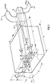
- fuel inlet means 11 and oxidant inlet means 13 may comprise a fuel inlet nozzle and oxidant inlet nozzle, as shown in Fig. 1, or may comprise any other suitable inlet means for introducing fuel and oxidant into corresponding manifolds, as known to those skilled in the art
- the term fuel is intended to interchangeably relate to any suitable gaseous fuel, vaporized liquid fuel, liquefied gas, or any other fuel suitable for combustion purposes.
- One preferred fuel is natural gas.
- the term oxidant is intended to interchangeably relate to oxygen, air, oxygen-enriched air, or any other suitable oxidant known to those skilled in the art.
- One preferred oxidant used in connection with the method according to this invention is pure or 100% oxygen. The combination of pure or 100% oxygen and natural gas is often used in high-temperature furnaces, such as glass melting furnaces.
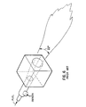
- the apparatus for injecting the fuel and the oxidant into a combustion burner comprises fuel discharge nozzle 15 and oxidant discharge nozzle 25.
- Fuel means are used to discharge the fuel from a fuel exit plane generally defined by fuel discharge nozzle 15, preferably in a generally planar fuel layer which has a generally planar upper boundary and a generally planar lower boundary.
- First oxidant means are used to discharge a first portion of the oxidant from an oxidant exit plane generally defined by oxidant discharge nozzle 25, preferably in a generally planar first oxidant layer, preferably along the upper boundary of the fuel layer.
- Second oxidant means are used to discharge a second or remaining portion of the oxidant from the oxidant exit plane at oxidant discharge nozzle 25, also in a generally planar second oxidant layer, preferably along the lower boundary of the fuel layer.
- the phrase generally planar layer is intended to relate to a fluidic layer of gas or vaporized fuel, for example, having a defined layer thickness and an overall generally planar shape. Such generally planar layer may also be referred to as a blanket of gas or vaporized liquid.
- the generally planar layer of fuel and oxidant are formed within fuel discharge nozzle 15 and oxidant discharge nozzle 25, respectively. Upstream of the generally vertical exit planes, one at fuel discharge nozzle 15 and another at oxidant discharge nozzle 25, the fuel and oxidant are correspondingly formed into separate generally planar layers. Downstream of the exit planes, the generally planar layers of fuel and oxidant begin to commingle at their common boundaries and continue to mix as the flow proceeds in the downstream direction.
- the generally planar fuel layer is sandwiched between the first oxidant layer and the second oxidant layer.
- the oxidant begins to mix with the fuel to create a fuel-rich phase layer of a fuel/oxidant mixture which is sandwiched between two oxygen-rich phase layers of the fuel/oxidant mixture.
- the peak flame temperatures of combustion occurring shortly downstream of fuel discharge nozzle 15 and oxidant discharge nozzle 25 are extremely low. Such relatively low peak flame temperatures result in reduced undesirable emissions.
- convective cooling of refractory manifold 47 occurs.
- the fuel means used to discharge the fuel from fuel discharge nozzle 15 comprise fuel manifold 17 having a generally rectangular cross section at a downstream portion of fuel manifold 17.
- fuel manifold 17 has a generally square cross section at an upstream portion. As fuel manifold 17 extends into the downstream portion, the cross section becomes much more rectangular, with a long side of the rectangle preferably positioned in a generally horizontal direction. It is apparent that the upstream portion can have any suitably shaped cross section, including a circular cross section, as long as the upstream section transitions into a generally rectangular cross section at the downstream portion.
- the fishtail or fan-shaped flame configuration has the flat portion of the flame generally oriented in the horizontal direction, which is preferred. However, it is apparent that such flat portion can be oriented at any other suitable angle, which would accomplish the same result of producing a fishtail or fan-shaped flame with a fuel-rich layer sandwiched between two oxidant-rich layers. With the flat portion oriented at another suitable angle, the generally horizontal direction would not be with respect to gravitational forces.
- upper wall 18 and lower wall 20 converge with respect to each other, and opposing side walls 22 diverge with respect to each other, in the downstream direction.
- upper wall 28 and lower wall 30 converge with respect to each other and opposing side walls 32 diverge with respect to each other, in the downstream direction.
- fuel manifold 17 is positioned within oxidant manifold 27, as clearly shown in Fig. 1. A major portion of fuel manifold 17 is shown in dashed or hidden lines in Fig. 1, since fuel manifold 17 is positioned within oxidant manifold 27.
- an oxidant flow channel is defined between upper wall 18 and upper wall 28, between lower wall 20 and lower wall 30, and preferably but not necessarily also between opposing side walls 22 and respective opposing side walls 32.
- the oxidant flowing between corresponding side flow surfaces 23 and 33 also sandwiches the fuel layer, in a side-to-side manner.
- convergence angle ⁇ is the angle at which opposing side flow surfaces 23 converge, and preferably but not necessarily the angle at which opposing side flow surfaces 33 converge.
- Divergence angle ⁇ is the angle at which upper flow surface 19 and lower flow surface 21 diverge, and preferably but not necessarily the angle at which upper flow surface 29 and lower flow surface 31 diverge.
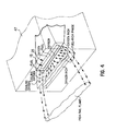
- Divergence angle ⁇ is the included angle at which the flame diverges, as measured from the centerline direction of refractory manifold 47.
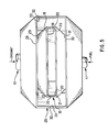
- divergent means 40 comprise refractory manifold 47 having a generally rectangular cross section.
- Upper flow surface 49 of upper wall 48 and lower flow surface 51 of lower wall 50 preferably diverge in the downstream flow direction. The distance between upper flow surface 49 and lower flow surface 51 is preferably but not necessarily maintained constant.
- Fig. 1 shows various dimensions which may be critical to the apparatus of this invention, depending upon the particular use of the burner.
- the method and apparatus of this invention were experimentally tested and preferred ranges of such dimensions are discussed below, as well as the effect upon the burner performance by varying such dimensions.
- the following ranges of dimensions, angles and velocities are those which are preferred based upon experiments conducted with the method and apparatus of this invention.
- further experimentation could reveal other suitable dimensions, angles, ratios and velocities outside of the preferred ranges.
- the dimensions, angles, ratios and velocities discussed below are examples and are specifically intended to not limit the scope of this invention.
- Convergence angle ⁇ is measured within a generally vertical plane. According to one preferred embodiment of this invention, convergence angle ⁇ is approximately 3° to approximately 8°. Convergence angle ⁇ represents the angle at which side flow surfaces 23 and side flow surfaces 33 converge with respect to the horizontal. A properly selected convergence angle ⁇ allows the respective flow surface to adequately squeeze or pinch the fuel or oxidant streamlines in the flow axis, so that the fuel or oxidant flow converges at a somewhat steady rate without undue turbulence.
- the transfer of fluidic momentum of the fuel or oxidant, from the vertical plane to the horizontal plane, is a function of convergence angle ⁇ , as well as divergence angle ⁇ . A proper balance between the design of convergence angle ⁇ and divergence angle ⁇ is required for adequately converging and simultaneously diverging the flow streamlines of both the fuel and the oxidant.
- Divergence angle ⁇ is preferably in a range of approximately 6° to approximately 12°. Divergence angle ⁇ is measured in a generally horizontal plane and dictates the degree to which upper flow surface 19, lower flow surface 21, upper flow surface 29 and lower flow surface 31 diverge in the generally horizontal direction. Because of divergence angle ⁇ , the fluidic fuel stream and the fluidic oxidant stream each expand while each such fluid is simultaneously forced to converge within their respective manifold, due to convergence angle ⁇ . When divergence angle ⁇ is too large, empty fluidic pockets can form near sidewalls 22 and sidewalls 32 of fluid discharge nozzle 15 and oxidant discharge nozzle 25, respectively.
- divergence angle ⁇ When divergence angle ⁇ is too small, relatively heavy fluid distribution can occur closer to the center of fuel discharge nozzle 15 or oxidant discharge nozzle 25 A proper combination of both convergence angle ⁇ and divergence angle ⁇ will result in uniformly distributed fuel and oxidant streams across the exit cross section of fuel discharge nozzle 15 and oxidant discharge nozzle 25, which will ultimately result in uniform flame development and uniform cooling of refractory manifold 47.
- the ratio L c /W, the convergence length L c to the divergence width W of oxidant discharge nozzle 25, is preferably in a range of approximately 1 to approximately 3.
- the ratio L c /W is heavily based upon the values of convergence angle ⁇ and divergence angle ⁇ .
- the ratio L c /W is also based upon the firing capacity of the burner. For relatively higher firing rates the ratio L c /W is a larger number, and for relatively lower firing rates the ratio L c /W is a smaller number.
- the ratio W/D, the width W to the depth D of oxidant discharge nozzle 25, is preferably in a range of approximately 3 to approximately 6.
- a relatively higher ratio W/D tends to spread the oxidant in the horizontal plane, whereas a relatively lower ratio W/D tends to increase the thickness of the oxidant layer in the generally vertical plane, at given values for the oxidant velocity, the firing rate, convergence angle ⁇ and divergence angle ⁇ .
- the oxidant velocity depending upon the burner firing rate, is preferably in a range from approximately 5 to approximately 100 ft/sec.
- the ratio w/d which is a ratio of the width w to the depth d of fuel discharge nozzle 15, is preferably in a range of approximately 15 to approximately 25.
- a relatively higher ratio w/d tends to spread the fuel in the horizontal plane, whereas a relatively lower ratio w/d tends to increase the thickness of the fuel layer, when measured in the vertical plane.
- the ratio w/d is selected depending upon the desired fuel velocity discharged from fuel discharge nozzle 15, at given values for the firing rate, convergence angle ⁇ and divergence angle ⁇ .
- a preferred range of fuel velocities depending upon the burner firing rate, is from approximately 5 to approximately 150 ft/sec.
- Flame divergence angle ⁇ which is measured in the generally horizontal plane, from the centerline axis of refractory manifold 47 as shown in Fig. 1, is preferably in a range from approximately 10° to approximately 40°. Flame divergence angle ⁇ depends upon the design of refractory manifold 47. The divergence of the flame discharged from refractory manifold 47 is influenced by flame divergence angle ⁇ . A relatively lower flame divergence angle ⁇ intensifies the combustion process and a relatively higher flame divergence angle ⁇ reduces the overall cooling effect of the oxidant on the flow surfaces of refractory manifold 47.
- a properly selected flame divergence angle ⁇ will result in optimum divergence of the flame due to combustion induced expansion of relatively hot combustion gases, for greater load coverage.
- a properly selected flame divergence angle ⁇ will also assist in stabilizing the combustion process within refractory manifold 47, or another suitable burner block, and thus will optimize the cooling effect upon refractory manifold 47.
- a properly selected flame divergence angle ⁇ will also result in refractory manifold 47 being completely filled with relatively hot combustion gases, which also prevents inspiration of furnace gases or particulates into refractory manifold 47, or another suitable burner block.
- the ratio L/D which is a ratio of the flow length L to the flow depth D of refractory manifold 47, is preferably in a range of approximately 1.5 to approximately 2.5.
- the ratio L/D influences the flame luminosity, as well as the cooling effect caused by the oxidant flow over upper flow surface 49 of upper wall 48, lower flow surface 51 of lower wall 50 and side flow surfaces 53 of sidewalls 52.
- a relatively higher ratio L/D tends to accelerate the fuel/oxidant combustion process and thus reduce the thickness of the oxidant layers which sandwich the fuel layer.
- an oxidant layer thickness of approximately 3/8" to approximately 3/4" is preferred for adequate cooling of refractory manifold 47.
- a properly selected L/D ratio will result in good flame luminosity and partial fuel cracking within the central fuel layer.
- the L/D ratio is increased, such as beyond approximately 2.5, the combustion process can become more intense within refractory manifold 47, the generation of soot species can be significantly reduced, and the flame luminosity can also be reduced.
- the L/D ratio such as lower than approximately 1.5, the residence time for the hot gases to expand and shape the flame becomes too short.
- the velocities of the fuel and oxidant at the nozzle exit planes become important design parameters when the combustion burner operates with pure or 100% oxygen and fuel. Relatively higher velocities can be achieved by using smaller nozzle exit areas and would likely result in reduced flame luminosity.
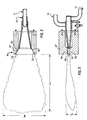
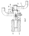
- fuel manifold 117 can be adjustably moved in a longitudinal direction in order to adjustably vary the position of fuel exit plane 116 with respect to oxidant exit plane 126.
- fuel manifold 117 is positioned with respect to oxidant manifold 127 such that fuel exit plane 116 is in an upstream position with respect to oxidant exit plane 126.
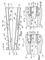
- the position of fuel manifold 117 with respect to oxidant manifold 127 can be adjusted in the longitudinal direction so that fuel exit plane 116 is downstream with respect to oxidant exit plane 126, as shown in Fig. 10.
- the arrow in each of Figs. 9 and 10 represents both the general longitudinal direction and the downstream direction of fluid flow through fuel manifold 117 and oxidant manifold 127.
- oxidant manifold 127 is secured with respect to refractory manifold 147.
- a forward portion of fuel manifold 117 is mounted within oxidant manifold 127.
- O-ring 167 is used to hermetically seal the connection between fuel manifold 117 and oxidant manifold 127. It is apparent that a gasket or other suitable sealing device known to those skilled in the art can be used in addition to or in lieu of O-ring 167.
- Fig. 8 shows a partial cross-sectional partial side view of the forward portion of fuel manifold 117, as mounted within oxidant manifold 127.
- oxidant manifold 127 preferably remains secured with respect to refractory manifold 147 and fuel manifold 117 preferably moves in a general longitudinal direction, such as along the arrow shown in Fig. 8, it is apparent that other mechanical arrangements can be used to accomplish the same relative movement.
- the position of fuel manifold 117 can be fixed with respect to refractory manifold 147 and oxidant manifold 127 can be adjustably moved with respect to fuel manifold 117.
- adjustment means 160 are used to adjustably move and fix fuel manifold 117 with respect to oxidant manifold 127.
- adjustment means 160 comprise bracket 162 fixed with respect to oxidant manifold 127 and bracket 164 fixed with respect to fuel manifold 117.
- Screw 166 is threadedly engaged within corresponding internally threaded holes within bracket 162 and bracket 164. By rotating screw 166 bracket 164 moves with respect to bracket 162 and thus fuel manifold 117 moves with respect to oxidant manifold 127.
- Sight gauge 165 can be secured to either bracket 162 or bracket 164, for example, to indicate the position of fuel manifold 117 relative to oxidant manifold 127 and thus the position of fuel exit plane 116 relative to oxidant exit plane 126. It is apparent that other suitable mechanical devices known to those skilled in the art can be used to adjustably move and fix the position of fuel manifold 117 with respect to oxidant manifold 127.
- pin 168 has a slot, identified by dashed lines, into which guideplate 170 slidably engages.
- Pin 168 acts as a guide for maintaining the longitudinal sliding direction of fuel manifold 117 with respect to oxidant manifold 127.
- pin 168 is fixed in a suitable manner, such as being welded or the like, with respect to oxidant manifold 127. It is apparent that other mechanical devices known to those skilled in the art can be used to guide longitudinal movement of fuel manifold 117 with respect to oxidant manifold 127. It is also apparent that the roles can be reversed by securing pin 168 with respect to fuel manifold 117 and securing guideplate 170 with respect to oxidant manifold 127.
- fuel exit plane 116 is positioned upstream with respect to oxidant exit plane 126. As shown in Fig. 10, fuel exit plane 116 is positioned downstream with respect to oxidant exit plane 126.
- the arrows indicate the general direction of fluid flow.
- the peak flame temperature can be variably positioned along the longitudinal axis of the flame. Adjusting the flame shape can also result in different heat-release patterns and overall heat-transfer rates that the flame offers to its surroundings. A properly adjusted flame can significantly improve fuel efficiency and furnace overall productivity.
- fuel exit plane 116 is positioned upstream with respect to oxidant exit plane 126.
- the distance between fuel exit plane 116 and oxidant exit plane 126 can vary as a function of the furnace and/or flame requirements, according to one preferred embodiment of this invention, such distance is about 0.5".
- fuel exit plane 116 is positioned downstream with respect to oxidant exit plane 126. Although such distance can also vary depending upon the flame and/or furnace requirements, according to one preferred embodiment of this invention, such distance can be as much as about 1".
- the oxidant velocity varies as fuel manifold 117 is moved with respect to oxidant manifold 127, because of the change in cross-sectional area of the oxidant flow path.
- moving fuel exit plane 116 between extreme upstream and downstream positions results in only a difference of about 10%-15% in oxidant flow velocities.
- the cross-sectional area of the fuel path remains constant the velocity of fuel within fuel manifold 117 remains approximately constant as fuel manifold 117 is moved between extreme upstream and downstream positions.
Landscapes
- Engineering & Computer Science (AREA)
- Chemical & Material Sciences (AREA)
- Combustion & Propulsion (AREA)
- Mechanical Engineering (AREA)
- General Engineering & Computer Science (AREA)
- Gas Burners (AREA)
- Pre-Mixing And Non-Premixing Gas Burner (AREA)
Claims (7)
- Vorrichtung zum Feinverteilen von Brennstoff und Oxidationsmittel von einem Brenner in eine Brennkammer, mit einer inneren Düse (15,115) zum Feinverteilen des Brennstoffes, die im wesentlichen plane obere und untere Wände (18,118; 20,120) sowie in Bezug aufeinander divergierende Seitenwände hat, sowie eine äussere Düse (25,125), die distanziert um die innere Düse verläuft, zur Feinverteilung des Oxidationsmittels dient und in Bezug aufeinander divergierende Seitenwände (32) hat und mit oberen und unteren Wänden (28,128;30,130) einen im wesentlichen rechteckigen Auslass bildet, dadurch gekennzeichnet, dass die oberen (18,118) und unteren Wände (20,120) der inneren Düse (15) in Bezug zueinander konvergieren und die oberen (28,128) und unteren Wände (30,130) der äusseren Düse (25) in Bezug aufeinander zusammenlaufend sind.
- Vorrichtung nach Anspruch 1, dadurch gekennzeichnet, dass eine Brennstoffauslassebene (116), die durch die Enden der oberen, unteren und seitlichen Wände (118,120,123) der inneren Düse definiert ist, und eine Oxidationsmittelaustrittsebene (126), die durch die Enden der oberen, unteren und seitlichen Wände (128,130,133) der äusseren Düse definiert ist, so relativ zueinander angeordnet sind, dass sie durch Längsverschiebemittel (160) relativ zueinander verschieblich distanziert fixierbar sind.
- Vorrichtung nach Anspruch 2, dadurch gekennzeichnet, dass die Brennstoffauslassebene (116) in eine, bezogen auf die Strömungsrichtung durch den Brenner, stromaufwärts gelegene Stellung relativ zur Oxidationsmittelaustrittsebene (126) verschiebbar ist.
- Vorrichtung nach Anspruch 2, dadurch gekennzeichnet, dass die Brennstoffauslassebene (116) in eine, bezogen auf die Strömungsrichtung durch den Brenner, stromabwärts gelegene Stellung relativ zur Oxidationsmittelaustrittsebene (126) verschiebbar ist.
- Vorrichtung nach Anspruch 2, dadurch gekennzeichnet, dass das Längsverschiebemittel (160) eine erste mit der inneren Düse (115) verbundene Tragkonsole (164) und eine zweite mit der äusseren Düse (125) verbundene Tragkonsole (162) umfasst, wobei die erste Konsole ein erstes Gewindeloch und die zweite Konsole ein zweites Gewindeloch hat und eine Schraube (166) mit Aussengewinde die beiden Löcher mit Innengewinde passend durchsetzt.
- Vorrichtung nach Anspruch 2, dadurch gekennzeichnet, dass das Längsverschiebemittel (160) einen mit der äusseren Düse (125) verbundenen Stift (168) mit einem Schlitz umfasst, in dem eine mit der inneren Düse (115) verbundene Führungsplatte (170) gleitend gehalten ist.
- Vorrichtung nach Anspruch 2, dadurch gekennzeichnet, dass das Längsverschiebemittel (160) einen mit der inneren Düse (115) verbundenen Stift (168) mit einem Schlitz umfasst, in dem eine mit der äusseren Düse (125) verbundene Führungsplatte (170) gleitend gehalten ist.
Applications Claiming Priority (3)
| Application Number | Priority Date | Filing Date | Title |
|---|---|---|---|
| US08/366,621 US5545031A (en) | 1994-12-30 | 1994-12-30 | Method and apparatus for injecting fuel and oxidant into a combustion burner |
| US366621 | 1994-12-30 | ||
| PCT/US1995/017069 WO1996021823A2 (en) | 1994-12-30 | 1995-12-29 | Method and apparatus for dispensing fuel and oxidant from a burner |
Publications (2)
| Publication Number | Publication Date |
|---|---|
| EP0800636A1 EP0800636A1 (de) | 1997-10-15 |
| EP0800636B1 true EP0800636B1 (de) | 2000-12-06 |
Family
ID=23443789
Family Applications (1)
| Application Number | Title | Priority Date | Filing Date |
|---|---|---|---|
| EP95944768A Expired - Lifetime EP0800636B1 (de) | 1994-12-30 | 1995-12-29 | Vorrichtung zum austrag von brennstoff und oxidationsmittel aus einem brenner |
Country Status (6)
| Country | Link |
|---|---|
| US (1) | US5545031A (de) |
| EP (1) | EP0800636B1 (de) |
| AU (1) | AU5019396A (de) |
| BR (1) | BR9510127A (de) |
| DE (1) | DE69519592D1 (de) |
| WO (1) | WO1996021823A2 (de) |
Families Citing this family (70)
| Publication number | Priority date | Publication date | Assignee | Title |
|---|---|---|---|---|
| US5725367A (en) * | 1994-12-30 | 1998-03-10 | Combustion Tec, Inc. | Method and apparatus for dispersing fuel and oxidant from a burner |
| FR2771798B1 (fr) * | 1997-12-02 | 1999-12-31 | Air Liquide | Bruleur oxy-combustible |
| FR2784449B1 (fr) * | 1998-10-13 | 2000-12-29 | Stein Heurtey | Bruleur a combustible fluide notamment pour fours de rechauffage de produits siderurgiques |
| US6394792B1 (en) | 1999-03-11 | 2002-05-28 | Zeeco, Inc. | Low NoX burner apparatus |
| US5980243A (en) * | 1999-03-12 | 1999-11-09 | Zeeco, Inc. | Flat flame |
| US6244854B1 (en) * | 1999-05-13 | 2001-06-12 | The Boc Group, Inc. | Burner and combustion method for the production of flame jet sheets in industrial furnaces |
| US6579085B1 (en) * | 2000-05-05 | 2003-06-17 | The Boc Group, Inc. | Burner and combustion method for the production of flame jet sheets in industrial furnaces |
| US6659762B2 (en) | 2001-09-17 | 2003-12-09 | L'air Liquide - Societe Anonyme A' Directoire Et Conseil De Surveillance Pour L'etude Et L'exploitation Des Procedes Georges Claude | Oxygen-fuel burner with adjustable flame characteristics |
| FR2853959B1 (fr) * | 2003-04-18 | 2005-06-24 | Stein Heurtey | Procede de controle de l'homogeneite de temperature des produits dans un four de rechauffage de siderurgie, et four de rechauffage |
| US6939130B2 (en) * | 2003-12-05 | 2005-09-06 | Gas Technology Institute | High-heat transfer low-NOx combustion system |
| US7390189B2 (en) | 2004-08-16 | 2008-06-24 | Air Products And Chemicals, Inc. | Burner and method for combusting fuels |
| FR2892497B1 (fr) * | 2005-10-24 | 2008-07-04 | Air Liquide | Procede de combustion mixte dans un four a regenerateurs |
| US7802452B2 (en) | 2005-12-21 | 2010-09-28 | Johns Manville | Processes for making inorganic fibers |
| US7581948B2 (en) * | 2005-12-21 | 2009-09-01 | Johns Manville | Burner apparatus and methods for making inorganic fibers |
| EP2068077A4 (de) * | 2006-09-27 | 2016-10-12 | Mitsubishi Hitachi Power Sys | Brenner und den brenner enthaltende(r) verbrennungseinrichtung und kessel |
| US9651253B2 (en) * | 2007-05-15 | 2017-05-16 | Doosan Power Systems Americas, Llc | Combustion apparatus |
| US9353945B2 (en) * | 2008-09-11 | 2016-05-31 | Jupiter Oxygen Corporation | Oxy-fuel combustion system with closed loop flame temperature control |
| MX2011006820A (es) * | 2009-01-16 | 2011-07-12 | Air Prod & Chem | Dispositivo de combustion multimodal y metodo para utilizar el dispositivo. |
| GB0904948D0 (en) * | 2009-03-23 | 2009-05-06 | Monitor Coatings Ltd | Compact HVOF system |
| US9221704B2 (en) * | 2009-06-08 | 2015-12-29 | Air Products And Chemicals, Inc. | Through-port oxy-fuel burner |
| US8875544B2 (en) | 2011-10-07 | 2014-11-04 | Johns Manville | Burner apparatus, submerged combustion melters including the burner, and methods of use |
| US9776903B2 (en) | 2010-06-17 | 2017-10-03 | Johns Manville | Apparatus, systems and methods for processing molten glass |
| US9021838B2 (en) | 2010-06-17 | 2015-05-05 | Johns Manville | Systems and methods for glass manufacturing |
| US9032760B2 (en) | 2012-07-03 | 2015-05-19 | Johns Manville | Process of using a submerged combustion melter to produce hollow glass fiber or solid glass fiber having entrained bubbles, and burners and systems to make such fibers |
| US8650914B2 (en) | 2010-09-23 | 2014-02-18 | Johns Manville | Methods and apparatus for recycling glass products using submerged combustion |
| US8973400B2 (en) | 2010-06-17 | 2015-03-10 | Johns Manville | Methods of using a submerged combustion melter to produce glass products |
| US10322960B2 (en) | 2010-06-17 | 2019-06-18 | Johns Manville | Controlling foam in apparatus downstream of a melter by adjustment of alkali oxide content in the melter |
| US9096452B2 (en) | 2010-06-17 | 2015-08-04 | Johns Manville | Methods and systems for destabilizing foam in equipment downstream of a submerged combustion melter |
| US8769992B2 (en) | 2010-06-17 | 2014-07-08 | Johns Manville | Panel-cooled submerged combustion melter geometry and methods of making molten glass |
| US8707740B2 (en) | 2011-10-07 | 2014-04-29 | Johns Manville | Submerged combustion glass manufacturing systems and methods |
| US8707739B2 (en) | 2012-06-11 | 2014-04-29 | Johns Manville | Apparatus, systems and methods for conditioning molten glass |
| US8997525B2 (en) | 2010-06-17 | 2015-04-07 | Johns Manville | Systems and methods for making foamed glass using submerged combustion |
| US8991215B2 (en) | 2010-06-17 | 2015-03-31 | Johns Manville | Methods and systems for controlling bubble size and bubble decay rate in foamed glass produced by a submerged combustion melter |
| US8973405B2 (en) | 2010-06-17 | 2015-03-10 | Johns Manville | Apparatus, systems and methods for reducing foaming downstream of a submerged combustion melter producing molten glass |
| US9534510B2 (en) | 2011-03-07 | 2017-01-03 | Dynamis Energy, Llc | System and method for thermal chemical conversion of waste |
| CA2827865C (en) * | 2011-03-10 | 2016-01-05 | Air Products And Chemicals, Inc. | Oxy-fuel burner arrangement |
| PL2812633T3 (pl) * | 2011-12-01 | 2019-06-28 | Air Products And Chemicals, Inc. | Palniki o szybkim uwalnianiu energii i sposoby ich stosowania |
| US9533905B2 (en) | 2012-10-03 | 2017-01-03 | Johns Manville | Submerged combustion melters having an extended treatment zone and methods of producing molten glass |
| US9316411B2 (en) | 2012-07-20 | 2016-04-19 | Trane International Inc. | HVAC furnace |
| WO2014055199A1 (en) | 2012-10-03 | 2014-04-10 | Johns Manville | Methods and systems for destabilizing foam in equipment downstream of a submerged combustion melter |
| US9227865B2 (en) | 2012-11-29 | 2016-01-05 | Johns Manville | Methods and systems for making well-fined glass using submerged combustion |
| US10654740B2 (en) | 2013-05-22 | 2020-05-19 | Johns Manville | Submerged combustion burners, melters, and methods of use |
| US10131563B2 (en) | 2013-05-22 | 2018-11-20 | Johns Manville | Submerged combustion burners |
| WO2014189506A1 (en) | 2013-05-22 | 2014-11-27 | Johns Manville | Submerged combustion burners and melters, and methods of use |
| SI2999923T1 (sl) | 2013-05-22 | 2018-11-30 | Johns Manville | Potopni zgorevalni talilnik z izboljšanim gorilnikom in ustrezen postopek |
| WO2014189499A1 (en) | 2013-05-22 | 2014-11-27 | Johns Manville | Submerged combustion burners and melters, and methods of use |
| PL3003997T3 (pl) | 2013-05-30 | 2021-11-02 | Johns Manville | Palniki do spalania pod powierzchnią cieczy ze środkami usprawniającymi mieszanie przeznaczone do pieców do topienia szkła oraz zastosowanie |
| EP3003996B1 (de) | 2013-05-30 | 2020-07-08 | Johns Manville | Tauchbrenner-glasschmelzsysteme und verfahren zu deren verwendung |
| WO2015009300A1 (en) | 2013-07-18 | 2015-01-22 | Johns Manville | Fluid cooled combustion burner and method of making said burner |
| US9593847B1 (en) | 2014-03-05 | 2017-03-14 | Zeeco, Inc. | Fuel-flexible burner apparatus and method for fired heaters |
| US9593848B2 (en) | 2014-06-09 | 2017-03-14 | Zeeco, Inc. | Non-symmetrical low NOx burner apparatus and method |
| GB201501310D0 (en) * | 2015-01-27 | 2015-03-11 | Knauf Insulation And Knauf Insulation Gmbh And Knauf Insulation Doo Skofja Loka And Knauf Insulation | Burner for submerged combustion melter |
| US9751792B2 (en) | 2015-08-12 | 2017-09-05 | Johns Manville | Post-manufacturing processes for submerged combustion burner |
| US10670261B2 (en) | 2015-08-27 | 2020-06-02 | Johns Manville | Burner panels, submerged combustion melters, and methods |
| US10041666B2 (en) | 2015-08-27 | 2018-08-07 | Johns Manville | Burner panels including dry-tip burners, submerged combustion melters, and methods |
| US9815726B2 (en) | 2015-09-03 | 2017-11-14 | Johns Manville | Apparatus, systems, and methods for pre-heating feedstock to a melter using melter exhaust |
| US9982884B2 (en) | 2015-09-15 | 2018-05-29 | Johns Manville | Methods of melting feedstock using a submerged combustion melter |
| US10837705B2 (en) | 2015-09-16 | 2020-11-17 | Johns Manville | Change-out system for submerged combustion melting burner |
| US10081563B2 (en) | 2015-09-23 | 2018-09-25 | Johns Manville | Systems and methods for mechanically binding loose scrap |
| US10144666B2 (en) | 2015-10-20 | 2018-12-04 | Johns Manville | Processing organics and inorganics in a submerged combustion melter |
| US10246362B2 (en) | 2016-06-22 | 2019-04-02 | Johns Manville | Effective discharge of exhaust from submerged combustion melters and methods |
| CN106277718B (zh) * | 2016-08-19 | 2019-03-15 | 巨石集团有限公司 | 一种玻璃纤维池窑用玻璃液通道加热方法 |
| US10301208B2 (en) | 2016-08-25 | 2019-05-28 | Johns Manville | Continuous flow submerged combustion melter cooling wall panels, submerged combustion melters, and methods of using same |
| US10337732B2 (en) | 2016-08-25 | 2019-07-02 | Johns Manville | Consumable tip burners, submerged combustion melters including same, and methods |
| US10196294B2 (en) | 2016-09-07 | 2019-02-05 | Johns Manville | Submerged combustion melters, wall structures or panels of same, and methods of using same |
| US10233105B2 (en) | 2016-10-14 | 2019-03-19 | Johns Manville | Submerged combustion melters and methods of feeding particulate material into such melters |
| JP7139095B2 (ja) * | 2017-02-17 | 2022-09-20 | 三菱重工業株式会社 | ボイラ |
| CN115135929A (zh) * | 2020-02-12 | 2022-09-30 | 塞拉斯热能技术有限责任公司 | 氧平焰燃烧器和块体组件 |
| CN119173340A (zh) * | 2022-03-14 | 2024-12-20 | 塞拉斯热能技术有限责任公司 | 鱼尾状火焰燃烧器组件 |
| US12516809B2 (en) * | 2022-06-30 | 2026-01-06 | Air Products And Chemicals, Inc. | Burner and method for transient heating |
Family Cites Families (15)
| Publication number | Priority date | Publication date | Assignee | Title |
|---|---|---|---|---|
| US1566177A (en) * | 1923-06-25 | 1925-12-15 | William H Whitaker | Pulverized-fuel burner |
| US2813754A (en) * | 1955-06-27 | 1957-11-19 | Zielinski Joseph | Pressure nozzles |
| GB2078364B (en) * | 1980-06-17 | 1984-02-15 | Bs & B Eng Co | Fuel inlet assemblies for fuel reactors |
| US4909727A (en) * | 1987-03-04 | 1990-03-20 | Combustion Tec, Inc. | Oxygen enriched continuous combustion in a regenerative furance |
| GB8720468D0 (en) * | 1987-08-29 | 1987-10-07 | Boc Group Plc | Flame treatment method |
| US5135387A (en) * | 1989-10-19 | 1992-08-04 | It-Mcgill Environmental Systems, Inc. | Nitrogen oxide control using internally recirculated flue gas |
| FR2656676B1 (fr) * | 1989-12-28 | 1994-07-01 | Inst Francais Du Petrole | Bruleur industriel a combustible liquide a faible emission d'oxyde d'azote, ledit bruleur generant plusieurs flammes elementaires et son utilisation. |
| FR2667928B1 (fr) * | 1990-10-16 | 1995-07-28 | Air Liquide | Procede de chauffe d'une enceinte thermique. |
| US5076779A (en) * | 1991-04-12 | 1991-12-31 | Union Carbide Industrial Gases Technology Corporation | Segregated zoning combustion |
| EP0513414B1 (de) * | 1991-05-16 | 1996-12-11 | Hotwork International S.A. | Düsenvorrichtung zur Steuerung eines Gasstromes |
| US5199866A (en) * | 1992-03-30 | 1993-04-06 | Air Products And Chemicals, Inc. | Adjustable momentum self-cooled oxy/fuel burner for heating in high temperature environments |
| US5256058A (en) * | 1992-03-30 | 1993-10-26 | Combustion Tec, Inc. | Method and apparatus for oxy-fuel heating with lowered NOx in high temperature corrosive environments |
| US5240409A (en) * | 1992-04-10 | 1993-08-31 | Institute Of Gas Technology | Premixed fuel/air burners |
| US5217363A (en) * | 1992-06-03 | 1993-06-08 | Gaz Metropolitan & Co., Ltd. And Partnership | Air-cooled oxygen gas burner assembly |
| US5299929A (en) * | 1993-02-26 | 1994-04-05 | The Boc Group, Inc. | Fuel burner apparatus and method employing divergent flow nozzle |
-
1994
- 1994-12-30 US US08/366,621 patent/US5545031A/en not_active Expired - Lifetime
-
1995
- 1995-12-29 EP EP95944768A patent/EP0800636B1/de not_active Expired - Lifetime
- 1995-12-29 AU AU50193/96A patent/AU5019396A/en not_active Abandoned
- 1995-12-29 WO PCT/US1995/017069 patent/WO1996021823A2/en not_active Ceased
- 1995-12-29 BR BR9510127A patent/BR9510127A/pt not_active Application Discontinuation
- 1995-12-29 DE DE69519592T patent/DE69519592D1/de not_active Expired - Lifetime
Also Published As
| Publication number | Publication date |
|---|---|
| EP0800636A1 (de) | 1997-10-15 |
| WO1996021823A2 (en) | 1996-07-18 |
| US5545031A (en) | 1996-08-13 |
| BR9510127A (pt) | 1997-12-30 |
| AU5019396A (en) | 1996-07-31 |
| WO1996021823A3 (en) | 1996-08-22 |
| DE69519592D1 (de) | 2001-01-11 |
Similar Documents
| Publication | Publication Date | Title |
|---|---|---|
| EP0800636B1 (de) | Vorrichtung zum austrag von brennstoff und oxidationsmittel aus einem brenner | |
| US5725367A (en) | Method and apparatus for dispersing fuel and oxidant from a burner | |
| US5823769A (en) | In-line method of burner firing and NOx emission control for glass melting | |
| US6939130B2 (en) | High-heat transfer low-NOx combustion system | |
| ES2220965T3 (es) | Proceso de combustion y aparato para el mismo con inyeccion separada de las corrientes de combustible y oxidante. | |
| CN103649640B (zh) | 氧‑燃料喷燃器组件 | |
| EP0762050B1 (de) | Brenner mit geringer NOx-Emission für stufenweise Verbrennung mit kontrollierter Abgabe von Strahlungswärme in Hochtemperaturöfen | |
| KR100408209B1 (ko) | 연료스트림및산화제스트림을분리주입하는연소방법및장치 | |
| EP0877202B1 (de) | Drallbrenner für Sauerstoff und Heizöl | |
| US5302112A (en) | Burner apparatus and method of operation thereof | |
| CN1916494B (zh) | 用于燃烧燃料的燃烧器和方法 | |
| US7896647B2 (en) | Combustion with variable oxidant low NOx burner | |
| US9285113B2 (en) | Distributed combustion process and burner | |
| WO2015123149A2 (en) | Burners with flame control and positioning, and related methods | |
| CA2276857C (en) | Wide flame burner | |
| CN111417822B (zh) | 一种能用于固体燃料和气体燃料的氧化剂-多燃料烧嘴 | |
| JP2009543012A (ja) | 炎の方向及び/又は軸角度を変更可能なバーナー並びにそれを実施する方法 | |
| JP3522506B2 (ja) | 酸素燃焼バーナと該バーナを持つ燃焼炉 | |
| US20100167219A1 (en) | Burner block for producing flat flame | |
| JPH0583808B2 (de) |
Legal Events
| Date | Code | Title | Description |
|---|---|---|---|
| PUAI | Public reference made under article 153(3) epc to a published international application that has entered the european phase |
Free format text: ORIGINAL CODE: 0009012 |
|
| 17P | Request for examination filed |
Effective date: 19970707 |
|
| AK | Designated contracting states |
Kind code of ref document: A1 Designated state(s): DE FR |
|
| GRAG | Despatch of communication of intention to grant |
Free format text: ORIGINAL CODE: EPIDOS AGRA |
|
| RTI1 | Title (correction) |
Free format text: APPARATUS FOR DISPENSING FUEL AND OXIDANT FROM A BURNER |
|
| 17Q | First examination report despatched |
Effective date: 20000321 |
|
| GRAG | Despatch of communication of intention to grant |
Free format text: ORIGINAL CODE: EPIDOS AGRA |
|
| GRAG | Despatch of communication of intention to grant |
Free format text: ORIGINAL CODE: EPIDOS AGRA |
|
| GRAH | Despatch of communication of intention to grant a patent |
Free format text: ORIGINAL CODE: EPIDOS IGRA |
|
| GRAH | Despatch of communication of intention to grant a patent |
Free format text: ORIGINAL CODE: EPIDOS IGRA |
|
| GRAA | (expected) grant |
Free format text: ORIGINAL CODE: 0009210 |
|
| AK | Designated contracting states |
Kind code of ref document: B1 Designated state(s): DE FR |
|
| PG25 | Lapsed in a contracting state [announced via postgrant information from national office to epo] |
Ref country code: FR Free format text: LAPSE BECAUSE OF FAILURE TO SUBMIT A TRANSLATION OF THE DESCRIPTION OR TO PAY THE FEE WITHIN THE PRESCRIBED TIME-LIMIT Effective date: 20001206 |
|
| REF | Corresponds to: |
Ref document number: 69519592 Country of ref document: DE Date of ref document: 20010111 |
|
| PG25 | Lapsed in a contracting state [announced via postgrant information from national office to epo] |
Ref country code: DE Free format text: LAPSE BECAUSE OF FAILURE TO SUBMIT A TRANSLATION OF THE DESCRIPTION OR TO PAY THE FEE WITHIN THE PRESCRIBED TIME-LIMIT Effective date: 20010307 |
|
| EN | Fr: translation not filed | ||
| PLBE | No opposition filed within time limit |
Free format text: ORIGINAL CODE: 0009261 |
|
| STAA | Information on the status of an ep patent application or granted ep patent |
Free format text: STATUS: NO OPPOSITION FILED WITHIN TIME LIMIT |
|
| 26N | No opposition filed |