EP0800634B1 - A joint device for a lubrication system and a pump apparatus including the joint device - Google Patents
A joint device for a lubrication system and a pump apparatus including the joint device Download PDFInfo
- Publication number
- EP0800634B1 EP0800634B1 EP95942363A EP95942363A EP0800634B1 EP 0800634 B1 EP0800634 B1 EP 0800634B1 EP 95942363 A EP95942363 A EP 95942363A EP 95942363 A EP95942363 A EP 95942363A EP 0800634 B1 EP0800634 B1 EP 0800634B1
- Authority
- EP
- European Patent Office
- Prior art keywords
- joint device
- lubricant
- container
- oil
- pump
- Prior art date
- Legal status (The legal status is an assumption and is not a legal conclusion. Google has not performed a legal analysis and makes no representation as to the accuracy of the status listed.)
- Expired - Lifetime
Links
Images


Classifications
-
- F—MECHANICAL ENGINEERING; LIGHTING; HEATING; WEAPONS; BLASTING
- F16—ENGINEERING ELEMENTS AND UNITS; GENERAL MEASURES FOR PRODUCING AND MAINTAINING EFFECTIVE FUNCTIONING OF MACHINES OR INSTALLATIONS; THERMAL INSULATION IN GENERAL
- F16N—LUBRICATING
- F16N7/00—Arrangements for supplying oil or unspecified lubricant from a stationary reservoir or the equivalent in or on the machine or member to be lubricated
- F16N7/30—Arrangements for supplying oil or unspecified lubricant from a stationary reservoir or the equivalent in or on the machine or member to be lubricated the oil being fed or carried along by another fluid
-
- F—MECHANICAL ENGINEERING; LIGHTING; HEATING; WEAPONS; BLASTING
- F16—ENGINEERING ELEMENTS AND UNITS; GENERAL MEASURES FOR PRODUCING AND MAINTAINING EFFECTIVE FUNCTIONING OF MACHINES OR INSTALLATIONS; THERMAL INSULATION IN GENERAL
- F16N—LUBRICATING
- F16N39/00—Arrangements for conditioning of lubricants in the lubricating system
- F16N39/002—Arrangements for conditioning of lubricants in the lubricating system by deaeration
Definitions
- the present invention relates to a joint device for a lubricating system, which is intended to be insertable in a container with lubricant, and which comprises an outlet conduit for the removal of lubricant from the container and an inlet part for the supply of lubricant of the container.
- the invention relates to a pump apparatus, preferably for producing a subpressure in a milking machine, comprising a pump, having a suction side arid a pressure side, and a lubrication device for lubricating the pump.
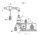
- the pump device comprises a vacuum pump 1 having a suction side 2 and a pressure side 3 terminating in an outlet tube 4.
- a so called lubricator 5 is used, which comprises an oil container 6 and in its lower part an oil distributor, not shown. With the aid of the oil distributor, it is possible to guide the oil flow to the bearings via oil conduits 7.
- On the pressure side 3 of the vacuum pump is provided a silencer 8 and an oil trap 9. Both of them separate oil, which is carried by the air on the pressure side, to a respective container 6a and 6b.
- This known pump device leads to the following problems.
- the container 6 provided on the lubricator 5 has to be filled with new oil before it is empty, in order to avoid that the bearings jam. Therefore, continuous supervision of the oil level in the container is necessary.
- the oil containers 6a and 6b, which are connected to the oil trap 9 and the silencer 8 and which collect the oil separated, also have to be continuously supervised in order to avoid that oil flows out on the floor.
- the oil flow through the lubricator 5 is controlled by means of a valve directly influencing the oil flow by throttling or opening a passage through which the oil is flowing.
- the oil amount delivered is very difficult to regulate exactly by means of such a valve. Consequently, this adjustment is done with low accuracy today.
- the outlets are sensitive to particles of dirt or thickened accumulations of oil, which easily may stop up the outlets.
- the oil flow from the known lubricator 5 may not be observed, it is very difficult to determine how much oil that has been delivered.
- the oil consumption increases drastically if for example any one of the shaft bearings of the vacuum pump is leaking. Since this increase may not be observed, such a leakage may lead to the breakdown of the bearings.
- the function of the lubricator 5 is very sensitive to a small inclination of the lubricator, since this results in an unequal distribution of oil to the different oil conduits 7, and thus to the different bearings of the pump.
- the lubricator 5 demonstrates an open construction, which gives rise to a risk for accumulation of dirt in the oil. Consequently, the bearings may be supplied with impurities.
- DE-A-3 711 000 discloses an oil container for combustion engines with dry sump lubrication.
- this oil container comprises return conduit having an orifice in a conical pipe.
- the mixture of oil and air which is brought back to the oil container, may expand in the pipe and the oil is deposited on the wall of the pipe by means of a helicoidal movement.
- the oil to be transported from the container is sucked out through a separate pipe in the lower portion of the container.
- FR-A-2 559 843 discloses a device for refining of oil.
- the device comprises a container having an inlet conduit leading to a first chamber with a sloping bottom wall. Impurities are collected in a lower space and oil is sucked out via an outlet conduit from a second chamber by means of a pump.
- DE-B-2 732 474 discloses an oil suction socket for a lubricating system, which is intended to be inserted in a container with oil.
- the suction socket comprises an opening provided in the lower portion of the casing otherwise closed.
- SE-B-454 198 discloses said lubricant container to be attached to an engine. Within said lubricant container, there is provided a second smaller container which encloses an outlet conduit for the removal af lubricant from said lubricant container and an inlet conduit for the supply of lubricant to said lubricant container. The second smaller container is not intended to be inserted in said lubricant container, but is an integrated fixed part of said lubricant container.
- SE-B-454 198 does not refer to any means for separating air from the lubricant supplied to said lubricant container.
- DE-A-2 529 842 discloses lubricating system having a pump device to be immersed in a lubricant container.
- the pump device encloses an outlet means for the removal of lubricant to a machine to be lubricated, whereas the supply of lubricant to the container takes place by means of further conduit separated from the pump device.
- the object of the present invention is to overcome the problems mentioned above.
- the present invention aims at a simplified handling and reduced supervision of the lubricating system.
- the joint device initially defined, wherein the joint device comprises a casing enclosing the outlet conduit and the inlet part, and wherein the inlet part comprises a separation means for separating air from the lubricant supplied.
- the pump apparatus initially defined, wherein the lubrication device comprises a lubricant container and a joint device insertable therein, wherein the joint device comprises a casing, which encloses an outlet means for the removal of lubricant from the lubricant container and an inlet means for bringing back lubricant used to the lubricant container, and wherein the inlet means comprises a separation means for separating air from the lubricant supplied.
- all lubricant used may be brought back to a container of a type which is available on the market.
- the handling of the lubricating system is significantly facilitated; only the container need to be replaced.
- lubricant overflow which is troublesome, may be avoided, since according to the invention the container used may be appropriately located and disposed in a suitable position, i.e. turned the right way round. Due to the lubricant being circulated in the lubricating system, the risk that one runs out of lubricant, and thus that the apparatus to be lubricated is damaged, is substantially non-existent, thereby making a continuous supervision superfluous. By the separation means, it is ensured that all lubricant which has been brought back also remains in the container.
- the separation means may be disposed in an upper portion of the joint device, which may be provided such that the upper portion, and thus the separation means, under all circumstances will be located above the lubricant level. Thereby, the separation means may always operate with a maximum effect.
- the separation means comprises an expansion chamber.
- the expansion chamber may comprise a sloping wall, which positively increases the efficiency of the expansion chamber.
- the joint device By providing the joint device with an elongate shape and with a projection on the outer side of the casing, it may easily be inserted in an normal oil container.
- Fig 2 shows a pump apparatus comprising a pump 10 having a pressure side 11 and a suction side 12.
- a combined silencer and oil separator 13 in the following called the oil separator 13, from which an outlet conduit 14 is leading the sucked air out through a wall.
- the pump 10 which in this case is driven by an electric motor, is provided with two shaft bearings. In order to ensure the function of the pump 10, these bearings must continuously be supplied with lubricant.
- the pump apparatus comprises an oil container 15, which may be a usual plastic can being available on the market.
- a joint device 16 is inserted in the oil container 15. From the joint device 16 an oil conduit 17 is leading to a distribution device 18. In the distribution device 18, the incoming oil is separated, in this case, into two outlet conduits 19, conveying the oil to two bearings of the pump 10.
- the air, mixed with oil and forced out from the pump 10 on its pressure side 11, is fed to the oil separator 13. Therein, the air is conveyed in an upward and downward movement such that it may expand in an expansion chamber 20. Oil, deposited on the walls in the expansion chamber 20 and collected by filtering means 21 provided in the expansion chamber, is transported via a discharge conduit 22 from the lowest part of the oil separator 13 back to the oil container 15. Because an overpressure prevails in the oil separator 13, air and oil will be forced through the conduit 22 back to the container 15.
- the system is open, i.e. the pressure may be equalized with the atmospheric pressure at the opening of the container 15.
- the bearings of the pump 10 communicate with the suction side 12 of the pump 10, such that the pump 10 will produce a subpressure in the oil conduits 19, whereby oil will be sucked from the container 15 via the conduit 17 to the distribution device 18 and therefrom to the bearings of the pump via the conduits 19.
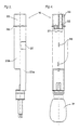
- the joint device 16 comprises an essentially cylindrical casing 23 comprising two parts 23a and 23b, for reasons of manufacture.
- the part 23a comprises a middle portion having a semi-cylindrical shape.
- An intermediate partition 24 extends between parallel outer edges of the semi-cylindrical middle portion.
- the part 23b has a semi-cylindrical shape as well and comprises an inner partition 25 dividing the room, partly enclosed by the semi-cylindrical part 23b, into two sub-rooms of essentially equal size.
- the two parts 23a, 23b of the casing are, in the example disclosed, connected to each other by hook-shaped means 26. Other types of connecting means may also be used.
- the oil conduit 17 extends through an opening 27 in the upper portion of the joint device 16, said conduit being connected to an inlet channel 28 disposed in the lower portion of the joint device 16.
- the orifice of the inlet channel 28 At the outer bottom surface of the joint device 16, there is provided the orifice of the inlet channel 28.
- the joint device 16 is provided with a cylindrical envelope surface 29 extending around the inlet channel 28 and comprising flanges 30 or similar projections for the attachment of an oil filter 31, such that the oil filter covers the orifice of the inlet channel 28.
- An inlet means 32 is provided in the upper portion of the joint device 16 and comprises a pipe socket 33 having the conduit 22 attached thereon.
- the inlet means 32 extends to a separating means 24, 34 for separation of oil from the mixture of air and oil, which is supplied via the conduit 22.
- the orifice of the inlet means 32 is disposed in an expansion chamber 34 formed by the casing 23, and more precisely by the intermediate partition 24 of the part 23a and one of the sub-rooms of the part 23b.
- the expansion chamber 34 extends downwards to a sloping wall 35, which may slope 10 - 70 degrees, preferably 20 - 50 degrees, for example about 30 degrees with respect to a horizontal plan.
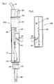
- the expansion chamber 34 extends from the sloping wall 35 back upwards on the other side of the intermediate partition 24, i.e. seen in Fig 5 the expansion chamber 34 extends upwards behind the intermediate partition 24.
- An opening 37, indicated by a dotted line in Fig 5, is provided on the other side of the intermediate partition 24 in the vertical outer wall of the part 23a.
- the mixture of air and oil conveyed through the inlet means 32 via the supply conduit 22 expands in the expansion chamber 34, such that oil is deposited on the vertical walls and the sloping wall 35 of the expansion chamber 34.
- the mixture of air and oil is subjected to a change of direction, i.e. is guided from a downward movement to an upward movement, whereby the oil being present in the air tends to continue in the first downward direction towards the sloping wall 35, due to forces of inertia and gravitation. Thereafter, the air may be removed through the opening 37 and the oil deposited is flowing downwards on the walls and through the opening 36, and back to the oil in the oil container 15.
- a flange 38 or the like is provided on the outside of the casing 23 at the upper portion of the joint device 16.
- the flange has such a shape and dimension that it may rest against the edge of the opening of the container 15 when the joint device 16 is inserted in the container 15.
- the opening of the container 15 is provided in a socket having an external thread.
- an attachment nut 39 see Fig 2, which may be threaded on the threaded socket, the joint device 16 may be fixed in the container 15.
- the joint device 16 is removably insertable in the container 15, such that it is partly immersed in the lubricant contained in the container.
- the opening of the container is provided on the top thereof, and hence the joint device is inserted by a downward movement.
- the distribution device 18 comprises an upper cylindrical portion 40 and a lower cylindrical portion 41. They are connected to each other preferably by means of a bayonet connection 42, which connects the two portions 40 and 41, and by means of a seal ring 43, seals the inner room 44 formed by the portions 41 and 42 against the atmosphere.
- the distribution device 18 comprises a longitudinal axis X-X being essentially vertical when the distribution device is in its normal operating position.
- the lower portion 41 is at least partly produced in a transparent material. At the inner bottom surface of the lower portion 41 there are provided two circular conical recesses 45.
- the upper portion 40 is on its outer side provided with an attachment means 48 by which the distribution device 18 may be fixed in its normal operation position, and on its upper side provided with a recess 49 in which an air filter 50 is disposed.
- the air may be introduced from above or through openings 51 in the envelope surface of the upper portion.
- the upper portion 40 comprises a passage 52 through which atmospheric air may be sucked from the recess 49 into the inner room 44.
- the section area of the passage 52 may be adjusted by means of an adjustment screw 53 provided in the upper portion 40.
- the upper portion 40 comprises an inlet channel 54 which by means of a pipe socket 55 is connected to the oil conduit 17 from the joint device 16 and the oil container 15.
- the inlet channel 54 has an orifice in a circular cylindrical cavity 56 which is provided on the underside of the upper portion 40 and extends coaxially with the longitudinal axis X-X.
- a distributor 57 is provided in this cavity 56.
- the distributor 57 may only be mounted in the cavity 56 with a predetermined orientation due to a pin 58 provided on a lower part of the distributor and a slot 59 provided in the cavity 56 to cooperate with the pin 58.
- the orifice of the inlet channel 54 is located opposite a peripheral surface 60 of the distributor 57, which is upwardly tapering and extends almost 180 degrees. This surface is in the example disclosed conical but may also be convex or concave, seen in a plan being parallel to the longitudinal axis X-X.
- the conical surface 60 has a central axis being coaxial with the longitudinal axis X-X and is symmetrically shaped with respect to a plan XY extending through a central axis Y-Y of the inlet channel 54 and the longitudinal axis X-X.
- the conical surface 60 is formed by a circular conical segment of the distributor 57.
- the circular conical segment changes in a downward direction to a circular cylindrical segment comprising a cylindrical envelope surface 61 abutting the wall of the circular cylindrical cavity 56.
- a circular conical segment and the circular cylindrical segment form parts of a plan surface 62 extending downwardly and parallel to the axis of the cavity 56.
- the end edges 63, 64 of the conical surface 60 define the beginning of the plan surface 62, such that an open gap 65 is formed and delimited by the plan surface 62 and another limitation which in the example disclosed, see Fig 12, is formed by a segment similarly formed with an envelope surface abutting the diametrically opposite wall of the cavity 56.
- the gap 65 extends downwardly to two sloping surfaces 66 and 67, diverging downwardly away from each other.
- the end edges 68, 69 of the surfaces 66, 67 are disposed straight above a respective outlet channel 46 when the distribution device 16 is vertically disposed.
- the oil is sucked by the subpressure from the pump 10 through the inlet channel 54 and against the conical surface 60. Since the cylindrical envelope surface 61 abuts the wall of the cavity 56 the oil may only be further transported by flowing into different directions in the flow channel formed by the conical surface 60 and the wall of the cavity 56. Hence, the flow channel will have a downwardly tapering shape, i.e. the sides of the channel are converging downwardly and are joined together at the bottom of the channel. It has now been found that due to this particular shape exactly the same amount of oil will flow in each direction independent of a slight inclination of the distribution device. When the oil arrives at the end edges 63, 64 of the conical surface 60 it will flow downwards along the plan surface 62 in two separate paths.
- the oil from one of the end edges 63 will hit the sloping surface 66 and the oil from the other end edge 64 will hit the other sloping surface 67. Due to the inclination of these surfaces 66, 67, the oil may only flow outwards and downwards and an increased separation effect of the oil paths is obtained.
- the sloping surfaces 66, 67 end straight above a respective outlet channel 46. Due to the conical recesses 45 the oil from one of the sloping surfaces 66 will therefore be transported through one of the outlet channels 46 and the oil from the upper sloping surface 67 through the other outlet channel 46, although the distribution device would incline slightly. Since the end edges 68 and 69 are disposed at a relatively long distance from the conical recess 45, the dripping frequency to the two bearings may be easily observed and adjusted by means of the adjustment screw 53.
- peripheral upwardly tapering conical surface 60, the cylindrical envelope surface 61, and the cavity 56 are all circular in the example disclosed, they may also have another shape. For example, they may be oval.
- the plan surface 62 may also comprise a non plan shape, for example a convex shape.
Landscapes
- Engineering & Computer Science (AREA)
- General Engineering & Computer Science (AREA)
- Mechanical Engineering (AREA)
- Chemical & Material Sciences (AREA)
- Combustion & Propulsion (AREA)
- Oil, Petroleum & Natural Gas (AREA)
- Compressor (AREA)
- Details And Applications Of Rotary Liquid Pumps (AREA)
- Rotary Pumps (AREA)
- Lubrication Of Internal Combustion Engines (AREA)
- Details Of Reciprocating Pumps (AREA)
- Pipeline Systems (AREA)
- Lubrication Details And Ventilation Of Internal Combustion Engines (AREA)
Description
- Fig 1
- shows a pump apparatus according to the state of the art.
- Fig 2
- shows a pump apparatus according to the invention,
- Fig 3
- shows a side view of the joint device according to the invention.
- Fig 4
- shows a partly sectional front view of the joint device in Fig 3.
- Fig 5
- shows a front view of a part of the joint device in Fig 3.
- Fig 6
- shows a front view of another part of the joint device in Fig 3.
- Fig 7
- shows a side view of a distribution device.
- Fig 8
- shows a section of the distribution device along the line VIII-VIII in Fig 7.
- Fig 9
- shows a view from above of the distribution device in Fig 7.
- Fig 10
- shows another section of the upper portion of the distribution device.
- Fig 11
- shows a side view of a distributor in the distribution device.
- Fig 12
- shows another side view of the distributor according to Fig 11.
Claims (12)
- A joint device for a lubricating system, which is intended to be insertable in a container (15) with lubricant and which comprises an outlet conduit (17), for the removal of lubricant from the container (15), and an inlet part (32, 34, 36) for the supply of lubricant to the container (15),wherein the joint device comprises a casing (23) enclosing the outlet conduit (17) and the inlet part, andwherein the inlet part comprises a separation means (24, 34, 35) for separating air from the lubricant supplied.
- A joint device according to claim 1, characterized in that it comprises an upper portion and a lower portion and that the separation means (24, 34, 35) is disposed in the upper portion.
- A joint device according to claim 2, characterized in that the separation means (24, 34, 35) comprises an expansion chamber (34).
- A joint device according to claim 3, charcterized in that the expansion chamber (34) has a lower limit comprising a sloping wall (35).
- A joint device according to claim 4, characterized in that the sloping wall (35) has a lower portion, in which an opening (36) is provided.
- A joint device according to any one of claims 3 to 5, characterized in that an opening (37) is provided in the casing (23), through which the expansion chamber (34) communicates with the environment.
- A joint device according to any one of the preceding claims, characterized in that the outlet conduit (17) comprises an outlet channel extending through the casing.
- A joint device according to claim 7, characterized in that the outlet channel communicates with the interior of the casing via a filter.
- A joint device according to claim 2 to 8, characterized in that the joint device (16) has an elongated shape and comprises on its upper portion a projection (38) provided on the outer side of the casing (23) and formed such that the joint device (16) may rest against an opening edge provided in the container, when the joint device is inserted in the container (15).
- A pump apparatus, preferably for producing a subpressure in a milking machine, comprising a pump (10), having a suction side (12) and a pressure side (11), and a lubrication device for lubricating the pump, wherein the lubrication device comprises a lubricant container (15) and a joint device insertable therein, wherein the joint device comprises a casing (23), which encloses an outlet means for the removal of lubricant from the lubricant container (15) and an inlet means for bringing back lubricant used to the lubricant container (15), and wherein the inlet means comprises a separation means (24, 34, 35) for separating air from the lubricant supplied.
- A pump apparatus according to claim 10, characterized in that a further lubricant separator (13) is provided on the pressure side of the pump (10), and that the inlet means of the joint device (16) is connected to said further lubricant separator (13) and provided to deliver lubricant separated to the lubricant container (15).
- A pump apparatus according to claim 10 or 11, characterized in that the pump (10) is connected to the lubricant container (15) via the outlet means of the joint device (16) such that an subpressure produced by the pump (10) is utilized to suck lubricant from the lubricant container (15) via the outlet means of the joint device.
Applications Claiming Priority (3)
| Application Number | Priority Date | Filing Date | Title |
|---|---|---|---|
| SE9404544 | 1994-12-28 | ||
| SE9404544A SE503941C2 (en) | 1994-12-28 | 1994-12-28 | Connection device for a lubrication system and a pump device with such a connection device |
| PCT/SE1995/001572 WO1996020367A1 (en) | 1994-12-28 | 1995-12-22 | A joint device for a lubrication system and a pump apparatus including the joint device |
Publications (2)
| Publication Number | Publication Date |
|---|---|
| EP0800634A1 EP0800634A1 (en) | 1997-10-15 |
| EP0800634B1 true EP0800634B1 (en) | 2001-11-28 |
Family
ID=20396501
Family Applications (1)
| Application Number | Title | Priority Date | Filing Date |
|---|---|---|---|
| EP95942363A Expired - Lifetime EP0800634B1 (en) | 1994-12-28 | 1995-12-22 | A joint device for a lubrication system and a pump apparatus including the joint device |
Country Status (8)
| Country | Link |
|---|---|
| US (1) | US5878841A (en) |
| EP (1) | EP0800634B1 (en) |
| JP (1) | JPH11506521A (en) |
| AU (1) | AU4361196A (en) |
| CA (1) | CA2208592A1 (en) |
| DE (1) | DE69524256T2 (en) |
| SE (1) | SE503941C2 (en) |
| WO (1) | WO1996020367A1 (en) |
Family Cites Families (13)
| Publication number | Priority date | Publication date | Assignee | Title |
|---|---|---|---|---|
| US67837A (en) * | 1867-08-20 | Improvement in bbidle-eeins | ||
| US138436A (en) * | 1873-04-29 | Improvement in lubricators | ||
| US385951A (en) * | 1888-07-10 | Alloy | ||
| US2925883A (en) * | 1957-06-25 | 1960-02-23 | Stewart Warner Corp | Lubricant aerosol generator |
| US3143188A (en) * | 1963-06-12 | 1964-08-04 | Abington Machine Company | Air line lubricator |
| DE1916967B2 (en) * | 1969-04-02 | 1976-09-16 | Daimler-Benz Ag, 7000 Stuttgart | OIL RESERVOIR FOR A ROTATIONAL PISTON COMBUSTION MACHINE |
| DE2102699A1 (en) * | 1971-01-21 | 1972-08-17 | Daimler-Benz Ag, 7000 Stuttgart | Oil tank for a rotary piston internal combustion engine with dry sump lubrication |
| SE391313B (en) * | 1974-07-08 | 1977-02-14 | Imo Industri Ab | VESSEL MACHINERY INCLUDING PART A MAIN ENGINE EQUIPPED WITH A MAIN LUBRICATE CIRCUIT WITH A MAIN LUBRICATE PUMP FOR THE PROMOTION OF LUBRICANTS TO THE MAIN ENGINE PARTS FROM A SMALL PARTS |
| DE2732474C3 (en) * | 1977-07-19 | 1980-02-14 | Bayerische Motoren Werke Ag, 8000 Muenchen | Suction basket for the suction pipe of a lubricant pump |
| FR2559843A1 (en) * | 1984-02-17 | 1985-08-23 | Amiel Serge | Device allowing a hydraulic fluid to be purified |
| SE454198B (en) * | 1986-05-13 | 1988-04-11 | Atlas Copco Ab | Lubricant Circulation System |
| DE3711000A1 (en) * | 1987-04-01 | 1988-10-20 | Porsche Ag | OILCONTAINER |
| US5004074A (en) * | 1990-01-03 | 1991-04-02 | Sundstrand Corporation | Overfill filler pipe assembly |
-
1994
- 1994-12-28 SE SE9404544A patent/SE503941C2/en not_active IP Right Cessation
-
1995
- 1995-11-22 US US08/860,134 patent/US5878841A/en not_active Expired - Fee Related
- 1995-12-22 AU AU43611/96A patent/AU4361196A/en not_active Abandoned
- 1995-12-22 WO PCT/SE1995/001572 patent/WO1996020367A1/en active IP Right Grant
- 1995-12-22 EP EP95942363A patent/EP0800634B1/en not_active Expired - Lifetime
- 1995-12-22 DE DE69524256T patent/DE69524256T2/en not_active Expired - Fee Related
- 1995-12-22 CA CA002208592A patent/CA2208592A1/en not_active Abandoned
- 1995-12-22 JP JP8520410A patent/JPH11506521A/en active Pending
Also Published As
| Publication number | Publication date |
|---|---|
| SE503941C2 (en) | 1996-10-07 |
| SE9404544D0 (en) | 1994-12-28 |
| WO1996020367A1 (en) | 1996-07-04 |
| EP0800634A1 (en) | 1997-10-15 |
| DE69524256T2 (en) | 2002-08-14 |
| DE69524256D1 (en) | 2002-01-10 |
| CA2208592A1 (en) | 1996-07-04 |
| SE9404544L (en) | 1996-06-29 |
| JPH11506521A (en) | 1999-06-08 |
| AU4361196A (en) | 1996-07-19 |
| US5878841A (en) | 1999-03-09 |
Similar Documents
| Publication | Publication Date | Title |
|---|---|---|
| CA1277501C (en) | Suction line flow stream separator for parallel compressor arrangements | |
| US6474964B2 (en) | Scroll compressor with deflector plate | |
| EP0803688B1 (en) | Accumulator | |
| EP1218676B1 (en) | A refrigerator with cyclone liquid gas separator | |
| GB2026612A (en) | Rotary positive-displacement fluid-machines | |
| JPS58144685A (en) | Compressor system | |
| EP0800634B1 (en) | A joint device for a lubrication system and a pump apparatus including the joint device | |
| US4263029A (en) | Oil reclaimer and muffler assembly and system | |
| US7096892B2 (en) | Fluid filling device | |
| US2645346A (en) | Paper machinery | |
| US5875871A (en) | Device for distribution of lubricant and a pump apparatus including the distribution device | |
| US4391573A (en) | Horizontal rotary compressor with oil forced by gas discharge into crankshaft bore | |
| JPS598672B2 (en) | Compressor for refrigerator | |
| JP2001526057A (en) | A device arranged to allow air to flow from the external environment into the internal space | |
| US5044895A (en) | Oil supply device for a rotary machine | |
| US4702089A (en) | Device for returning oil to at least one compressor in a cooling or refrigerating system | |
| US6375443B1 (en) | Screw rotor type wet vacuum pump | |
| CN107524906A (en) | Minimum quantity lubrication device | |
| CN217558973U (en) | Gear box with main shaft bearing lubricating oil channel | |
| US4034831A (en) | Oiler assembly | |
| US1702939A (en) | Lubricating system for air blowers | |
| US4838953A (en) | Adjustable oil ejector | |
| WO2003086054A1 (en) | A device for cleaning at least one teatcup | |
| US4413644A (en) | Automatic vacuum bleed valve for use on paper making machines | |
| JP2002541053A (en) | Cooling system for glassware manufacturing machines |
Legal Events
| Date | Code | Title | Description |
|---|---|---|---|
| PUAI | Public reference made under article 153(3) epc to a published international application that has entered the european phase |
Free format text: ORIGINAL CODE: 0009012 |
|
| 17P | Request for examination filed |
Effective date: 19970612 |
|
| AK | Designated contracting states |
Kind code of ref document: A1 Designated state(s): DE DK ES FR GB IT NL |
|
| RAP1 | Party data changed (applicant data changed or rights of an application transferred) |
Owner name: ALFA LAVAL AGRI AB |
|
| 17Q | First examination report despatched |
Effective date: 19990930 |
|
| GRAG | Despatch of communication of intention to grant |
Free format text: ORIGINAL CODE: EPIDOS AGRA |
|
| GRAG | Despatch of communication of intention to grant |
Free format text: ORIGINAL CODE: EPIDOS AGRA |
|
| GRAH | Despatch of communication of intention to grant a patent |
Free format text: ORIGINAL CODE: EPIDOS IGRA |
|
| GRAH | Despatch of communication of intention to grant a patent |
Free format text: ORIGINAL CODE: EPIDOS IGRA |
|
| GRAA | (expected) grant |
Free format text: ORIGINAL CODE: 0009210 |
|
| AK | Designated contracting states |
Kind code of ref document: B1 Designated state(s): DE DK ES FR GB IT NL |
|
| PG25 | Lapsed in a contracting state [announced via postgrant information from national office to epo] |
Ref country code: IT Free format text: LAPSE BECAUSE OF FAILURE TO SUBMIT A TRANSLATION OF THE DESCRIPTION OR TO PAY THE FEE WITHIN THE PRE;WARNING: LAPSES OF ITALIAN PATENTS WITH EFFECTIVE DATE BEFORE 2007 MAY HAVE OCCURRED AT ANY TIME BEFORE 2007. THE CORRECT EFFECTIVE DATE MAY BE DIFFERENT FROM THE ONE RECORDED.SCRIBED TIME-LIMIT Effective date: 20011128 |
|
| RAP2 | Party data changed (patent owner data changed or rights of a patent transferred) |
Owner name: DELAVAL HOLDING AB |
|
| REG | Reference to a national code |
Ref country code: GB Ref legal event code: IF02 |
|
| REF | Corresponds to: |
Ref document number: 69524256 Country of ref document: DE Date of ref document: 20020110 |
|
| PG25 | Lapsed in a contracting state [announced via postgrant information from national office to epo] |
Ref country code: GB Free format text: LAPSE BECAUSE OF NON-PAYMENT OF DUE FEES Effective date: 20020228 Ref country code: DK Free format text: LAPSE BECAUSE OF FAILURE TO SUBMIT A TRANSLATION OF THE DESCRIPTION OR TO PAY THE FEE WITHIN THE PRESCRIBED TIME-LIMIT Effective date: 20020228 |
|
| ET | Fr: translation filed | ||
| NLT2 | Nl: modifications (of names), taken from the european patent patent bulletin |
Owner name: DELAVAL HOLDING AB |
|
| PG25 | Lapsed in a contracting state [announced via postgrant information from national office to epo] |
Ref country code: ES Free format text: LAPSE BECAUSE OF FAILURE TO SUBMIT A TRANSLATION OF THE DESCRIPTION OR TO PAY THE FEE WITHIN THE PRESCRIBED TIME-LIMIT Effective date: 20020530 |
|
| PLBE | No opposition filed within time limit |
Free format text: ORIGINAL CODE: 0009261 |
|
| STAA | Information on the status of an ep patent application or granted ep patent |
Free format text: STATUS: NO OPPOSITION FILED WITHIN TIME LIMIT |
|
| GBPC | Gb: european patent ceased through non-payment of renewal fee |
Effective date: 20020228 |
|
| 26N | No opposition filed | ||
| PGFP | Annual fee paid to national office [announced via postgrant information from national office to epo] |
Ref country code: NL Payment date: 20081223 Year of fee payment: 14 |
|
| PGFP | Annual fee paid to national office [announced via postgrant information from national office to epo] |
Ref country code: DE Payment date: 20090202 Year of fee payment: 14 |
|
| PGFP | Annual fee paid to national office [announced via postgrant information from national office to epo] |
Ref country code: FR Payment date: 20081217 Year of fee payment: 14 |
|
| REG | Reference to a national code |
Ref country code: NL Ref legal event code: V1 Effective date: 20100701 |
|
| REG | Reference to a national code |
Ref country code: FR Ref legal event code: ST Effective date: 20100831 |
|
| PG25 | Lapsed in a contracting state [announced via postgrant information from national office to epo] |
Ref country code: NL Free format text: LAPSE BECAUSE OF NON-PAYMENT OF DUE FEES Effective date: 20100701 Ref country code: FR Free format text: LAPSE BECAUSE OF NON-PAYMENT OF DUE FEES Effective date: 20091231 |
|
| PG25 | Lapsed in a contracting state [announced via postgrant information from national office to epo] |
Ref country code: DE Free format text: LAPSE BECAUSE OF NON-PAYMENT OF DUE FEES Effective date: 20100701 |