EP0800334A2 - Circuit pour alimenter des lampes électriques - Google Patents
Circuit pour alimenter des lampes électriques Download PDFInfo
- Publication number
- EP0800334A2 EP0800334A2 EP97104698A EP97104698A EP0800334A2 EP 0800334 A2 EP0800334 A2 EP 0800334A2 EP 97104698 A EP97104698 A EP 97104698A EP 97104698 A EP97104698 A EP 97104698A EP 0800334 A2 EP0800334 A2 EP 0800334A2
- Authority
- EP
- European Patent Office
- Prior art keywords
- circuit arrangement
- circuit
- ntc
- arrangement according
- temperature sensor
- Prior art date
- Legal status (The legal status is an assumption and is not a legal conclusion. Google has not performed a legal analysis and makes no representation as to the accuracy of the status listed.)
- Granted
Links
Images
Classifications
-
- H—ELECTRICITY
- H02—GENERATION; CONVERSION OR DISTRIBUTION OF ELECTRIC POWER
- H02H—EMERGENCY PROTECTIVE CIRCUIT ARRANGEMENTS
- H02H5/00—Emergency protective circuit arrangements for automatic disconnection directly responsive to an undesired change from normal non-electric working conditions with or without subsequent reconnection
- H02H5/04—Emergency protective circuit arrangements for automatic disconnection directly responsive to an undesired change from normal non-electric working conditions with or without subsequent reconnection responsive to abnormal temperature
- H02H5/042—Emergency protective circuit arrangements for automatic disconnection directly responsive to an undesired change from normal non-electric working conditions with or without subsequent reconnection responsive to abnormal temperature using temperature dependent resistors
-
- H—ELECTRICITY
- H05—ELECTRIC TECHNIQUES NOT OTHERWISE PROVIDED FOR
- H05B—ELECTRIC HEATING; ELECTRIC LIGHT SOURCES NOT OTHERWISE PROVIDED FOR; CIRCUIT ARRANGEMENTS FOR ELECTRIC LIGHT SOURCES, IN GENERAL
- H05B39/00—Circuit arrangements or apparatus for operating incandescent light sources
- H05B39/04—Controlling
- H05B39/041—Controlling the light-intensity of the source
- H05B39/044—Controlling the light-intensity of the source continuously
- H05B39/045—Controlling the light-intensity of the source continuously with high-frequency bridge converters
-
- H—ELECTRICITY
- H05—ELECTRIC TECHNIQUES NOT OTHERWISE PROVIDED FOR
- H05K—PRINTED CIRCUITS; CASINGS OR CONSTRUCTIONAL DETAILS OF ELECTRIC APPARATUS; MANUFACTURE OF ASSEMBLAGES OF ELECTRICAL COMPONENTS
- H05K1/00—Printed circuits
- H05K1/02—Details
- H05K1/0201—Thermal arrangements, e.g. for cooling, heating or preventing overheating
-
- H—ELECTRICITY
- H05—ELECTRIC TECHNIQUES NOT OTHERWISE PROVIDED FOR
- H05K—PRINTED CIRCUITS; CASINGS OR CONSTRUCTIONAL DETAILS OF ELECTRIC APPARATUS; MANUFACTURE OF ASSEMBLAGES OF ELECTRICAL COMPONENTS
- H05K2201/00—Indexing scheme relating to printed circuits covered by H05K1/00
- H05K2201/10—Details of components or other objects attached to or integrated in a printed circuit board
- H05K2201/10007—Types of components
- H05K2201/10022—Non-printed resistor
-
- H—ELECTRICITY
- H05—ELECTRIC TECHNIQUES NOT OTHERWISE PROVIDED FOR
- H05K—PRINTED CIRCUITS; CASINGS OR CONSTRUCTIONAL DETAILS OF ELECTRIC APPARATUS; MANUFACTURE OF ASSEMBLAGES OF ELECTRICAL COMPONENTS
- H05K2201/00—Indexing scheme relating to printed circuits covered by H05K1/00
- H05K2201/10—Details of components or other objects attached to or integrated in a printed circuit board
- H05K2201/10007—Types of components
- H05K2201/10113—Lamp
-
- H—ELECTRICITY
- H05—ELECTRIC TECHNIQUES NOT OTHERWISE PROVIDED FOR
- H05K—PRINTED CIRCUITS; CASINGS OR CONSTRUCTIONAL DETAILS OF ELECTRIC APPARATUS; MANUFACTURE OF ASSEMBLAGES OF ELECTRICAL COMPONENTS
- H05K2201/00—Indexing scheme relating to printed circuits covered by H05K1/00
- H05K2201/10—Details of components or other objects attached to or integrated in a printed circuit board
- H05K2201/10007—Types of components
- H05K2201/10151—Sensor
-
- H—ELECTRICITY
- H05—ELECTRIC TECHNIQUES NOT OTHERWISE PROVIDED FOR
- H05K—PRINTED CIRCUITS; CASINGS OR CONSTRUCTIONAL DETAILS OF ELECTRIC APPARATUS; MANUFACTURE OF ASSEMBLAGES OF ELECTRICAL COMPONENTS
- H05K2201/00—Indexing scheme relating to printed circuits covered by H05K1/00
- H05K2201/10—Details of components or other objects attached to or integrated in a printed circuit board
- H05K2201/10431—Details of mounted components
- H05K2201/10507—Involving several components
- H05K2201/10522—Adjacent components
-
- Y—GENERAL TAGGING OF NEW TECHNOLOGICAL DEVELOPMENTS; GENERAL TAGGING OF CROSS-SECTIONAL TECHNOLOGIES SPANNING OVER SEVERAL SECTIONS OF THE IPC; TECHNICAL SUBJECTS COVERED BY FORMER USPC CROSS-REFERENCE ART COLLECTIONS [XRACs] AND DIGESTS
- Y02—TECHNOLOGIES OR APPLICATIONS FOR MITIGATION OR ADAPTATION AGAINST CLIMATE CHANGE
- Y02B—CLIMATE CHANGE MITIGATION TECHNOLOGIES RELATED TO BUILDINGS, e.g. HOUSING, HOUSE APPLIANCES OR RELATED END-USER APPLICATIONS
- Y02B20/00—Energy efficient lighting technologies, e.g. halogen lamps or gas discharge lamps
-
- Y—GENERAL TAGGING OF NEW TECHNOLOGICAL DEVELOPMENTS; GENERAL TAGGING OF CROSS-SECTIONAL TECHNOLOGIES SPANNING OVER SEVERAL SECTIONS OF THE IPC; TECHNICAL SUBJECTS COVERED BY FORMER USPC CROSS-REFERENCE ART COLLECTIONS [XRACs] AND DIGESTS
- Y10—TECHNICAL SUBJECTS COVERED BY FORMER USPC
- Y10S—TECHNICAL SUBJECTS COVERED BY FORMER USPC CROSS-REFERENCE ART COLLECTIONS [XRACs] AND DIGESTS
- Y10S315/00—Electric lamp and discharge devices: systems
- Y10S315/05—Starting and operating circuit for fluorescent lamp
Definitions
- the invention relates to circuit arrangements for operating electric lamps according to the preamble of claim 1.
- This type of electrical circuit arrangement is suitable both for operating discharge lamps, in particular fluorescent lamps and high-pressure lamps, and for operating incandescent lamps, for example low-voltage halogen incandescent lamps.
- Such circuit arrangements are generally called for the operation of discharge lamps electronic ballasts "(EVG), while for the operation of low-voltage halogen lamps the designation electronic transformer "or electronic converter "is in use.
- the service life of a circuit arrangement is significantly influenced by the temperatures to which the components are exposed. Inadmissible heating of the components leads to premature failure of the circuit arrangement and must therefore be avoided.
- An overtemperature protection circuit for example using a thermal switch, usually takes this into account. Overheating protection is also desirable for safety reasons.
- the overtemperature protection circuit usually reacts too slowly due to its relatively high heat capacity. As a result, additional fast-acting sensor and overload protection circuits are required which, for example, detect a short-circuited output and switch off the circuit arrangement in good time.
- the monitoring circuit consists of an overload measuring element and a temperature measuring element, in particular an NTC (thermistor), both of which are decoupled from one another.
- the temperature measuring element is thermally coupled to the transistors of the inverter.
- the object of the invention is to avoid the disadvantages mentioned and to provide a circuit arrangement for operating electric lamps which includes a fast-acting protective circuit both against overtemperature and against overload.
- the brevity is meant because of the term Overload "here and below also include the case of the short-circuited output of the circuit arrangement.
- the term protective circuit also includes the part of the circuit which, in the event of an overload, generates a signal which controls the part of the protective circuit which is relevant for the protective function.
- the basic idea of the invention is to introduce at least one additional component - hereinafter also referred to as a thermal component - into the circuit arrangement in such a way that it quickly heats up in the event of an overload.
- the temperature sensor of an overtemperature protection circuit known per se is selectively thermally coupled to the at least one heat component, as a result of which the temperature sensor heats up accordingly even in the event of an overload. Consequently, the overtemperature protection circuit not only speaks as usual with increasing ambient temperature, e.g. within a housing in which the circuit arrangement is located, when the temperature of the circuit board or a component increases, which heats up in continuous operation even under normal circumstances, e.g.
- the protective circuit responds correspondingly quickly even in the event of an electrical overload and switches the circuit arrangement off, possibly only temporarily, or at least regulates back the average power consumption.
- the temperature sensor and the thermal component (s) are arranged in close proximity to one another.
- the temperature sensor and the thermal component (s) can be connected to one another by means of thermal paste or the like in order to improve the thermal conduction between the thermal component (s) and the temperature sensor.
- Two or more thermal components are particularly advantageously arranged around the temperature sensor, in the case of more than two thermal components, for example in the manner of an essentially closed heating collar.
- the temperature sensor is designed in particular in SMD ( S urface M ounted D evice) technology. This has the advantage that the mass and thus also the heat capacity of the temperature sensor are low. Consequently, even small amounts of heat are sufficient for a significant temperature increase in the temperature sensor. A sufficiently sensitive response behavior of the overtemperature protection circuit is achieved in this way.
- the thermal components can also be implemented using SMD technology.
- SMD technology has the advantage that in this case the thermal components can be arranged correspondingly close to the temperature sensor due to their compact dimensions. The close proximity ensures a good thermal coupling between the thermal component and the temperature sensor.
- the temperature sensor and the thermal components are preferably arranged on a common printed circuit board. Since the thermal conductivity of the printed circuit board material is much greater than that of air, this measure further improves the thermal coupling between the thermal component and the temperature sensor. For this reason, in the case of the preferred collar-shaped arrangement of the thermal components, the temperature distribution around the temperature sensor is very uniform. In addition, the temperature sensor takes on the temperature of the thermal components relatively quickly. All of this improves the response behavior of the overtemperature protection circuit.
- the thermal components are designed as resistors, in particular using SMD technology.
- the preferably collar-shaped arrangement of the thermal components around the temperature sensor can be realized in a simple manner by series and / or parallel connection of a corresponding number of individual resistors.
- a particularly simple solution consists of a parallel connection of two series connections, each series connection consisting of two serial heating resistors.
- This variant has several advantages. On the one hand, the same types with the same resistance value can be used for the four heating resistors. The total resistance of this circuit then corresponds to the value of each individual heating resistor, which also simplifies the dimensioning.
- the spatial arrangement is simply symmetrical, namely e.g. square or diamond-shaped. Overall, this results in a very uniform heating of the temperature sensor and consequently a reliable response behavior of the protective circuit.
- the heating resistor or the heating resistor circuit is between the reference potential and that Diode connected, which is usually connected in parallel with self-oscillating half-bridge converters to the bridge capacitor, which is also connected to the reference potential.
- Diode connected which is usually connected in parallel with self-oscillating half-bridge converters to the bridge capacitor, which is also connected to the reference potential.
- the present invention completely dispenses with such a signal shaping circuit. It only uses the fact described in detail in EP 0 647 084 A1 that a significantly increased current flows through the resistor in the event of an overload.
- This (heating) resistor is now used specifically for heating a temperature sensor by thermally coupling the resistor or the resistance circuit to the temperature sensor of an overtemperature protection circuit.
- the overtemperature protection circuit consists only of a temperature-dependent component, which triggers an at least temporary shutdown of the circuit arrangement. As soon as the temperature-dependent component heats up to impermissible temperatures - be it due to an increased ambient temperature or, in the event of an overload, due to the heating by means of the thermal components - the circuit arrangement is switched off.
- the overtemperature protection circuit consists of a thermistor (NTC), in particular in SMD technology, which is connected in parallel with a charging capacitor.
- NTC thermistor
- the charging capacitor is used in combination with a diac to start the oscillation of self-controlled half-bridge converters for the first time (see EP 0 682 464 A1, for example) and to restart the oscillation after every zero crossing of the mains voltage (see EP 0 682 465 A1 or EP 0 647 084 A1, for example).
- the charging capacitor is charged via a charging resistor.
- the diac switches through and starts the oscillation of the half-bridge converter.
- the NTC In the normal state, the NTC has a very high resistance and hardly influences the state of charge of the charging capacitor. However, the NTC becomes low-resistance when it heats up - be it due to a thermal component in the event of an overload or due to an increased ambient temperature in the event of an overtemperature condition. As a result, the division ratio of the voltage divider formed by the charging resistor and the NTC changes in such a way that the maximum voltage of the charging capacitor decreases. With a correspondingly high temperature of the NTC or with a correspondingly low resistance value of the NTC, the maximum achievable voltage of the charging capacitor finally falls below the ignition voltage of the diac.
- the oscillation of the half-bridge converter ends when the mains voltage then passes through zero or the voltage drops below the rectified pulsating supply voltage of the circuit arrangement.
- the voltage of the charging capacitor remains below the ignition voltage of the diac. As a result, no oscillation is initiated for a correspondingly long time.
- the particular advantage of the invention is therefore that an efficient protective circuit is implemented with a few and also inexpensive components, both in the overtemperature and in the event of an overload.
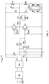
- Figure 1 shows the circuit diagram of an electronic converter for low-voltage halogen lamps. It consists of the function blocks radio interference suppression FE, rectifier GR and a self-excited current-feedback half-bridge converter.
- the radio interference suppression FE protects the network from high-frequency interference signals of the half-bridge converter in a manner known per se and consists, for example, of a suppressor choke and one or more capacitors (see, for example, H.-J. Meyer, Power supplies for practice , Vogel Buchverlag, Würzburg, 1989, pp. 115-116).
- the GR rectifier consists of a full diode bridge (see e.g. W. Hirschmann and A. Hauenstein, Switching power supplies , Siemens AG, 1990, p. 102) and converts the AC voltage of the network into a pulsating DC voltage + U B.
- the negative pole of the rectifier is the reference potential in the following.
- the half-bridge converter essentially consists of the two half-bridge transistors T1, T2, the two half-bridge capacitors C2, C3, the control transformer RKA-RKC for the current feedback and the power transformer TR - a 12 V halogen incandescent lamp HG is operated on its secondary winding - and a trigger generator consisting of the resistor R1, the charging capacitor C1 and the diac DC1.
- the NPN transistor T3 and the series resistor R2 prevent trigger pulses from occurring while the half-bridge is oscillating.
- a resistor R3, R4 and a diode D1, D2 are connected in parallel to each of the two half-bridge capacitors C2, C3.
- the resistors R3, R4 serve to symmetrize the supply voltage.
- the diodes D1, D2 prevent the half-bridge capacitors C2, C3 from charging negatively.
- the protective circuit according to the invention is implemented by a thermistor NTC and a resistance circuit R5-R8.
- the resistance circuit R5-R8 is connected between the reference potential and the diode D2 associated with the bridge transistor T2 connected to the reference potential.
- the resistance circuit R5-R8 consists of the parallel connection of two series connections.
- the series connections each consist of two serial heating resistors R5, R6 and R7, R8.
- an increased current flows through the diode D2 and consequently also through the resistance circuit R5-R8. This causes the heating resistors R5-R8 to heat up.
- EP 0 647 084 A1 for a detailed explanation of the occurrence of the increased current in the event of an overload, reference is made to EP 0 647 084 A1.
- the NTC thermistor is connected in parallel to the charging capacitor C1. If it heats up, e.g. in the event of overload by the resistors R5-R8, its resistance decreases and consequently increasingly short-circuits the charging capacitor C1. As a result, it finally deactivates the trigger generator and prevents the half-bridge converter from starting up again after the following zero crossing of the mains voltage.
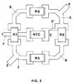
- FIG. 2 the spatial arrangement of the heating resistors R5-R8 and NTC NTC on the circuit board is shown schematically.
- the designation of the components and of the connections corresponds to that in FIG. 1.
- the NTC thermistor and the heating resistors R5-R8 are designed in SMD technology and consequently soldered directly to the associated conductor tracks.
- the heating resistors R5-R8 are arranged on the sides of a square around the NTC thermistor.
- the individual heating resistors are connected to one another by means of four conductor track pieces 5-8.
- the two connections 3, 4 of this resistance circuit are located at two diagonally opposite corners of the arrangement. Viewed from the connections 3, 4, the branching current path of the resistor arrangement thus has the shape of a rhombus.
- the NTC thermistor is connected on its one connection side to a conductor track piece 1 'which is passed under the heating resistor R7 and has the connection 1 at its free end.
- the other connection side of the NTC thermistor is assigned to connection 2 in FIG. 1 and correspondingly connected to connection 4 of the resistor arrangement via conductor track pieces 2 'and 5.
Landscapes
- Engineering & Computer Science (AREA)
- Microelectronics & Electronic Packaging (AREA)
- Control Of Resistance Heating (AREA)
- Circuit Arrangement For Electric Light Sources In General (AREA)
- Circuit Arrangements For Discharge Lamps (AREA)
- Protection Of Static Devices (AREA)
Applications Claiming Priority (2)
| Application Number | Priority Date | Filing Date | Title |
|---|---|---|---|
| DE19613077A DE19613077C2 (de) | 1996-04-02 | 1996-04-02 | Schaltungsanordnung zum Betreiben von elektrischen Lampen, insb. freischwingender Halbbrückenwandler |
| DE19613077 | 1996-04-02 |
Publications (3)
| Publication Number | Publication Date |
|---|---|
| EP0800334A2 true EP0800334A2 (fr) | 1997-10-08 |
| EP0800334A3 EP0800334A3 (fr) | 1999-03-10 |
| EP0800334B1 EP0800334B1 (fr) | 2004-08-04 |
Family
ID=7790206
Family Applications (1)
| Application Number | Title | Priority Date | Filing Date |
|---|---|---|---|
| EP97104698A Expired - Lifetime EP0800334B1 (fr) | 1996-04-02 | 1997-03-19 | Circuit pour alimenter des lampes électriques |
Country Status (5)
| Country | Link |
|---|---|
| US (1) | US5828188A (fr) |
| EP (1) | EP0800334B1 (fr) |
| AU (1) | AU720661B2 (fr) |
| CA (1) | CA2201412C (fr) |
| DE (2) | DE19613077C2 (fr) |
Cited By (2)
| Publication number | Priority date | Publication date | Assignee | Title |
|---|---|---|---|---|
| WO2000028792A2 (fr) * | 1998-11-09 | 2000-05-18 | Lightech Electronics Industries Ltd. | Transformateur electronique pour eclairage |
| EP1701594A1 (fr) | 2005-03-09 | 2006-09-13 | Patent-Treuhand-Gesellschaft für elektrische Glühlampen mbH | Dispositif de protection contre la surcharge pour un convertisseur électronique, par example pour lampes halogènes |
Families Citing this family (13)
| Publication number | Priority date | Publication date | Assignee | Title |
|---|---|---|---|---|
| IT1306778B1 (it) | 1999-02-03 | 2001-10-02 | Antonio Forghieri | Sistema di alimentazione a risparmio energetico per lampadefluorescenti, a controllo elettronico. |
| ITMI991131A1 (it) * | 1999-05-21 | 2000-11-21 | St Microelectronics Srl | Architettura di pilotaggio a semi-ponte (half-bridge) autooscillante a frequenza variabile in particolare per carichi elettrici |
| JP2003522396A (ja) * | 2000-02-10 | 2003-07-22 | コーニンクレッカ フィリップス エレクトロニクス エヌ ヴィ | Ntc抵抗を有する保護回路 |
| US6518711B2 (en) * | 2001-01-19 | 2003-02-11 | Wen-Shin Chao | Halogen lamp electronic transformer |
| US6633139B2 (en) * | 2001-07-02 | 2003-10-14 | Groupe Delta Xfo, Inc. | Converter for converting an AC power main voltage to a voltage suitable for driving a lamp |
| US6856098B2 (en) * | 2001-07-02 | 2005-02-15 | Éclairage Contraste | Converter for converting an AC power main voltage to a voltage suitable for driving a lamp |
| DE10220471A1 (de) * | 2002-05-07 | 2003-11-20 | Patent Treuhand Ges Fuer Elektrische Gluehlampen Mbh | Schaltungsanordnung zum Betrieb von Entladungslampen |
| US6600275B1 (en) * | 2002-05-31 | 2003-07-29 | Arc Technology Co., Ltd. | Remote control and adjustable device for halogen lamp |
| DE102005010129A1 (de) * | 2004-03-05 | 2005-09-15 | Marquardt Gmbh | Elektrische Schaltungsanordnung für ein Elektrowerkzeug |
| US8212495B2 (en) * | 2007-01-22 | 2012-07-03 | Osram Ag | Method for controlling a half-bridge circuit and corresponding half-bridge circuit |
| DE102008064310B3 (de) * | 2008-12-20 | 2010-05-20 | Insta Elektro Gmbh | Elektrisches/elektronisches Installationsgerät |
| GB2482471A (en) * | 2010-06-17 | 2012-02-08 | Wen-Hsin Chao | Transformer for a halogen lamp |
| CN103138244A (zh) * | 2013-01-18 | 2013-06-05 | 杨友林 | 过热保护交流功率控制器件 |
Citations (8)
| Publication number | Priority date | Publication date | Assignee | Title |
|---|---|---|---|---|
| US3702418A (en) * | 1971-09-30 | 1972-11-07 | Texas Instruments Inc | Protection system with manual reset means operable only on clearing of the fault |
| DE2802218A1 (de) * | 1977-01-31 | 1978-08-03 | Philips Nv | Elektronischer starter zum zuenden einer entladungslampe |
| US4230971A (en) * | 1978-09-07 | 1980-10-28 | Datapower, Inc. | Variable intensity control apparatus for operating a gas discharge lamp |
| EP0026571A1 (fr) * | 1979-08-16 | 1981-04-08 | RAYCHEM CORPORATION (a California corporation) | Protection de systèmes électriques par des dispositifs PTC |
| EP0427635A1 (fr) * | 1989-11-09 | 1991-05-15 | Legrand | Dispositif de commande de puissance, notamment variateur de lumière, à protection contre les courts-circuits et les surcharges |
| US5140394A (en) * | 1988-07-26 | 1992-08-18 | Texas Instruments Incorporated | Electrothermal sensor apparatus |
| EP0647084A1 (fr) * | 1993-10-01 | 1995-04-05 | Patent-Treuhand-Gesellschaft für elektrische Glühlampen mbH | Circuit d'alimentation pour une lampe-tungstène halogène à basse tension |
| DE19534056A1 (de) * | 1995-09-14 | 1997-03-20 | Braun Ag | Schaltungsanordnung zur Erkennung einer Übertemperatur aufgrund eines fließenden Stromes |
Family Cites Families (6)
| Publication number | Priority date | Publication date | Assignee | Title |
|---|---|---|---|---|
| US5051661A (en) * | 1989-01-09 | 1991-09-24 | Lee Sang Woo | Protective circuit for fluorescent lamp stabilizer |
| US4968962A (en) * | 1990-01-12 | 1990-11-06 | Therm-O-Disc, Incorporated | Thermal cutoff and resistor assembly |
| US5321337A (en) * | 1992-11-12 | 1994-06-14 | Everay Electronic Co., Ltd. | Ballast having starting current restraint circuitry for preventing a large in-rush current and protection circuitry for preventing damage due to a start-up failure |
| DE4414362A1 (de) * | 1994-02-21 | 1995-08-24 | Tridonic Bauelemente | Elektronischer Transformator |
| DE4416400A1 (de) * | 1994-05-09 | 1995-11-16 | Patent Treuhand Ges Fuer Elektrische Gluehlampen Mbh | Schaltungsanordnung zum Betreiben elektrischer Glühlampen |
| EP0682964B1 (fr) * | 1994-05-17 | 2002-12-11 | Trigam S.A. | Ensemble d'éléments articulés les uns aux autres |
-
1996
- 1996-04-02 DE DE19613077A patent/DE19613077C2/de not_active Expired - Fee Related
-
1997
- 1997-03-19 DE DE59711818T patent/DE59711818D1/de not_active Expired - Lifetime
- 1997-03-19 EP EP97104698A patent/EP0800334B1/fr not_active Expired - Lifetime
- 1997-03-31 US US08/829,904 patent/US5828188A/en not_active Expired - Fee Related
- 1997-04-01 CA CA002201412A patent/CA2201412C/fr not_active Expired - Fee Related
- 1997-04-01 AU AU16645/97A patent/AU720661B2/en not_active Expired
Patent Citations (8)
| Publication number | Priority date | Publication date | Assignee | Title |
|---|---|---|---|---|
| US3702418A (en) * | 1971-09-30 | 1972-11-07 | Texas Instruments Inc | Protection system with manual reset means operable only on clearing of the fault |
| DE2802218A1 (de) * | 1977-01-31 | 1978-08-03 | Philips Nv | Elektronischer starter zum zuenden einer entladungslampe |
| US4230971A (en) * | 1978-09-07 | 1980-10-28 | Datapower, Inc. | Variable intensity control apparatus for operating a gas discharge lamp |
| EP0026571A1 (fr) * | 1979-08-16 | 1981-04-08 | RAYCHEM CORPORATION (a California corporation) | Protection de systèmes électriques par des dispositifs PTC |
| US5140394A (en) * | 1988-07-26 | 1992-08-18 | Texas Instruments Incorporated | Electrothermal sensor apparatus |
| EP0427635A1 (fr) * | 1989-11-09 | 1991-05-15 | Legrand | Dispositif de commande de puissance, notamment variateur de lumière, à protection contre les courts-circuits et les surcharges |
| EP0647084A1 (fr) * | 1993-10-01 | 1995-04-05 | Patent-Treuhand-Gesellschaft für elektrische Glühlampen mbH | Circuit d'alimentation pour une lampe-tungstène halogène à basse tension |
| DE19534056A1 (de) * | 1995-09-14 | 1997-03-20 | Braun Ag | Schaltungsanordnung zur Erkennung einer Übertemperatur aufgrund eines fließenden Stromes |
Cited By (5)
| Publication number | Priority date | Publication date | Assignee | Title |
|---|---|---|---|---|
| WO2000028792A2 (fr) * | 1998-11-09 | 2000-05-18 | Lightech Electronics Industries Ltd. | Transformateur electronique pour eclairage |
| WO2000028792A3 (fr) * | 1998-11-09 | 2000-08-17 | Lightech Electronics Ind Ltd | Transformateur electronique pour eclairage |
| US6157551A (en) * | 1998-11-09 | 2000-12-05 | Lightech Electronics Industries Ltd. | Electronic transformer for lighting |
| EP1701594A1 (fr) | 2005-03-09 | 2006-09-13 | Patent-Treuhand-Gesellschaft für elektrische Glühlampen mbH | Dispositif de protection contre la surcharge pour un convertisseur électronique, par example pour lampes halogènes |
| US7460378B2 (en) | 2005-03-09 | 2008-12-02 | Patent-Treuhand-Gesellschaft Fur Elektrisch Gluhlampen Mbh | Overload protection arrangement for electronic converters, for instance for halogen lamps |
Also Published As
| Publication number | Publication date |
|---|---|
| CA2201412C (fr) | 2005-12-20 |
| DE19613077C2 (de) | 1999-10-14 |
| EP0800334B1 (fr) | 2004-08-04 |
| CA2201412A1 (fr) | 1997-10-02 |
| EP0800334A3 (fr) | 1999-03-10 |
| DE59711818D1 (de) | 2004-09-09 |
| US5828188A (en) | 1998-10-27 |
| AU1664597A (en) | 1997-10-09 |
| AU720661B2 (en) | 2000-06-08 |
| DE19613077A1 (de) | 1997-10-09 |
Similar Documents
| Publication | Publication Date | Title |
|---|---|---|
| EP0800334B1 (fr) | Circuit pour alimenter des lampes électriques | |
| DE4002334C2 (de) | Schaltung zum Betreiben einer elektrischen Entladelampe in einem Kraftfahrzeug | |
| DE602005004257T2 (de) | Überlast-Schutzvorrichtung für elektronische Konverter, zum Beispiel für Halogen Lampen | |
| CH663508A5 (de) | Elektronisches vorschaltgeraet fuer fluoreszenzlampen sowie verfahren zu dessen betrieb. | |
| DE2701661A1 (de) | Stromversorgung fuer leuchtstofflampen | |
| DE10030170A1 (de) | Entladungslampenansteuerschaltung | |
| EP0471332A1 (fr) | Assemblage de circuit pour le fonctionnement d'une lampe fluorescente | |
| DE19849738C2 (de) | Impulsgenerator | |
| DE3621486A1 (de) | Einschaltstromstoss begrenzender schaltkreis | |
| EP0402641A2 (fr) | Chauffage électrique pour voiture | |
| EP0825806A1 (fr) | Circuit pour alimenter des lampes à incandescence | |
| EP0399201B1 (fr) | Système d'alarme pour lumière de flash | |
| DE3022773C2 (fr) | ||
| DE4100349A1 (de) | Elektronisches vorschaltgeraet | |
| EP0389847A2 (fr) | Circuit | |
| DE69915606T2 (de) | Schaltung für entladungslampe | |
| DE102006036292A1 (de) | Vorrichtung und Verfahren zur Überwachung wenigstens einer Leuchtstofflampe | |
| EP0015304B1 (fr) | Procédé et dispositif pour charger un condensateur | |
| DE3530638A1 (de) | Schaltungsanordnung zum starten und betrieb von gasentladungslampen | |
| EP2298036B1 (fr) | Circuit et procédé de fonctionnement d'au moins un dispositif d'éclairage | |
| EP2011373B1 (fr) | Appareil d'allumage à superposition pour lampes à décharge haute pression | |
| EP0055995A1 (fr) | Disposition de circuit d'allumage et fonctionnement d'une lampe de décharge à basse pression à partir d'une source de courant continu | |
| DE4414362A1 (de) | Elektronischer Transformator | |
| EP0682465B1 (fr) | Circuit pour alimenter des lampes à incandescence | |
| EP0668647B1 (fr) | Transformateur électronique |
Legal Events
| Date | Code | Title | Description |
|---|---|---|---|
| PUAI | Public reference made under article 153(3) epc to a published international application that has entered the european phase |
Free format text: ORIGINAL CODE: 0009012 |
|
| AK | Designated contracting states |
Kind code of ref document: A2 Designated state(s): BE DE FR GB IT NL |
|
| PUAL | Search report despatched |
Free format text: ORIGINAL CODE: 0009013 |
|
| AK | Designated contracting states |
Kind code of ref document: A3 Designated state(s): BE DE FR GB IT NL |
|
| 17P | Request for examination filed |
Effective date: 19990406 |
|
| 17Q | First examination report despatched |
Effective date: 20010625 |
|
| GRAP | Despatch of communication of intention to grant a patent |
Free format text: ORIGINAL CODE: EPIDOSNIGR1 |
|
| GRAS | Grant fee paid |
Free format text: ORIGINAL CODE: EPIDOSNIGR3 |
|
| GRAA | (expected) grant |
Free format text: ORIGINAL CODE: 0009210 |
|
| AK | Designated contracting states |
Kind code of ref document: B1 Designated state(s): BE DE FR GB IT NL |
|
| REG | Reference to a national code |
Ref country code: GB Ref legal event code: FG4D Free format text: NOT ENGLISH |
|
| REF | Corresponds to: |
Ref document number: 59711818 Country of ref document: DE Date of ref document: 20040909 Kind code of ref document: P |
|
| GBT | Gb: translation of ep patent filed (gb section 77(6)(a)/1977) |
Effective date: 20040908 |
|
| ET | Fr: translation filed | ||
| PLBE | No opposition filed within time limit |
Free format text: ORIGINAL CODE: 0009261 |
|
| STAA | Information on the status of an ep patent application or granted ep patent |
Free format text: STATUS: NO OPPOSITION FILED WITHIN TIME LIMIT |
|
| 26N | No opposition filed |
Effective date: 20050506 |
|
| PGFP | Annual fee paid to national office [announced via postgrant information from national office to epo] |
Ref country code: NL Payment date: 20110315 Year of fee payment: 15 |
|
| REG | Reference to a national code |
Ref country code: DE Ref legal event code: R409 Ref document number: 59711818 Country of ref document: DE Ref country code: DE Ref legal event code: R119 Ref document number: 59711818 Country of ref document: DE |
|
| REG | Reference to a national code |
Ref country code: DE Ref legal event code: R409 Ref document number: 59711818 Country of ref document: DE |
|
| REG | Reference to a national code |
Ref country code: DE Ref legal event code: R081 Ref document number: 59711818 Country of ref document: DE Owner name: OSRAM GMBH, DE Free format text: FORMER OWNER: OSRAM GESELLSCHAFT MIT BESCHRAENKTER HAFTUNG, 81543 MUENCHEN, DE Effective date: 20111130 |
|
| REG | Reference to a national code |
Ref country code: NL Ref legal event code: V1 Effective date: 20121001 |
|
| REG | Reference to a national code |
Ref country code: DE Ref legal event code: R081 Ref document number: 59711818 Country of ref document: DE Owner name: OSRAM GMBH, DE Free format text: FORMER OWNER: OSRAM AG, 81543 MUENCHEN, DE Effective date: 20130205 |
|
| PG25 | Lapsed in a contracting state [announced via postgrant information from national office to epo] |
Ref country code: NL Free format text: LAPSE BECAUSE OF NON-PAYMENT OF DUE FEES Effective date: 20121001 |
|
| REG | Reference to a national code |
Ref country code: DE Ref legal event code: R081 Ref document number: 59711818 Country of ref document: DE Owner name: OSRAM GMBH, DE Free format text: FORMER OWNER: OSRAM GMBH, 81543 MUENCHEN, DE Effective date: 20130822 |
|
| PGFP | Annual fee paid to national office [announced via postgrant information from national office to epo] |
Ref country code: IT Payment date: 20150326 Year of fee payment: 19 |
|
| PGFP | Annual fee paid to national office [announced via postgrant information from national office to epo] |
Ref country code: GB Payment date: 20150319 Year of fee payment: 19 |
|
| REG | Reference to a national code |
Ref country code: FR Ref legal event code: PLFP Year of fee payment: 20 |
|
| PGFP | Annual fee paid to national office [announced via postgrant information from national office to epo] |
Ref country code: DE Payment date: 20160321 Year of fee payment: 20 |
|
| PGFP | Annual fee paid to national office [announced via postgrant information from national office to epo] |
Ref country code: BE Payment date: 20160321 Year of fee payment: 20 Ref country code: FR Payment date: 20160321 Year of fee payment: 20 |
|
| GBPC | Gb: european patent ceased through non-payment of renewal fee |
Effective date: 20160319 |
|
| PG25 | Lapsed in a contracting state [announced via postgrant information from national office to epo] |
Ref country code: GB Free format text: LAPSE BECAUSE OF NON-PAYMENT OF DUE FEES Effective date: 20160319 |
|
| PG25 | Lapsed in a contracting state [announced via postgrant information from national office to epo] |
Ref country code: IT Free format text: LAPSE BECAUSE OF NON-PAYMENT OF DUE FEES Effective date: 20160319 |
|
| REG | Reference to a national code |
Ref country code: DE Ref legal event code: R071 Ref document number: 59711818 Country of ref document: DE |