EP0800201A2 - Long-life excimer radiator, processes for manufacturing and for increasing the life of such a radiator and device for implementing said processes - Google Patents
Long-life excimer radiator, processes for manufacturing and for increasing the life of such a radiator and device for implementing said processes Download PDFInfo
- Publication number
- EP0800201A2 EP0800201A2 EP97105297A EP97105297A EP0800201A2 EP 0800201 A2 EP0800201 A2 EP 0800201A2 EP 97105297 A EP97105297 A EP 97105297A EP 97105297 A EP97105297 A EP 97105297A EP 0800201 A2 EP0800201 A2 EP 0800201A2
- Authority
- EP
- European Patent Office
- Prior art keywords
- halogen
- discharge space
- radiator
- excimer
- chlorine
- Prior art date
- Legal status (The legal status is an assumption and is not a legal conclusion. Google has not performed a legal analysis and makes no representation as to the accuracy of the status listed.)
- Granted
Links
Images


Classifications
-
- H—ELECTRICITY
- H01—ELECTRIC ELEMENTS
- H01J—ELECTRIC DISCHARGE TUBES OR DISCHARGE LAMPS
- H01J61/00—Gas-discharge or vapour-discharge lamps
- H01J61/70—Lamps with low-pressure unconstricted discharge having a cold pressure < 400 Torr
-
- H—ELECTRICITY
- H01—ELECTRIC ELEMENTS
- H01J—ELECTRIC DISCHARGE TUBES OR DISCHARGE LAMPS
- H01J61/00—Gas-discharge or vapour-discharge lamps
- H01J61/02—Details
- H01J61/12—Selection of substances for gas fillings; Specified operating pressure or temperature
Definitions
- the invention relates to an excimer radiator with a discharge space which contains a halogen-containing filler gas which forms excimers under discharge conditions. Furthermore, the invention relates to a method for producing a long-life excimer radiator and a method for extending the life of such an excimer radiator as well as a device for carrying out the last-mentioned method
- Excimer emitters are used to generate high-energy UV radiation.
- Excimer radiation is also known as silent electrical discharge. This is generated in a discharge space delimited by dielectrics, in which the filling gas forming the excimers is contained.
- An excimer radiator of the type specified is known from EP-A1 0 547 366.
- various noble gases for example argon, krypton or xenon or noble gas mixtures, are proposed as filler gases, depending on the desired spectral composition of the radiation, which contain, for example, chlorine or a chlorine-containing compound, from which one or more chlorine atoms are split off in the discharge will.
- An excimer radiator designed as a planar flat radiator is known from EP-A2 0 521 553.
- the discharge space contains a halogen-containing rare gas filling, the partial pressure of the halogen being between 0.05% and 5% of the partial pressure of the rare gas.
- the well-known excimer radiator is characterized by a high irradiance.
- the maximum adjustable UV irradiance is reduced within the first 300 operating hours.
- the drop in UV irradiance is typically greater than 50% of the initial illuminance.
- the present invention is therefore based on the object of specifying an excimer radiator with a long service life and of providing a method for producing such an excimer radiator. Furthermore, the invention is based on the object of specifying a method for increasing the service life of excimer radiators and a device suitable therefor.
- the object is achieved on the basis of the excimer radiator mentioned at the outset in that the halogen content of the discharge space (16) per cm 2 of its inner surface is at least 1 ⁇ 10 -10 mol / cm 3 and at the same time as a function of the maximum power density of the radiator, expressed in the unit "watts per cm of radiator length" is set to a value in the range from 1 x 10 -7 mol / cm 3 to 1 x 10 -5 mol / cm 3 per unit of power density.
- halogen fluorine, chlorine, bromine and iodine and mixtures of these gases
- ble gas means helium, neon, argon, krypton and xenon and mixtures of these gases.
- the halogen loss can be based on a reaction of the halogen with the inner surfaces of the discharge space.
- the boundary walls of the discharge space can consist, for example, of quartz glass or of a ceramic.
- the surface reaction of the halogen can be avoided by a suitable modification of the inner surfaces delimiting the discharge space.
- such measures are complex and expensive and, moreover, the modifications produced are often not sufficiently resistant to discharge. For example, applied protective layers can peel off.
- the saturation concentration is at a halogen content of at least 1 ⁇ 10 -10 mol / cm 3 per cm 2 of the inner surface.
- This halogen content can be measured in the filling gas before surface reactions with the halogen have taken place, for example before the emitter is started up.
- the halogen content in the discharge space can be determined if all halogen bound to or in the inner surface of the discharge space is added to the halogen content of the filling gas.
- the halogen content bound to or in the inner surface of the discharge space can be determined, for example, by releasing the halogen into the discharge space by means of a suitable temperature treatment.
- This halogen content can also be determined chemically or spectroscopically. It should be noted, however, that such halogen, which delimits the discharge space inside the material Walls may also be present, is not taken into account.
- synthetic quartz glass often contains a certain amount of chlorine due to the manufacturing process.
- the specified saturation concentration of halogens in the discharge space is permanently set, a decrease in the irradiance over time is avoided in whole or in part.
- a halogen concentration above the actually sufficient saturation concentration does not have a detrimental effect on the lifetime behavior. However, it affects the radiation characteristics of the radiator and reduces its maximum power density.
- the halogen concentration to be set continues to depend on the maximum power density of the radiator. On the other hand, it is therefore necessary to observe the further dimensioning rule that the halogen content in the discharge space, depending on the maximum power density of the emitter, expressed in the unit "watt per cm emitter length", to a value in the range from 1 x 10 -7 mol / cm 3 to 1 x 10 -5 mol / cm 3 per unit of power density is set.
- the relationship between the power density and the suitable halogen content of the discharge space has been shown to be approximately linear up to a power density of approximately 200 W / cm lamp length. It can be assumed that this relationship is also valid at even higher power densities, for example at power densities around 400 W / cm.
- the length of the spotlight is only the length of the spotlight that is actually illuminated.
- the stated saturation concentration corresponds approximately to a mixture ratio of halogen: noble gas of 1:50 to 1: 500.
- mixture ratios are only given as a guide for easier orientation. It is expressly pointed out in this connection that it is not the mixing ratio, but the absolute halogen content, based on the size of the inner surface and the volume of the discharge space, and at the same time based on the maximum power density of the excimer radiator, that are decisive for the excimer radiator according to the invention. Any buffer gases in the discharge space, which can also be noble gases, are not taken into account.
- An excimer emitter in which the halogen content of the discharge space per cm 2 of its inner surface is in the range from 1 ⁇ 10 -10 mol / cm 3 to 1 ⁇ 10 -8 mol / cm 3 has proven particularly useful.
- the specified upper limit results from the increasing halogen content decreasing efficiency of the radiator.
- Halogen has a high electronegativity and usually has a lower probability of excitation compared to the noble gas. It therefore captures a relatively large number of electrons; the heater is difficult to ignite if the chlorine content is high.
- the filament density and consequently the halogen content in its atomic form increases with increasing power density of the excimer lamp.
- atomic halogen accumulates particularly easily on the boundary walls of the discharge space.
- the specified upper limit of the halogen concentration is therefore particularly relevant for excimer lamps with a high power density around 100 W per cm of lamp length, while with excimer lamps with a lower power density - without prejudice to the above-mentioned dimensioning rule with regard to the power density - this upper limit can be exceeded.
- An excimer radiator has a particularly long service life, in which the filling gas contains chlorine or a compound which releases chlorine under discharge conditions.
- a suitable chlorine-containing filling gas contains, for example, HCl with 2% Cl 2 and an inert gas, such as krypton, xenon or argon.
- An excimer emitter in which a halogen-containing reservoir is arranged in the discharge space has proven to be particularly advantageous, the concentration of the halogen in the reservoir being higher than that in the filling gas.
- the halogen in the halogen reservoir is separated from the filling gas in the discharge space. If the halogen content falls below a predetermined lower limit, the reservoir can be opened automatically or manually, the halogen contained therein being released into the discharge space.
- the halogen content of the reservoir is dimensioned such that the concentration of the halogen in the discharge space is increased by the release; for example, the target concentration of the halogen in the discharge space can be achieved by the release.
- a suitable halogen content of the reservoir thus results simply from the difference between the concentration at the lower limit and the target concentration and the volume of the discharge space.
- the reservoir has a relatively small volume compared to the volume of the discharge space.
- the halogen concentration in the reservoir is therefore relatively high.
- the reservoir can be designed, for example, in the form of a chamber made of quartz glass or a ceramic, which is broken when the said lower concentration limit is reached.
- the lower concentration limit can be determined on the basis of intensity measurements of the excimer radiation.
- the above-mentioned object is based on the method mentioned at the outset solved in that the inner surfaces of the discharge space are charged with a halogen-containing passivation gas before filling the filling gas.
- This passivation is a relatively simple modification of the inner surface of the discharge space. It can be done, for example, in a simple manner by flushing the discharge space with the halogen.
- the method according to the invention has proven to be particularly effective with regard to the extension of the service life in excimer lamps in which chlorine or a compound which releases chlorine under discharge conditions is used if chlorine is used for the passivation.
- the halogen content of the passivation gas per cm 2 of the inner surface of the discharge space is advantageously at least 1 ⁇ 10 -10 mol / cm 3 , with the proviso that it is chosen to be at least as large as the halogen content in the filling gas.
- the term "halogen content” is understood to mean the concentration of the halogen based on the volume of the discharge space.
- the passivation can take place on walls of the discharge space made of quartz glass at an elevated temperature up to 1000 ° C; with ceramic walls even at higher temperatures.
- the above-mentioned object is achieved according to the invention in that the discharge space is exposed to infrared radiation or that halogen is released from a halogen reservoir arranged in the discharge space.
- the walls delimiting the discharge space are heated by the infrared radiation. These are usually quartz glass walls. It was shown that the warming can reverse a previously depleted halogens in the filling gas.
- the halogen content of the filling gas can be regenerated.
- the loss of halogen has proven to be reversible.
- the reversibility of the halogen loss is accompanied by an extension of the life of the excimer lamp. Due to the temporary loss of halogen within the discharge space and operation with a low halogen content, there is no irreversible damage to the excimer lamp.
- the excimer radiator can be placed in an oven, for example, or it is exposed to the radiation emitted by an infrared radiator.
- halogen is released from a halogen reservoir arranged in the discharge space.
- concentration of the halogen in the reservoir is set higher than that in the filling gas.
- a halogen loss in the discharge space can be compensated for by the additional halogen from the reservoir. If the halogen content falls below a predetermined lower limit, the reservoir can be opened automatically or manually, the halogen contained therein being released into the discharge space.
- a method has proven to be particularly advantageous in which the discharge space is heated to a temperature in the range from 400 ° C. to 1000 ° C. by means of infrared rays.
- This temperature range applies to a discharge space with boundary walls made of quartz glass. If the boundary walls consist of a ceramic, such as Al 2 O 3 , temperatures above 1000 ° C are more favorable.
- Such a procedure has proven to be particularly effective in the case of chlorine-containing filling gas.
- the object stated above is achieved according to the invention in that at least one infrared radiator is provided, which is arranged adjacent to the excimer radiator, in such a way that the infrared radiation emanating from the infrared radiator heats the discharge space.
- the above-described method for extending the excimer radiator can be carried out in a simple manner at any time. To do this, only the infrared heater has to be switched on. The infrared radiation is directed towards the discharge space and heats its boundary walls. This releases the halogen absorbed or adsorbed on it.
- every oven is also suitable as an infrared heater.
- the infrared radiator is advantageously provided with a reflector, which directs the infrared radiation onto the discharge space and thereby prevents the infrared radiation from being emitted undesirably in other directions.
- the length of the infrared radiator or the total length of all infrared radiators corresponds approximately to the length of the discharge space. This effectively releases the halogen over the entire length of the discharge space.
- the infrared radiator advantageously runs or the infrared radiators run parallel to the discharge space of the excimer radiator.
- a device in which the at least one infrared radiator and the excimer radiator are electrically connected to one another in such a way that the infrared radiator is switched on after a definable time interval before or after the excimer radiator is switched on has proven particularly useful.
- This embodiment of the device has the advantage that the halogen is released in a reproducible manner from the inner surfaces delimiting the discharge space.
- Excimer emitters and infrared emitters can be switched on at the same time, so the above-mentioned time interval can also be 0.
- the operating hours are plotted on the X-axis and a relative irradiance on the Y-axis.
- Figure 1 shows the life behavior of XeCl module radiators. These generate a power density of 25 W / cm lamp length.
- the filling pressure of the filling gas in the discharge space is 750 mbar.
- Argon as a buffer gas contributes about 300 mbar to this internal pressure.
- the discharge space in these emitters is formed by the space between two quartz glass tubes which run coaxially to one another.
- the outer diameter of the discharge space is 27 mm, the inner diameter is 16 mm and the length is 343 mm.
- the curve labeled with the reference number 1 represents the service life behavior of a previously available XeCl module radiator.
- the mixing ratio of xenon to chlorine is about 1000: 1.
- the absolute chlorine content in the discharge space is below 1 x 10 -10 mol / cm 3 per cm 2 of the inner surface of the discharge space; more precisely at about 3 x 10 -11 mol / cm 3 : the inside surface of the discharge space is about 470 cm 2 .
- the concentration information relates to the volume of the discharge space.
- the curve shape designated by the reference number 2 represents the service life behavior in a XeCl module radiator in which the chlorine content of the discharge space is quintupled compared to the known excimer radiator described above.
- the mixing ratio of xenon to chlorine is therefore about 200: 1.
- the chlorine content is 1.5 x 10 -10 mol / cm 3 and cm 2 of the inner surface of the discharge space.
- the power density is approximately 30 watts per cm of illuminated spotlight length. Otherwise, the XeCl module radiators considered are identical.
- chlorine accumulates on the inner walls of the discharge space;
- the chlorine content in the filling gas therefore gradually decreases and can drop below the value of, for example, 5 ⁇ 10 -11 mol / cm 3 and cm 2 of the inner surface.
- the service life behavior of the XeCl module radiator according to the invention is characterized by only a slight and, in particular, very slow decrease in the UVB irradiance over time. After approx. 1000 hours of operation, the relative UVB irradiance only decreased by approx. 20%. However, curve 2 does not yet show whether the irradiance amounts to an end value.
- a similar result of the service life behavior results from the creep diagrams of KrCl module radiators shown in FIG . These generate a power density of 25 W / cm lamp length.
- the filling pressure of the filling gas in the discharge space is 350 mbar.
- the discharge space in these emitters is also formed by the space between two quartz glass tubes which run coaxially to one another.
- the outer diameter of the discharge space is 27 mm, the inner diameter is 16 mm and the length is 343 mm.
- reference number 3 is assigned to a creep curve, as is usually measured in a KrCl module radiator according to the prior art.
- the mixing ratio of krypton to chlorine is approximately 1000: 1.
- the absolute chlorine content in this radiator is the same as in the known XeCl module radiator described above.
- a relatively strong drop in UVC radiation intensity can be observed immediately after use of the lamp, which after approx. 300 to 400 operating hours results in a low final value, which is below 10% of the original radiation intensity.
- Curves 4 and 5 are assigned to KrCl module radiators, which differ from one another only in the mixing ratio of the filling gas. These generate a power density of 25 W / cm lamp length. A buffer gas is not included.
- the initial krypton: chlorine mixing ratio is 100: 1
- the creep curve 5 50 1.
- the latter mixing ratio corresponds to a chlorine content of approx. 6 x 10 -10 mol / cm 3 per cm 2 of the inner surface of the discharge space.
- the inside surface of the discharge space is approximately 470 cm 2 .
- the life cycle behavior of KrCl excimer emitters with a relatively low power of 30 W is shown in the creep curves according to FIG .
- the illuminated spotlight length is 10 centimeters. It has been shown that the chlorine loss increases with increasing power density. This is based on the effect already mentioned, according to which the atomic chlorine content increases with increasing filament density, which in turn reacts on the inner walls of the discharge space and is thus removed from the filling gas.
- the creep curve labeled with the reference numeral 6 in turn shows the typical service life curve for commercially available excimer lamps, whereby after an initially strong decrease in UVC irradiance after 350 operating hours, an end value of the irradiance is reached at a low level.
- the initial mixing ratio of chlorine: krypton in the filling gas is 1: 1000.
- the particularly good lifetime behavior of the emitter shown in FIG. 3 is the result of passivation of the inner surface of the discharge space before the filling gas is filled .
- the KrCl excimer emitter according to the invention shows only a slight decrease in the UVC irradiance during the test period of approximately 2000 hours.
- a heat treatment at a temperature of 750 ° C. for a period of one hour.
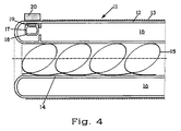
- the excimer radiator 11 consists of an outer quartz glass tube 12, which is covered on its outer surface with a metallic mesh 13, which forms the outer electrode of the excimer radiator 11 and an inner quartz glass tube 14, which is arranged coaxially with the outer quartz glass tube 12 and on the inner wall of which Metallic spiral 15 is present, which forms the inner electrode of the excimer lamp 11.
- the annular gap between the outer quartz glass tube 12 and the inner quartz glass tube 14 corresponds to the discharge space 16 of the excimer radiator 11.
- the volume of the discharge space 16 is approximately 470 cm 3 .
- the power density of the spotlight is 30 watts per cm of the illuminated spot length.
- a quartz glass capsule 17 filled with chlorine is arranged in the discharge space 16.
- the wall of the capsule 17 is scored and in this way provided with a predetermined breaking point 18.
- the chlorine content of the capsule 17 is set such that after breaking the capsule 17, the chlorine content in the discharge space 16 is increased, namely by 1 ⁇ 10 -11 mol / cm 3 and per cm 2 of the inner surface of the discharge space 16.
- a metal part 19 is embedded in the wall of the capsule 17 and shielded from the discharge space 16.
- the metal part 19 together with the capsule 17 is held in an upper position by means of a magnet 20. If the capsule 17 is dropped from this position by removing or switching off the magnet 20, it breaks and the chlorine contained therein escapes into the discharge space 16. In this way, the chlorine content in the discharge space 16 can be regenerated.
- the intensity of a characteristic emission wavelength of the excimer radiator 11 is measured by means of a UV sensor. If the intensity falls below a lower limit, this is indicated optically and the magnet 20 is then removed.
- the magnet 20 is designed as an electromagnet, the magnet 20 is automatically switched off when the intensity falls below a lower limit and the chlorine is thereby released from the capsule 17 into the discharge space 16.
Abstract
Description
Die Erfindung betrifft einen Excimerstrahler mit einem Entladungsraum, der ein unter Entladungsbedingungen Excimere bildendes, halogenhaltiges Füllgas enthält. Weiterhin betrifft die Erfindung ein Verfahren zur Herstellung eines langlebigen Excimerstrahlers sowie ein Verfahren zum Verlängern der Lebensdauer eines solchen Excimerstrahlers sowie eine Vorrichtung zur Durchführung des zuletzt genannten VerfahrensThe invention relates to an excimer radiator with a discharge space which contains a halogen-containing filler gas which forms excimers under discharge conditions. Furthermore, the invention relates to a method for producing a long-life excimer radiator and a method for extending the life of such an excimer radiator as well as a device for carrying out the last-mentioned method
Excimerstrahler werden zur Erzeugung hochenergetischer UV-Strahlung eingesetzt. Die Excimerstrahlung wird auch als stille elektrische Entladung bezeichnet. Diese wird in einem von Dielektrika begrenzten Entladungsraum erzeugt, in dem das die Excimere bildende Füllgas enthalten ist.Excimer emitters are used to generate high-energy UV radiation. Excimer radiation is also known as silent electrical discharge. This is generated in a discharge space delimited by dielectrics, in which the filling gas forming the excimers is contained.
Ein Excimerstrahler der angegebenen Gattung ist aus der EP-A1 0 547 366 bekannt. Bei dem dort beschriebenen Excimerstrahler werden als Füllgase je nach gewünschter spektraler Zusammensetzung der Strahlung verschiedene Edelgase, beispielsweise Argon, Krypton oder Xenon bzw. Edelgasgemische vorgeschlagen, die beispielsweise Chlor oder eine chlorhaltige Verbindung enthalten, aus der in der Entladung ein oder mehrere Chlor-Atome abgespaltet werden.An excimer radiator of the type specified is known from EP-A1 0 547 366. In the excimer radiator described there, various noble gases, for example argon, krypton or xenon or noble gas mixtures, are proposed as filler gases, depending on the desired spectral composition of the radiation, which contain, for example, chlorine or a chlorine-containing compound, from which one or more chlorine atoms are split off in the discharge will.
Über die einzustellende Chlor-Konzentration werden in der EP-A1 0 547 366 keine Angaben gemacht. Bei den bisher im Handel erhältlichen Excimerstrahlern ist der Chlorgehalt in Anlehnung an den Chlorgehalt in den entsprechenden Excimer-Lasern auf ein Mischungsverhältnis von Chlor zu einem Edelgas bzw. zu einem Edelgasgemisch von 1/1000 eingestellt. Ein derartiger Excimerstrahler ist beispielsweise in der Promotionsarbeit von Herrn Volker Shorpp mit dem Titel "Die dielektrisch behinderte Edelgas-Halogen-Excimer-Entladung: eine neuartige UV-Strahlenquelle", Universität Karlsruhe, 1991, beschrieben.No information is given in EP-
Aus der EP-A2 0 521 553 ist ein als planarer Flachstrahler ausgebildeter Excimerstrahler bekannt. Der Entladungsraum enthält eine halogenhaltige Edelgasfüllung, wobei der Partialdruck des Halogens zwischen 0.05% und 5% des Partialdruckes des Edelgases beträgt. Der bekannte Excimerstrahler zeichnet sich durch eine hohe Bestrahlungsstärke aus.An excimer radiator designed as a planar flat radiator is known from EP-A2 0 521 553. The discharge space contains a halogen-containing rare gas filling, the partial pressure of the halogen being between 0.05% and 5% of the partial pressure of the rare gas. The well-known excimer radiator is characterized by a high irradiance.
Bei den bisher bekannten Excimerstrahlern verringert sich die maximal einstellbare UV-Bestrahlungsstärke bereits innerhalb der ersten 300 Betriebsstunden. Der Abfall der UV-Bestrahlungsstärke ist typischerweise größer als 50 % der anfänglichen Bestrahlungsstärke.With the excimer lamps known to date, the maximum adjustable UV irradiance is reduced within the first 300 operating hours. The drop in UV irradiance is typically greater than 50% of the initial illuminance.
Ein Versuch, die Lebensdauer eines solchen Strahlers zu verlängern, ist in der EP-A1 607 960 erläutert. Darin wird ein Excimerstrahler beschrieben, der einen mit einem geeigneten Füllgas gefüllten, gasdicht verschlossenen Entladungsraum aufweist. Zum Zweck der Lebensdauerverlängerung des Strahlers wird vorgeschlagen, gasförmige Verunreinigungen des Füllgases zu entfernen und hierfür ein "Getter" vorzusehen, das innerhalb des Entladungsraumes oder in Verbindung mit diesem angeordnet sein kann. Es hat sich aber gezeigt, daß das Entfernen von Füllgas-Verunreinigungen für eine deutliche Erhöhung der Lebensdauer nicht ausreicht.An attempt to extend the life of such a radiator is explained in EP-A1 607 960. An excimer radiator is described therein which has a discharge space which is filled with a suitable filling gas and is sealed in a gastight manner. For the purpose of extending the life of the radiator, it is proposed to remove gaseous contaminants from the filling gas and to provide a "getter" for this purpose, which can be arranged inside the discharge space or in connection with it. However, it has been shown that the removal of fill gas impurities is not sufficient for a significant increase in the service life.
Der vorliegenden Erfindung liegt daher die Aufgabe zugrunde, einen Excimerstrahler mit hoher Lebensdauer anzugeben sowie ein Verfahren zur Herstellung eines solchen Excimerstrahlers bereitzustellen. Weiterhin liegt der Erfindung die Aufgabe zugrunde, ein Verfahren zur Erhöhung der Lebensdauer von Excimerstrahlern und eine dafür geeignete Vorrichtung anzugeben.The present invention is therefore based on the object of specifying an excimer radiator with a long service life and of providing a method for producing such an excimer radiator. Furthermore, the invention is based on the object of specifying a method for increasing the service life of excimer radiators and a device suitable therefor.
Hinsichtlich des Excimerstrahlers wird die Aufgabe ausgehend von dem eingangs genannten Excimerstrahler dadurch gelöst, daß der Halogengehalt des Entladungsraumes (16) pro cm2 seiner Innenoberfläche mindestens 1 x 10⁻¹⁰ mol/cm3 beträgt und gleichzeitig in Abhängigkeit von der maximalen Leistungsdichte des Strahlers, ausgedrückt in der Einheit "Watt pro cm Strahlerlänge" auf einen Wert im Bereich von 1 x 10⁻⁷ mol/cm3 bis 1 x 10⁻⁵ mol/cm3 pro Einheit der Leistungsdichte eingestellt ist.With regard to the excimer radiator, the object is achieved on the basis of the excimer radiator mentioned at the outset in that the halogen content of the discharge space (16) per cm 2 of its inner surface is at least 1 × 10 -10 mol / cm 3 and at the same time as a function of the maximum power density of the radiator, expressed in the unit "watts per cm of radiator length" is set to a value in the range from 1 x 10 -7 mol / cm 3 to 1 x 10 -5 mol / cm 3 per unit of power density.
Es wurde gefunden, daß nicht in erster Linie Verunreinigungen des Füllgases für die Abnahme der UV-Bestrahlungsstärke bei den bekannten Excimerstrahlern verantwortlich sind, sondern eine Verarmung des Füllgases an Halogenen. Unter "Halogen" werden im folgenden Fluor, Chlor, Brom und Jod sowie Mischungen dieser Gase; unter "Edelgas" Helium, Neon, Argon, Krypton und Xenon sowie Mischungen dieser Gase verstanden. Enthält das Füllgas Verbindungen, die unter Entladungsbedingungen Halogene abgeben, so sind die unter Entladungsbedingungen tatsächlich freigesetzten Halogenkonzentrationen relevant. Es hat sich gezeigt, daß die Freisetzung der Halogene im wesentlichen von der Leistungsdichte abhängt, mit der der Strahler betrieben wird.It was found that it is not primarily impurities in the filling gas that are responsible for the decrease in the UV irradiance in the known excimer lamps, but rather a depletion of the filling gas in halogens. In the following "halogen" fluorine, chlorine, bromine and iodine and mixtures of these gases; “noble gas” means helium, neon, argon, krypton and xenon and mixtures of these gases. Contains the fill gas Compounds which release halogens under discharge conditions are relevant to the halogen concentrations actually released under discharge conditions. It has been shown that the release of the halogens essentially depends on the power density with which the emitter is operated.
Der Halogenverlust kann auf einer Reaktion des Halogens mit den Innenoberflächen des Entladungsraumes beruhen. Die Begrenzungswände des Entladungsraumes können beispielsweise aus Quarzglas bestehen oder aus einer Keramik. Die Oberflächenreaktion des Halogens läßt sich zwar durch eine geeignete Modifikation der den Entladungsraum begrenzenden Innenoberflächen vermeiden. Derartige Maßnahmen sind jedoch aufwendig und teuer und die erzeugten Modifikationen sind überdies häufig nicht ausreichend beständig gegenüber der Entladung. So können beispielsweise aufgebrachte Schutzschichten abblättern.The halogen loss can be based on a reaction of the halogen with the inner surfaces of the discharge space. The boundary walls of the discharge space can consist, for example, of quartz glass or of a ceramic. The surface reaction of the halogen can be avoided by a suitable modification of the inner surfaces delimiting the discharge space. However, such measures are complex and expensive and, moreover, the modifications produced are often not sufficiently resistant to discharge. For example, applied protective layers can peel off.
Es wurde gefunden, daß bereits eine Lebensdauerverlängerung durch eine anfänglich erhöhte Halogen-Konzentration im Füllgas erzielt werden kann. Dies kann darauf zurückgeführt werden, daß an der Innenoberfläche des Entladungsraumes kein stetiger Verbrauch an Halogen stattfindet, sondern vielmehr mit steigenden Angebot an Halogen im Füllgas eine Sättigung der Oberflächenreaktion zu beobachten ist. Derjenige Halogengehalt im Füllgas, ab dem diese Sättigung zu beobachten ist und bei dem darüberhinaus eine für die Excimer-Entladung ausreichende Halogen-Konzentration innerhalb des Entladungsraumes vorhanden ist, wird nachfolgend als Sättigungskonzentration bezeichnet. Die Sättigungskonzentration hängt von der Betriebstemperatur des Excimer-Strahlers, insbesondere aber von seiner Leistung und von der Größe der Innenoberfläche des Entladungsraumes ab. Es wurde gefunden, daß die Sättigungskonzentration bezogen auf die Innenoberfläche des Entladungsraumes bei einem Halogengehalt von mindestens 1 x 10⁻¹⁰ mol/cm3 pro cm2 der Innenoberfläche liegt. Dieser Halogengehalt kann im Füllgas gemessen werden, bevor Oberflächenreaktionen mit dem Halogen stattgefunden haben, also beispielsweise vor der Inbetriebnahme des Strahlers. Für den Fall, daß die Innenoberflächen des Entladungsraumes vorab mit dem Halogen beladen worden sind oder nach einer Inbetriebnahme des Strahlers kann der Halogengehalt im Entladungsraum ermittelt werden, wenn zu dem Halogengehalt des Füllgases sämtliches an oder in der Innenoberfläche des Entladungsraumes gebundenes Halogen hinzugerechnet wird. Die Ermittlung des an oder in der Innenoberfläche des Entladungsraumes gebundenen Halogen-Gehaltes kann beispielsweise durch Freisetzung des Halogens in den Entladungsraum durch eine geeignete Temperaturbehandlung erfolgen. Dieser Halogen-Gehalt kann aber auch auf chemischem oder spektroskopischem Weg ermittelt werden. Dabei ist aber zu beachten, daß solches Halogen, das im Innern des Materials der den Entladungsraum begrenzenden Wandungen möglicherweise zusätzlich vorhanden ist, nicht berücksichtigt wird. Beispielsweise enthält synthetisches Quarzglas herstellungsbedingt häufig einen gewissen Chlorgehalt.It has been found that an extension of the service life can be achieved by an initially increased halogen concentration in the filling gas. This can be attributed to the fact that there is no constant consumption of halogen on the inner surface of the discharge space, but rather a saturation of the surface reaction can be observed with increasing supply of halogen in the filling gas. The halogen content in the filling gas above which this saturation can be observed and at which there is also a sufficient halogen concentration within the discharge space for the excimer discharge is referred to below as the saturation concentration. The saturation concentration depends on the operating temperature of the excimer radiator, but in particular on its power and on the size of the inner surface of the discharge space. It has been found that the saturation concentration, based on the inner surface of the discharge space, is at a halogen content of at least 1 × 10 -10 mol / cm 3 per cm 2 of the inner surface. This halogen content can be measured in the filling gas before surface reactions with the halogen have taken place, for example before the emitter is started up. In the event that the inner surfaces of the discharge space have been loaded with the halogen beforehand or after the emitter has been started up, the halogen content in the discharge space can be determined if all halogen bound to or in the inner surface of the discharge space is added to the halogen content of the filling gas. The halogen content bound to or in the inner surface of the discharge space can be determined, for example, by releasing the halogen into the discharge space by means of a suitable temperature treatment. This halogen content can also be determined chemically or spectroscopically. It should be noted, however, that such halogen, which delimits the discharge space inside the material Walls may also be present, is not taken into account. For example, synthetic quartz glass often contains a certain amount of chlorine due to the manufacturing process.
Ist die angegebene Sättigungskonzentration an Halogenen im Entladungsraum dauerhaft eingestellt, wird eine Abnahme der Bestrahlungsstärke mit der Zeit ganz oder teilweise vermieden. Eine Halogenkonzentration oberhalb der tatsächlich ausreichenden Sättigungskonzentration wirkt sich auf das Lebensdauerverhalten nicht schädlich aus. Sie beeinflußt aber die Abstrahlcharakteristik des Strahlers und verringert seine maximale Leistungsdichte. Die einzustellende Halogenkonzentration richtet sich aber weiterhin nach der maximalen Leistungsdichte des Strahlers. Es ist daher andererseits die weitere Bemessungsregel zu beachten, daß der Halogengehalt im Entladungsraum in Abhängigkeit von der maximalen Leistungsdichte des Strahlers, ausgedrückt in der Einheit "Watt pro cm Strahlerlänge" auf einen Wert im Bereich von 1 x 10⁻⁷ mol/cm3 bis 1 x 10⁻⁵ mol/cm3 pro Einheit der Leistungsdichte eingestellt wird.If the specified saturation concentration of halogens in the discharge space is permanently set, a decrease in the irradiance over time is avoided in whole or in part. A halogen concentration above the actually sufficient saturation concentration does not have a detrimental effect on the lifetime behavior. However, it affects the radiation characteristics of the radiator and reduces its maximum power density. The halogen concentration to be set continues to depend on the maximum power density of the radiator. On the other hand, it is therefore necessary to observe the further dimensioning rule that the halogen content in the discharge space, depending on the maximum power density of the emitter, expressed in the unit "watt per cm emitter length", to a value in the range from 1 x 10 -7 mol / cm 3 to 1 x 10 -5 mol / cm 3 per unit of power density is set.
Der angegebene Zusammenhang zwischen der Leistungsdichte und dem geeigneten Halogengehalt des Entladungsraumes hat sich bis zu einer Leistungsdichte von ca. 200 W/cm Strahlerlänge als annähernd linear erwiesen. Es kann angenommen werden, daß dieser Zusammenhang auch bei noch höheren Leistungsdichten, beispielsweise bei Leistungsdichten um 400 W/cm, gültig ist. Als Strahlerlänge gilt dabei nur die tatsächlich beleuchtete Länge des Strahlers.The relationship between the power density and the suitable halogen content of the discharge space has been shown to be approximately linear up to a power density of approximately 200 W / cm lamp length. It can be assumed that this relationship is also valid at even higher power densities, for example at power densities around 400 W / cm. The length of the spotlight is only the length of the spotlight that is actually illuminated.
Es stellt für den Fachmann kein Problem dar, ausgehend von der Lehre des Patentanspruches, den Halogengehalt auf die konkreten Strahler-Geometrien und -leistungen einzustellen.Based on the teaching of the patent claim, it is no problem for the person skilled in the art to adjust the halogen content to the specific radiator geometries and outputs.
Bei den üblichen Excimerstrahlern entspricht die angegebene Sättigungskonzentration etwa einem Mischungsverhältnis von Halogen : Edelgas von 1 : 50 bis 1 : 500. Diese Mischungsverhältnisse werden nur als Anhaltspunkte zur leichteren Orientierung mitgeteilt. Es wird in diesem Zusammenhang ausdrücklich darauf hingewiesen, daß nicht das Mischungsverhältnis, sondern der absolute Halogengehalt, bezogen auf die Größe der Innenoberfläche und das Volumen des Entladungsraumes, und gleichzeitig bezogen auf die maximale Leistungsdichte des Excimerstrahlers, für den erfindungsgemäßen Excimerstrahler entscheidend sind. Dabei werden etwaige Puffergase im Entladungsraum, die ebenfalls Edelgase sein können, außer Betracht gelassen.In the case of the usual excimer emitters, the stated saturation concentration corresponds approximately to a mixture ratio of halogen: noble gas of 1:50 to 1: 500. These mixture ratios are only given as a guide for easier orientation. It is expressly pointed out in this connection that it is not the mixing ratio, but the absolute halogen content, based on the size of the inner surface and the volume of the discharge space, and at the same time based on the maximum power density of the excimer radiator, that are decisive for the excimer radiator according to the invention. Any buffer gases in the discharge space, which can also be noble gases, are not taken into account.
Besonders bewährt hat sich ein Excimerstrahler, bei dem der Halogengehalt des Entladungsraumes pro cm2 seiner Innenoberfläche im Bereich von 1 x 10⁻¹⁰ mol/cm3 bis 1 x 10⁻⁸ mol/cm3 liegt. Die angegebene Obergrenze ergibt sich aus dem bei zunehmendem Halogengehalt abnehmenden Wirkungsgrad des Strahlers. Das Halogen hat eine hohe Elektronegativität und üblicherweise gegenüber dem Edelgas eine geringere Anregungswahrscheinlichkeit. Es fängt deshalb relativ viele Elektronen ab; der Strahler ist bei hohem Chlorgehalt schwer zu zünden. Andererseits nimmt mit zunehmender Leistungsdichte des Excimerstrahlers die Filamentdichte und in Folge davon der Halogengehalt in seiner atomaren Form zu. Atomares Halogen lagert sich jedoch an den Begrenzungswandungen des Entladungsraumes besonders leicht an. Die angegebene Obergrenze der Halogen-Konzentration ist daher insbesondere für Excimerstrahler mit hoher Leistungsdichte um 100 W pro cm Strahlerlänge relevant, während bei Excimerstrahlern mit niedrigerer Leistungsdichte - unbeschadet der oben angebenen Bemessungsregel in Bezug auf die Leistungsdichte - diese Obergrenze eher unterschritten werden kann.An excimer emitter in which the halogen content of the discharge space per cm 2 of its inner surface is in the range from 1 × 10 -10 mol / cm 3 to 1 × 10 -8 mol / cm 3 has proven particularly useful. The specified upper limit results from the increasing halogen content decreasing efficiency of the radiator. Halogen has a high electronegativity and usually has a lower probability of excitation compared to the noble gas. It therefore captures a relatively large number of electrons; the heater is difficult to ignite if the chlorine content is high. On the other hand, the filament density and consequently the halogen content in its atomic form increases with increasing power density of the excimer lamp. However, atomic halogen accumulates particularly easily on the boundary walls of the discharge space. The specified upper limit of the halogen concentration is therefore particularly relevant for excimer lamps with a high power density around 100 W per cm of lamp length, while with excimer lamps with a lower power density - without prejudice to the above-mentioned dimensioning rule with regard to the power density - this upper limit can be exceeded.
Eine besonders hohe Lebensdauer weist ein Excimerstrahler auf, bei dem das Füllgas Chlor oder eine unter Entladungsbedingungen Chlor abgebende Verbindung enthält. Ein geeignetes chlorhaltiges Füllgas enthält beispielsweise HCl mit 2 % Cl2 und ein Edelgas, wie beispielsweise Krypton, Xenon oder Argon.An excimer radiator has a particularly long service life, in which the filling gas contains chlorine or a compound which releases chlorine under discharge conditions. A suitable chlorine-containing filling gas contains, for example, HCl with 2% Cl 2 and an inert gas, such as krypton, xenon or argon.
Als besonders vorteilhaft hat sich ein Excimerstrahler erwiesen, bei dem im Entladungsraum ein das Halogen enthaltendes Reservoir angeordnet ist, wobei die Konzentration des Halogens im Reservoir höher ist als diejenige im Füllgas. Das Halogen im Halogenreservoir ist vom Füllgas des Entladungsraumes getrennt. Fällt der Halogengehalt unter eine vorgegebene Untergrenze, kann das Reservoir automatisch oder manuell geöffnet werden, wobei das darin enthaltene Halogen in den Entladungsraum freigesetzt wird. Der Halogengehalt des Reservoirs ist dabei so bemessen, daß durch die Freisetzung die Konzentration des Halogens im Entladungsraum erhöht wird, beispielsweise kann durch die Freisetzung die Soll-Konzentration des Halogens im Entladungsraum erreicht werden. Ein geeigneter Halogengehalt des Reservoirs ergibt sich somit einfach aufgrund der Differenz zwischen der Konzentration bei der Untergrenze und der Soll-Konzentration sowie dem Volumen des Entladungsraumes. Das Reservoir hat ein relativ kleines Volumen, verglichen mit dem Volumen des Entladungsraumes. Die Halogenkonzentration im Reservoir ist daher relativ hoch. Das Reservoir kann beispielsweise in Form einer Kammer aus Quarzglas oder einer Keramik ausgebildet sein, die bei Erreichen der genannten Konzentrations-Untergrenze zerbrochen wird. Die Konzentrations-Untergrenze kann anhand von Intensitätsmessungen der Excimerstrahlung ermittelt werden.An excimer emitter in which a halogen-containing reservoir is arranged in the discharge space has proven to be particularly advantageous, the concentration of the halogen in the reservoir being higher than that in the filling gas. The halogen in the halogen reservoir is separated from the filling gas in the discharge space. If the halogen content falls below a predetermined lower limit, the reservoir can be opened automatically or manually, the halogen contained therein being released into the discharge space. The halogen content of the reservoir is dimensioned such that the concentration of the halogen in the discharge space is increased by the release; for example, the target concentration of the halogen in the discharge space can be achieved by the release. A suitable halogen content of the reservoir thus results simply from the difference between the concentration at the lower limit and the target concentration and the volume of the discharge space. The reservoir has a relatively small volume compared to the volume of the discharge space. The halogen concentration in the reservoir is therefore relatively high. The reservoir can be designed, for example, in the form of a chamber made of quartz glass or a ceramic, which is broken when the said lower concentration limit is reached. The lower concentration limit can be determined on the basis of intensity measurements of the excimer radiation.
Hinsichtlich des Verfahrens zur Herstellung eines langlebigen Excimerstrahlers wird die oben angegebene Aufgabe ausgehend von dem eingangs genannten Verfahren erfindungsgemäß dadurch gelöst, daß die Innenoberflächen des Entladungsraumes vor dem Einfüllen des Füllgases mit einem halogenhaltigen Passivierungsgas beaufschlagt werden.With regard to the method for producing a long-life excimer radiator, the above-mentioned object is based on the method mentioned at the outset solved in that the inner surfaces of the discharge space are charged with a halogen-containing passivation gas before filling the filling gas.
Es wurde festgestellt, daß ein höherer Halogenanteil im Füllgas des Entladungsraumes dann nicht erforderlich ist, wenn die Innenoberflächen des Entladungsraumes vor dem Einfüllen des Füllgases mit einem Halogen behandelt worden sind. Diese Vorbehandlung mit Halogen "passiviert" sozusagen die Innenoberflächen des Entladungsraumes. Durch die Passivierung werden die Innenoberflächen mit Halogen gesättigt und dadurch beim späteren Betrieb des Excimerstrahlers der weitere Verbrauch von Halogen aus dem Füllgas aufgrund Absorption in, Adsorption an oder chemischer Reaktion mit den Begrenzungswänden des Entladungsraumes gesenkt oder sogar verhindert.It has been found that a higher proportion of halogen in the filling gas of the discharge space is not necessary if the inner surfaces of the discharge space have been treated with a halogen before the filling gas has been filled in. This pretreatment with halogen "passivates" the inner surfaces of the discharge space, so to speak. Passivation causes the inner surfaces to be saturated with halogen, which means that the subsequent consumption of halogen from the filling gas due to absorption in, adsorption on or chemical reaction with the boundary walls of the discharge space is reduced or even prevented during later operation of the excimer lamp.
Bei dieser Passivierung handelt es sich um eine verhältnismäßig einfach durchzuführende Modifizierung der Innenoberfläche des Entladungsraumes. Sie kann beispielsweise auf einfache Weise durch Spülen des Entladungsraumes mit dem Halogen erfolgen.This passivation is a relatively simple modification of the inner surface of the discharge space. It can be done, for example, in a simple manner by flushing the discharge space with the halogen.
Als besonders wirkungsvoll hinsichtlich der Lebensdauerverlängerung hat sich das erfindungsgemäße Verfahren bei Excimerstrahlern erwiesen, bei denen Chlor oder eine unter Entladungsbedingungen Chlor abgebende Verbindung eingesetzt wird, wenn zur Passivierung Chlor verwendet wird.The method according to the invention has proven to be particularly effective with regard to the extension of the service life in excimer lamps in which chlorine or a compound which releases chlorine under discharge conditions is used if chlorine is used for the passivation.
Der Halogengehalt des Passivierungsgases pro cm2 der Innenoberfläche des Entladungsraumes beträgt vorteilhafterweise mindestens 1 x 10⁻¹⁰ mol/cm3, mit der Maßgabe, daß er mindestens so groß gewählt wie der Halogengehalt im Füllgas. Unter dem Ausdruck "Halogengehalt" wird dabei die Konzentration des Halogens bezogen auf das Volumen des Entladungsraumes verstanden. Das Passivieren kann bei Wandungen des Entladungsraumes aus Quarzglas bei einer erhöhten Temperatur bis 1000°C erfolgen; bei Wandungen aus Keramik auch noch bei höheren Temperaturen.The halogen content of the passivation gas per cm 2 of the inner surface of the discharge space is advantageously at least 1 × 10 -10 mol / cm 3 , with the proviso that it is chosen to be at least as large as the halogen content in the filling gas. The term "halogen content" is understood to mean the concentration of the halogen based on the volume of the discharge space. The passivation can take place on walls of the discharge space made of quartz glass at an elevated temperature up to 1000 ° C; with ceramic walls even at higher temperatures.
Hinsichtlich des Verfahrens zur Verlängerung der Lebensdauer eines Excimerstrahlers wird die oben angegebene Aufgabe erfindungsgemäß dadurch gelöst, daß der Entladungsraum mit Infrarotstrahlung beaufschlagt wird oder, daß Halogen aus einem im Entladungsraum angeordneten Halogenreservoir freigesetzt wird.With regard to the method for extending the lifespan of an excimer radiator, the above-mentioned object is achieved according to the invention in that the discharge space is exposed to infrared radiation or that halogen is released from a halogen reservoir arranged in the discharge space.
Bei der ersten Alternative des Verfahrens werden durch die Infrarotstrahlung die den Entladungsraum begrenzenden Wandungen erwärmt. Hierbei handelt es sich üblicherweise um Wandungen aus Quarzglas. Es zeigte sich, daß durch die Erwärmung eine vorher eingetretene Verarmung des Füllgases an Halogenen wieder rückgängig gemacht werden kann.In the first alternative of the method, the walls delimiting the discharge space are heated by the infrared radiation. These are usually quartz glass walls. It was shown that the warming can reverse a previously depleted halogens in the filling gas.
Ursprünglich war angenommen worden, daß das Halogen am Quarzglas fest absorbiert ist oder mit dem Silizium des Quarzglases eine stabile chemische Verbindung bildet.Originally, it was assumed that the halogen is firmly absorbed on the quartz glass or forms a stable chemical bond with the silicon of the quartz glass.
Durch eine Beaufschlagung des Excimerstrahlers mit Infrarotstrahlung entweder während des Betriebes oder auch in einer Ruhephase bei abgeschaltetem Excimerstrahler kann das Füllgas hinsichtlich seines Halogengehaltes regeneriert werden. Der eingetretene Halogenverlust hat sich insoweit als reversibel erwiesen. Überraschenderweise geht die Reversibilität des Halogenverlustes mit einer Verlängerung der Lebensdauer des Excimerstrahlers einher. Durch den vorübergehenden Halogenverlust innerhalb des Entladungsraumes und einen Betrieb bei geringem Halogengehalt entstehen demnach keine irreversiblen Schädigungen des Excimerstrahlers.By applying infrared radiation to the excimer radiator either during operation or in a resting phase when the excimer radiator is switched off, the halogen content of the filling gas can be regenerated. In this respect, the loss of halogen has proven to be reversible. Surprisingly, the reversibility of the halogen loss is accompanied by an extension of the life of the excimer lamp. Due to the temporary loss of halogen within the discharge space and operation with a low halogen content, there is no irreversible damage to the excimer lamp.
Für die Beaufschlagung mit Infrarot-Strahlung kann der Excimerstrahler beispielsweise in einen Ofen eingebracht werden, oder er wird der von einem Infrarotstrahler ausgehenden Strahlung ausgesetzt.For exposure to infrared radiation, the excimer radiator can be placed in an oven, for example, or it is exposed to the radiation emitted by an infrared radiator.
Bei der zweiten Alternative des erfindungsgemäßen Verfahrens wird Halogen aus einem im Entladungsraum angeordneten Halogenreservoir freigesetzt. Die Konzentration des Halogens im Reservoir ist höher eingestellt als diejenige im Füllgas. Durch das zusätzliche Halogen aus dem Reservoir kann ein Halogenverlust im Entladungsraum ausgeglichen werden. Fällt der Halogengehalt unter eine vorgegebene Untergrenze, kann das Reservoir automatisch oder manuell geöffnet werden, wobei das darin enthaltene Halogen in den Entladungsraum freigesetzt wird. Hinsichtlich der Ausbildung des Halogen-Reservoirs, seinem Halogengehalt und der Ermittlung der Konzentrations-Untergrenze der wird auf die obigen Erläuterungen verwiesen.In the second alternative of the method according to the invention, halogen is released from a halogen reservoir arranged in the discharge space. The concentration of the halogen in the reservoir is set higher than that in the filling gas. A halogen loss in the discharge space can be compensated for by the additional halogen from the reservoir. If the halogen content falls below a predetermined lower limit, the reservoir can be opened automatically or manually, the halogen contained therein being released into the discharge space. With regard to the formation of the halogen reservoir, its halogen content and the determination of the lower concentration limit, reference is made to the above explanations.
Als besonders vorteilhaft hat sich ein Verfahren erwiesen, bei dem der Entladungsraum mittels Infrarotstrahlen auf eine Temperatur im Bereich von 400 °C bis 1000 °C erwärmt wird. Dieser Temperaturbereich gilt für einen Entladungsraum mit Begrenzungswandungen aus Quarzglas. Bestehen die Begrenzungswandungen aus einer Keramik, wie beispielsweise Al2O3, sind Temperaturen oberhalb 1000 °C günstiger. Eine derartige Verfahrensweise hat sich insbesondere bei chlorhaltigem Füllgas als besonders wirkungsvoll erwiesen.A method has proven to be particularly advantageous in which the discharge space is heated to a temperature in the range from 400 ° C. to 1000 ° C. by means of infrared rays. This temperature range applies to a discharge space with boundary walls made of quartz glass. If the boundary walls consist of a ceramic, such as Al 2 O 3 , temperatures above 1000 ° C are more favorable. Such a procedure has proven to be particularly effective in the case of chlorine-containing filling gas.
Hinsichtlich der Vorrichtung zur Durchführung des Verfahrens zur Lebensdauerverlängerung eines Excimerstrahlers wird die oben angegebene Aufgabe erfindungsgemäß dadurch gelöst, daß mindestens ein Infrarotstrahler vorgesehen ist, der benachbart zum Excimerstrahler angeordnet ist, derart, daß die vom Infrarotstrahler ausgehende Infrarotstrahlung den Entladungsraum erwärmt.With regard to the device for carrying out the method for extending the life of an excimer radiator, the object stated above is achieved according to the invention in that at least one infrared radiator is provided, which is arranged adjacent to the excimer radiator, in such a way that the infrared radiation emanating from the infrared radiator heats the discharge space.
Durch die Anordnung von Excimerstrahler und Infrarotstrahler nebeneinander kann das oben erläuterte Verfahren zum Verlängern des Excimerstrahlers jederzeit auf einfache Weise durchgeführt werden. Hierzu muß lediglich der Infrarotstrahler eingeschaltet werden. Die Infrarotstrahlung ist dabei auf den Entladungsraum gerichtet und erwärmt dessen Begrenzungswandungen. Dadurch wird das daran absorbierte oder adsorbierte Halogen freigesetzt.By arranging the excimer radiator and the infrared radiator next to one another, the above-described method for extending the excimer radiator can be carried out in a simple manner at any time. To do this, only the infrared heater has to be switched on. The infrared radiation is directed towards the discharge space and heats its boundary walls. This releases the halogen absorbed or adsorbed on it.
Als Infrarotstrahler ist grundsätzlich auch jeder Ofen geeignet. Vorteilhafterweise ist der Infrarotstrahler mit einem Reflektor versehen, der die Infrarotstrahlung auf den Entladungsraum richtet und dadurch ein unerwünschtes Abstrahlen der Infrarotstrahlung in andere Richtungen verhindert.In principle, every oven is also suitable as an infrared heater. The infrared radiator is advantageously provided with a reflector, which directs the infrared radiation onto the discharge space and thereby prevents the infrared radiation from being emitted undesirably in other directions.
In einer bevorzugten Ausführungsform der Vorrichtung entspricht die Länge des Infrarotstrahlers oder die Gesamtlänge aller Infrarotstrahler etwa der Länge des Entladungsraumes. Dadurch wird das Halogen über die gesamte Länge des Entladungsraumes wirksam freigesetzt. Vorteilhafterweise verläuft der Infrarotstrahler bzw. verlaufen die Infrarotstrahler dabei parallel zum Entladungsraum des Excimerstrahlers.In a preferred embodiment of the device, the length of the infrared radiator or the total length of all infrared radiators corresponds approximately to the length of the discharge space. This effectively releases the halogen over the entire length of the discharge space. The infrared radiator advantageously runs or the infrared radiators run parallel to the discharge space of the excimer radiator.
Besonders bewährt hat sich eine Vorrichtung, bei der der mindestens eine Infrarotstrahler und der Excimerstrahler elektrisch miteinander derart verbunden sind, daß nach einem bestimmbaren Zeitintervall vor oder nach Einschalten des Excimerstrahlers der Infrarotstrahler eingeschaltet wird. Diese Ausführungsform der Vorrichtung hat den Vorteil, daß die Freisetzung des Halogens von den den Entladungsraum begrenzenden Innenoberflächen reproduzierbar erfolgt. Dabei können Excimerstrahler und Infrarotstrahler gleichzeitig eingeschaltet werden, das oben genannte Zeitintervall kann also auch 0 sein.A device in which the at least one infrared radiator and the excimer radiator are electrically connected to one another in such a way that the infrared radiator is switched on after a definable time interval before or after the excimer radiator is switched on has proven particularly useful. This embodiment of the device has the advantage that the halogen is released in a reproducible manner from the inner surfaces delimiting the discharge space. Excimer emitters and infrared emitters can be switched on at the same time, so the above-mentioned time interval can also be 0.
Nachfolgend wird die Erfindung anhand von Ausführungsbeispielen und anhand der Patentzeichnung näher erläutert. In der Zeichnung zeigen im einzelnen
- Figur 1:
- ein Zeitstanddiagramm bei verschiedenen XeCl-Excimerstrahlern,
- Figur 2:
- ein Zeitstanddiagramm bei KrCl-Excimerstrahlern mit hoher Leistung,
- Figur 3:
- ein Zeitstanddiagramm bei KrCl-Excimerstrahlern mit niedriger Leistung und
- Figur 4:
- einen Ausschnitt aus einem Excimerstrahler mit einem Halogenreservoir im Entladungsraum in einer Längsansicht in schematischer Darstellung
- Figure 1:
- a timing diagram for different XeCl excimer emitters,
- Figure 2:
- a timing diagram for KrCl excimer emitters with high power,
- Figure 3:
- a timing diagram for KrCl excimer emitters with low power and
- Figure 4:
- a section of an excimer radiator with a halogen reservoir in the discharge space in a longitudinal view in a schematic representation
Bei den Diagrammen gemäß den Figuren 1 bis 3 sind auf der X-Achse die Betriebsstunden und auf der Y-Achse eine relative Bestrahlungsstärke aufgetragen.In the diagrams according to FIGS. 1 to 3, the operating hours are plotted on the X-axis and a relative irradiance on the Y-axis.
Figur 1 zeigt das Lebensdauerverhalten von XeCl-Modulstrahlern. Diese erzeugen eine Leistungsdichte von 25 W/cm Strahlerlänge. Der Fülldruck des Füllgases im Entladungsraum beträgt jeweils 750 mbar. Zu diesem Innendruck trägt Argon als Puffergas etwa 300 mbar bei. Der Entladungsraum bei diesen Strahlern wird durch den Zwischenraum zweier koaxial zueinander verlaufender Quarzglasrohre gebildet. Der Außendurchmesser des Entladungsraumes beträgt 27 mm, der Innendurchmesser 16 mm und die Länge 343 mm. Figure 1 shows the life behavior of XeCl module radiators. These generate a power density of 25 W / cm lamp length. The filling pressure of the filling gas in the discharge space is 750 mbar. Argon as a buffer gas contributes about 300 mbar to this internal pressure. The discharge space in these emitters is formed by the space between two quartz glass tubes which run coaxially to one another. The outer diameter of the discharge space is 27 mm, the inner diameter is 16 mm and the length is 343 mm.
Die mit der Bezugsziffer 1 bezeichnete Kurve gibt das Lebensdauerverhalten eines bisher im Handel erhältlichen XeCl-Modulstrahlers wieder. Bei diesem beträgt das Mischungsverhältnis von Xenon zu Chlor etwa 1000 : 1. Der absolute Chlorgehalt im Entladungsraum liegt unterhalb 1 x 10⁻¹⁰ mol/cm3 pro cm2 der Innenoberfläche des Entladungsraumes; genauer bei etwa 3 x 10-11 mol/cm3: Die Innenoberfläche des Entladungsraumes beträgt ca 470 cm2. Die Konzentrationsangabe bezieht sich dabei auf das Volumen des Entladungsraumes.The curve labeled with the
Aus dem Verlauf der Kurve 1 ist ersichtlich, daß unmittelbar mit dem Einsatz der Strahler eine rasche Abnahme der relativen Bestrahlungsstärke des XeCl-Modulstrahlers einsetzt, die nach ca. 300 Betriebsstunden auf einen Endwert, der im Bereich von 20 % der ursprünglichen Bestrahlungsstärke liegt, ausläuft. Von diesem relativ niedrigen Niveau der Bestrahlungsstärke aus ist bei den bekannten Excimerstrahlern dann eine weitere Verschlechterung der Bestrahlungsstärke nicht mehr zu beobachten. Die Abnahme der Bestrahlungsstärke kann unter anderm auf eine Verarmung des Füllgases an Chlor zurückgeführt werden.From the course of
Der mit der Bezugsziffer 2 bezeichnete Kurvenverlauf gibt das Lebensdauerverhalten bei einem XeCl-Modulstrahler wieder, bei dem der Chlorgehalt des Entladungsraumes gegenüber dem vorher beschriebenen, bekannten Excimerstrahler verfünffacht ist. Das Mischungsverhältnis von Xenon zu Chlor beträgt demnach etwa 200 : 1. Aus den obigen Angaben ergibt sich ein Chlorgehalt von 1,5 x 10⁻¹⁰ mol/cm3 und cm2 der Innenoberfläche des Entladungsraumes. Die Leistungsdichte beträgt etwa 30 Watt pro cm beleuchteter Strahlerlänge. Ansonsten sind die betrachteten XeCl-Modulstrahler identisch. Während des Beriebes des erfindungsgemäßen XeCl-Modulstrahlers lagert sich Chlor an den Innenwandungen des Entladungsraumes an; im Füllgas nimmt der Chlorgehalt daher allmählich ab und kann dabei unter den Wert von beispielsweise 5 x 10-11 mol/cm3 und cm2 der Innenoberfläche sinken.The curve shape designated by the
Das Lebensdauerverhalten des erfindungsgemäßen XeCl-Modulstrahlers zeichnet sich durch eine nur geringe und insbesondere sehr langsame Abnahme der UVB-Bestrahlungsstärke mit der Zeit aus. Nach ca. 1000 Betriebsstunden hat die relative UVB-Bestrahlungsstärke erst um ca. 20 % abgenommen. Allerdings ist bei der Kurve 2 noch nicht erkennbar, ob die Bestrahlungsstärke auf einen Endwert hinausläuft.The service life behavior of the XeCl module radiator according to the invention is characterized by only a slight and, in particular, very slow decrease in the UVB irradiance over time. After approx. 1000 hours of operation, the relative UVB irradiance only decreased by approx. 20%. However,
Ein ähnliches Ergebnis des Lebensdauerverhaltens ergibt sich aus den in Figur 2 dargestellten Zeitstanddiagrammen von KrCl-Modulstrahlern. Diese erzeugen eine Leistungsdichte von 25 W/cm Strahlerlänge. Der Fülldruck des Füllgases im Entladungsraum beträgt jeweils 350 mbar. Auch der Entladungsraum bei diesen Strahlern wird durch den Zwischenraum zweier koaxial zueinander verlaufender Quarzglasrohre gebildet. Der Außendurchmesser des Entladungsraumes beträgt 27 mm, der Innendurchmesser 16 mm und die Länge 343 mm.A similar result of the service life behavior results from the creep diagrams of KrCl module radiators shown in FIG . These generate a power density of 25 W / cm lamp length. The filling pressure of the filling gas in the discharge space is 350 mbar. The discharge space in these emitters is also formed by the space between two quartz glass tubes which run coaxially to one another. The outer diameter of the discharge space is 27 mm, the inner diameter is 16 mm and the length is 343 mm.
Hier ist die Bezugsziffer 3 einer Zeitstandkurve zugeordnet, wie sie üblicherweise bei einem KrCl-Modulstrahler nach dem Stand der Technik gemessen wird. Das Mischungsverhältnis von Krypton zu Chlor beträgt etwa 1000 : 1. Der absolute Chlorgehalt bei diesem Strahler ist der gleiche, wie bei dem oben beschriebenen, bekannten XeCl-Modulstrahler. Auch hier ist unmittelbar nach dem Einsatz des Strahlers ein relativ starker Abfall der UVC-Bestrahlungsstärke zu beobachten, die nach ca. 300 bis 400 Betriebsstunden in einen niedrigen Endwert, der bei unter 10 % der ursprünglichen Bestrahlungsstärke liegt, einmündet.Here,
Die Kurven 4 und 5 sind KrCl-Modulstrahlern zugeordnet, die sich lediglich in dem Mischungsverhältnis des Füllgases voneinander unterscheiden. Diese erzeugen eine Leistungsdichte von 25 W/cm Strahlerlänge. Ein Puffergas ist hierbei nicht enthalten. Bei dem Excimerstrahler gemäß Kurve 4 beträgt das anfängliche Krypton : Chlor-Mischungsverhältnis 100 : 1, bei der Zeitstandkurve 5 50 : 1. Das zuletzt genannte Mischungsverhältnis entspricht einem Chlorgehalt von ca. 6 x 10⁻¹⁰ mol/cm3 pro cm2 der Innenoberfläche des Entladungsraumes. Die Innenoberfläche des Entladungsraumes beträgt ca. 470 cm2.
Der Verlauf aller Zeitstandkurven 4 und 5 ist geprägt durch einen anfänglichen leichten Anstieg der UVC-Bestrahlungsstärke, die dann nach einigen Betriebsstunden in einen hohen und konstanten Endwert, der von der Chlor-Konzentration abhängig ist, ausläuft. Eine Abnahme der Bestrahlungsstärke ist bei dem erfindungsgemäßen KrCl-Modulstrahler auch nach 1000 Betriebsstunden nicht zu beobachten.The course of all
In den Zeitstandkurven gemäß Figur 3 ist das Lebensdauerverhalten von KrCl-Excimerstrahlern mit relativ niedriger Leistung von 30 W dargestellt. Die beleuchtete Strahlerlänge beträgt 10 cm. Es hat sich gezeigt, daß mit zunehmender Leistungsdichte der Chlorverlust zunimmt. Dies beruht auf dem bereits erwähnten Effekt, wonach mit zunehmender Filamentdichte der Gehalt an atomarem Chlor steigt, das dann wiederum an den Innenwandungen des Entladungsraumes reagiert und so dem Füllgas entzogen wird.The life cycle behavior of KrCl excimer emitters with a relatively low power of 30 W is shown in the creep curves according to FIG . The illuminated spotlight length is 10 centimeters. It has been shown that the chlorine loss increases with increasing power density. This is based on the effect already mentioned, according to which the atomic chlorine content increases with increasing filament density, which in turn reacts on the inner walls of the discharge space and is thus removed from the filling gas.
Die mit der Bezugsziffer 6 bezeichnete Zeitstandkurve gibt wiederum den typischen Lebensdauerverlauf bei im Handel erhältlichen Excimerstrahlern wieder, wobei nach einer anfänglich starken Abnahme der UVC-Bestrahlungsstärke nach ca. 350 Betriebsstunden ein Endwert der Bestrahlungsstärke auf niedrigem Niveau erreicht wird.The creep curve labeled with the reference numeral 6 in turn shows the typical service life curve for commercially available excimer lamps, whereby after an initially strong decrease in UVC irradiance after 350 operating hours, an end value of the irradiance is reached at a low level.
Bei dem erfindungsgemäßen KrCl-Excimer-Strahler gemäß Figur 3 beträgt das anfänliche Mischungsverhältnis von Chlor : Krypton im Füllgas 1 : 1000. Das aus der Figur 3 ersichtliche besonders gute Lebensdauerverhalten des Strahlers ist die Folge einer Passivierung der Innenoberfläche des Entladungsraumes vor dem Einfüllen des Füllgases.In the KrCl excimer emitter according to the invention according to FIG. 3 , the initial mixing ratio of chlorine: krypton in the filling gas is 1: 1000. The particularly good lifetime behavior of the emitter shown in FIG. 3 is the result of passivation of the inner surface of the discharge space before the filling gas is filled .
Zur Passivierung der Innenoberfläche des Entladungsraumes wurde dieser evakuiert, daraufhin bei Raumtemperatur mit Chlor gefüllt, das nach ca. 3 Sekunden wieder abgepumpt wurde. Anschließend wurde der Entladungsraum mit dem Füllgas gefüllt und gasdicht verschlossenTo passivate the inner surface of the discharge space, it was evacuated, then filled with chlorine at room temperature, which was then pumped out again after about 3 seconds. The discharge space was then filled with the filling gas and sealed gas-tight
Aufgrund der Passivierung der Innenoberflächen des Entladungsraumes zeigt der erfindungsgemäße KrCl-Excimerstrahler nur eine geringe Abnahme der UVC-Bestrahlungsstärke während der Versuchszeit von ca. 2000 Stunden.Due to the passivation of the inner surfaces of the discharge space, the KrCl excimer emitter according to the invention shows only a slight decrease in the UVC irradiance during the test period of approximately 2000 hours.
In einem weiteren Ausführungsbeispiel wurde der KrCl-Excimerstrahler, dessen Lebensdauerverhalten durch die Zeitstandkurve 3 wiedergegeben ist und bei dem das Mischungsverhältnis von Krypton : Chlor = 1000 : 1 beträgt, einer Wärmebehandlung bei einer Temperatur von 750°C über einen Zeitraum von einer Stunde ausgesetzt. Als Ergebnis hiervon wurde eine Erhöhung der relativen UVC-Bestrahlungsstärke des Excimerstrahlers von unter 10% des Anfangswertes auf 80% dieses Wertes beobachtet.In a further exemplary embodiment, the KrCl excimer radiator, the service life behavior of which is represented by the
Dem in Figur 4 schematisch dargestellten Excimerstrahler ist insgesamt die Bezugsziffer 11 zugeordnet. Der Excimerstrahler 11 besteht aus einem äußeren Quarzglasrohr 12, das an seiner Mantelfläche mit einem metallischen Netz 13 belegt ist, das die Außenelektrode des Excimerstrahlers 11 bildet und aus einem inneren Quarzglasrohr 14, das koaxial zum äußeren Quarzglasrohr 12 angeordnet ist und an dessen innerer Wandung eine metallische Spirale 15 anliegt, die die Innenelektrode des Excimerstrahlers 11 bildet. Der Ringspalt zwischen dem äußeren Quarzglasrohr 12 und dem inneren Quarzglasrohr 14 entspricht dem Entladungsraum 16 des Excimerstrahlers 11. Das Volumen des Entladungsraumes 16 beträgt ca. 470 cm3. Die Leistungsdichte des Strahlers liegt bei 30 Watt pro cm der beleuchteten Strahlerlänge.Overall,
Das Füllgas im Entladungsraum 16 besteht aus KrCl in einem Mischungsverhältnis von Krypton : Chlor = 1000 : 1.The filling gas in the
Im Entladungsraum 16 ist eine mit Chlor gefüllte Quarzglas-Kapsel 17 angeordnet. Die Wandung der Kapsel 17 ist angeritzt und auf diese Weise mit einer Sollbruchstelle 18 versehen. Der Chlorgehalt der Kapsel 17 ist so eingestellt, daß nach einem Zerbrechen der Kapsel 17 der Chlorgehalt im Entladungsraum 16 erhöht wird, und zwar um 1 x 10-11 mol/cm3 und pro cm2 der Innenoberfläche des Entladungsraumes 16.A
In die Wandung der Kapsel 17 ist ein Metallteil 19 eingebettet und vom Entladungsraum 16 abgeschirmt. Das Metallteil 19 mitsamt der Kapsel 17 wird mittels eines Magneten 20 in einer oberen Position gehalten. Wird die Kapsel 17 aus dieser Position fallengelassen, indem der Magnet 20 entfernt bzw. abgeschaltet wird, zerbricht sie und das darin enthaltene Chlor entweicht in den Entladungsraum 16. Auf diese Weise kann der Chlorgehalt im Entladungsraum 16 regeneriert werden. Zum Feststellen des optimalen Zeitpunktes für die Regenerierung wird die Intensität einer charakteristische Emmisions-Wellenlänge des Excimerstrahlers 11 mittels eines UV-Sensors gemessen. Bei Unterschreitung einer Untergrenze der Intensität wird dies optisch angezeigt und daraufhin der Magnet 20 entfernt. In einer alternativen Ausführungsform, bei der der Magnet 20 als Elektromagnet ausgebildet ist, wird bei Unterschreitung einer Untergrenze der Intensität der Magnet 20 automatisch abgeschaltet und dadurch das Chlor aus der Kapsel 17 in den Entladungsraum 16 freigesetzt.A
Claims (12)
Applications Claiming Priority (2)
| Application Number | Priority Date | Filing Date | Title |
|---|---|---|---|
| DE19613502A DE19613502C2 (en) | 1996-04-04 | 1996-04-04 | Durable excimer emitter and process for its manufacture |
| DE19613502 | 1996-04-04 |
Publications (3)
| Publication Number | Publication Date |
|---|---|
| EP0800201A2 true EP0800201A2 (en) | 1997-10-08 |
| EP0800201A3 EP0800201A3 (en) | 1998-01-28 |
| EP0800201B1 EP0800201B1 (en) | 2000-09-20 |
Family
ID=7790468
Family Applications (1)
| Application Number | Title | Priority Date | Filing Date |
|---|---|---|---|
| EP97105297A Expired - Lifetime EP0800201B1 (en) | 1996-04-04 | 1997-03-27 | Long-life excimer radiator, processes for manufacturing and for increasing the life of such a radiator and device for implementing said last process |
Country Status (4)
| Country | Link |
|---|---|
| US (1) | US5889367A (en) |
| EP (1) | EP0800201B1 (en) |
| JP (1) | JP4004590B2 (en) |
| DE (2) | DE19613502C2 (en) |
Cited By (3)
| Publication number | Priority date | Publication date | Assignee | Title |
|---|---|---|---|---|
| EP1009016A1 (en) * | 1998-12-08 | 2000-06-14 | Heraeus Noblelight GmbH | Discharge lamp |
| WO2006086942A2 (en) * | 2005-02-14 | 2006-08-24 | Patent-Treuhand-Gesellschaft für elektrische Glühlampen mbH | Dielectric barrier discharge lamp configured as a double tube |
| WO2012110074A1 (en) * | 2011-02-14 | 2012-08-23 | Osram Ag | High-pressure discharge lamp comprising a halogen-containing ignition aid |
Families Citing this family (18)
| Publication number | Priority date | Publication date | Assignee | Title |
|---|---|---|---|---|
| US5993278A (en) * | 1998-02-27 | 1999-11-30 | The Regents Of The University Of California | Passivation of quartz for halogen-containing light sources |
| DE19912544B4 (en) * | 1999-03-19 | 2007-01-18 | Heraeus Noblelight Gmbh | Infrared radiator and method for heating a material to be treated |
| DE10024963A1 (en) | 2000-05-22 | 2001-12-13 | Heraeus Noblelight Gmbh | Radiation arrangement and its use and method for treating surfaces |
| JP3563373B2 (en) * | 2001-06-14 | 2004-09-08 | 株式会社日本フォトサイエンス | Discharge lamp, ultraviolet irradiation device, and operation method thereof |
| US20050199484A1 (en) * | 2004-02-10 | 2005-09-15 | Franek Olstowski | Ozone generator with dual dielectric barrier discharge and methods for using same |
| JP4977019B2 (en) * | 2004-07-09 | 2012-07-18 | コーニンクレッカ フィリップス エレクトロニクス エヌ ヴィ | Dielectric barrier discharge lamp with integrated multi-functional means |
| WO2006017644A2 (en) * | 2004-08-03 | 2006-02-16 | Franek Olstowski | Improved closed-loop light intensity control and related fluorescence application method |
| WO2007071074A1 (en) * | 2005-12-21 | 2007-06-28 | Trojan Technologies Inc. | Excimer radiation lamp assembly, and source module and fluid treatment system containing same |
| JP4952472B2 (en) * | 2007-09-20 | 2012-06-13 | ウシオ電機株式会社 | Excimer lamp and excimer lamp manufacturing method |
| JP5302637B2 (en) * | 2008-11-17 | 2013-10-02 | 株式会社オーク製作所 | Discharge lamp |
| US8164263B2 (en) * | 2009-04-10 | 2012-04-24 | Ushio Denki Kabushiki Kaisha | Excimer discharge lamp |
| JP4752943B2 (en) * | 2009-04-10 | 2011-08-17 | ウシオ電機株式会社 | Excimer discharge lamp |
| JP2014049280A (en) * | 2012-08-31 | 2014-03-17 | Ushio Inc | Excimer lamp |
| US8754576B2 (en) | 2012-09-28 | 2014-06-17 | Elwha Llc | Low pressure lamp using non-mercury materials |
| RU2546144C2 (en) * | 2013-07-25 | 2015-04-10 | Федеральное государственное бюджетное учреждение науки Институт сильноточной электроники Сибирского отделения Россиийской академии наук, (ИСЭ СО РАН) | Radiation source |
| RU200241U1 (en) * | 2019-12-19 | 2020-10-14 | Федеральное государственное бюджетное учреждение науки Институт сильноточной электроники Сибирского отделения Российской академии наук, (ИСЭ СО РАН) | Radiation source |
| JP6948606B1 (en) * | 2020-08-28 | 2021-10-13 | ウシオ電機株式会社 | Excimer lamp and light irradiation device |
| JP6950799B1 (en) * | 2020-08-28 | 2021-10-13 | ウシオ電機株式会社 | Excimer lamp |
Citations (6)
| Publication number | Priority date | Publication date | Assignee | Title |
|---|---|---|---|---|
| US4870323A (en) * | 1988-07-13 | 1989-09-26 | Gte Products Corporation | Method of dispensing mercury into an arc discharge lamp |
| EP0344732A1 (en) * | 1988-06-03 | 1989-12-06 | Forschungszentrum Jülich Gmbh | Metal halide discharge lamp |
| DE3935084A1 (en) * | 1988-10-20 | 1990-04-26 | Mitsubishi Electric Corp | METHOD AND DEVICE FOR GAS REGULATION IN A HALOGEN GAS LASER |
| US4977573A (en) * | 1989-03-09 | 1990-12-11 | Questek, Inc. | Excimer laser output control device |
| JPH04302185A (en) * | 1991-03-29 | 1992-10-26 | Toshiba Corp | Passivation treatment method for excimer laser device |
| EP0641015A2 (en) * | 1993-08-03 | 1995-03-01 | Ushiodenki Kabushiki Kaisha | Cadmium discharge lamp |
Family Cites Families (11)
| Publication number | Priority date | Publication date | Assignee | Title |
|---|---|---|---|---|
| US5173638A (en) * | 1986-07-22 | 1992-12-22 | Bbc Brown, Boveri Ag | High-power radiator |
| CH675178A5 (en) * | 1987-10-23 | 1990-08-31 | Bbc Brown Boveri & Cie | |
| CH676168A5 (en) * | 1988-10-10 | 1990-12-14 | Asea Brown Boveri | |
| DE3907277A1 (en) * | 1989-03-07 | 1990-09-20 | Patent Treuhand Ges Fuer Elektrische Gluehlampen Mbh | MERCURY LOW PRESSURE DISCHARGE LAMP |
| DE3910809C2 (en) * | 1989-04-04 | 1994-02-17 | Werner Reinig | Arrangement for direct current operation of a fluorescent lamp |
| US5062116A (en) * | 1990-05-17 | 1991-10-29 | Potomac Photonics, Inc. | Halogen-compatible high-frequency discharge apparatus |
| DE59105798D1 (en) * | 1991-04-15 | 1995-07-27 | Heraeus Noblelight Gmbh | Irradiation facility. |
| EP0521553B1 (en) * | 1991-07-01 | 1996-04-24 | Koninklijke Philips Electronics N.V. | High-pressure glow discharge lamp |
| DE4140497C2 (en) * | 1991-12-09 | 1996-05-02 | Heraeus Noblelight Gmbh | High-power radiation |
| DE4222130C2 (en) * | 1992-07-06 | 1995-12-14 | Heraeus Noblelight Gmbh | High-power radiation |
| EP0607960B2 (en) * | 1993-01-20 | 2001-05-16 | Ushiodenki Kabushiki Kaisha | Dielectric barrier discharge lamp |
-
1996
- 1996-04-04 DE DE19613502A patent/DE19613502C2/en not_active Expired - Fee Related
-
1997
- 1997-03-27 EP EP97105297A patent/EP0800201B1/en not_active Expired - Lifetime
- 1997-03-27 DE DE59702367T patent/DE59702367D1/en not_active Expired - Lifetime
- 1997-04-02 JP JP08346997A patent/JP4004590B2/en not_active Expired - Lifetime
- 1997-04-03 US US08/832,281 patent/US5889367A/en not_active Expired - Lifetime
Patent Citations (6)
| Publication number | Priority date | Publication date | Assignee | Title |
|---|---|---|---|---|
| EP0344732A1 (en) * | 1988-06-03 | 1989-12-06 | Forschungszentrum Jülich Gmbh | Metal halide discharge lamp |
| US4870323A (en) * | 1988-07-13 | 1989-09-26 | Gte Products Corporation | Method of dispensing mercury into an arc discharge lamp |
| DE3935084A1 (en) * | 1988-10-20 | 1990-04-26 | Mitsubishi Electric Corp | METHOD AND DEVICE FOR GAS REGULATION IN A HALOGEN GAS LASER |
| US4977573A (en) * | 1989-03-09 | 1990-12-11 | Questek, Inc. | Excimer laser output control device |
| JPH04302185A (en) * | 1991-03-29 | 1992-10-26 | Toshiba Corp | Passivation treatment method for excimer laser device |
| EP0641015A2 (en) * | 1993-08-03 | 1995-03-01 | Ushiodenki Kabushiki Kaisha | Cadmium discharge lamp |
Non-Patent Citations (1)
| Title |
|---|
| PATENT ABSTRACTS OF JAPAN vol. 017, no. 125 (E-1332), 16.März 1993 & JP 04 302185 A (TOSHIBA CORP), 26.Oktober 1992, * |
Cited By (4)
| Publication number | Priority date | Publication date | Assignee | Title |
|---|---|---|---|---|
| EP1009016A1 (en) * | 1998-12-08 | 2000-06-14 | Heraeus Noblelight GmbH | Discharge lamp |
| WO2006086942A2 (en) * | 2005-02-14 | 2006-08-24 | Patent-Treuhand-Gesellschaft für elektrische Glühlampen mbH | Dielectric barrier discharge lamp configured as a double tube |
| WO2006086942A3 (en) * | 2005-02-14 | 2007-09-20 | Patent Treuhand Ges Fuer Elektrische Gluehlampen Mbh | Dielectric barrier discharge lamp configured as a double tube |
| WO2012110074A1 (en) * | 2011-02-14 | 2012-08-23 | Osram Ag | High-pressure discharge lamp comprising a halogen-containing ignition aid |
Also Published As
| Publication number | Publication date |
|---|---|
| DE59702367D1 (en) | 2000-10-26 |
| EP0800201A3 (en) | 1998-01-28 |
| DE19613502C2 (en) | 1998-07-09 |
| US5889367A (en) | 1999-03-30 |
| DE19613502A1 (en) | 1997-10-09 |
| JP4004590B2 (en) | 2007-11-07 |
| JPH1051081A (en) | 1998-02-20 |
| EP0800201B1 (en) | 2000-09-20 |
Similar Documents
| Publication | Publication Date | Title |
|---|---|---|
| EP0800201B1 (en) | Long-life excimer radiator, processes for manufacturing and for increasing the life of such a radiator and device for implementing said last process | |
| DE69911091T2 (en) | Discharge lamp and process for its manufacture | |
| EP1048620B1 (en) | Device for the disinfection of water using a UV-C-gas discharge lamp | |
| EP0782871A2 (en) | Body ultra-violet radiation process, its device and its use | |
| DE19845444B4 (en) | Construction and manufacturing method for electrodes for a high pressure discharge lamp | |
| DE2835575C2 (en) | Phosphor for a low-pressure mercury vapor discharge lamp | |
| DE60022266T2 (en) | Low pressure mercury vapor discharge lamp and UV radiation irradiating device and method using the same | |
| DE3038993C2 (en) | Metal vapor discharge lamp | |
| WO1995017764A1 (en) | Halogen incandescent lamp | |
| DE830984C (en) | Discharge lamp for generating flash light of high intensity and method for operating the lamp | |
| EP0461634B1 (en) | Method of manufacture of a gas discharge light source and gas discharge tube | |
| DE60033299T2 (en) | HIGH PRESSURE DISCHARGE LAMP | |
| DE69926706T2 (en) | NIEDERDRUCKQUECKSILBERDAMPFEENTLADUNGSLAMPE | |
| DE3123604C2 (en) | Metal vapor high pressure discharge lamp | |
| DE4208376A1 (en) | High performance irradiator esp. for ultraviolet light - comprising discharge chamber, filled with filling gas, with dielectrics on its walls to protect against corrosion and erosion | |
| DE3123605A1 (en) | Metal-vapour high-pressure discharge lamp | |
| DE2752593A1 (en) | DEVICE FOR GENERATING ULTRAVIOLET RADIATION | |
| DE19737920A1 (en) | Long life low pressure gas discharge lamp | |
| EP0547374A1 (en) | Gastight sealed gas discharge lamp | |
| DE1764954C3 (en) | Halogen light bulb | |
| DE2952022A1 (en) | STABILIZED HIGH-PERFORMANCE DISCHARGE LAMP | |
| DE686094C (en) | Electric mercury vapor discharge lamp that irradiates a red fluorescent layer of rhodamine dye | |
| DE1051974B (en) | Gas-filled electric light bulb | |
| DE1696630A1 (en) | Process for the production of an electrode with an electron-emitting coating which is used for use in a suitable electrical discharge arrangement | |
| DE3501092A1 (en) | Arrangement for mounting a Getter for high-intensity incandescent and discharge lamps |
Legal Events
| Date | Code | Title | Description |
|---|---|---|---|
| PUAI | Public reference made under article 153(3) epc to a published international application that has entered the european phase |
Free format text: ORIGINAL CODE: 0009012 |
|
| 17P | Request for examination filed |
Effective date: 19970416 |
|
| AK | Designated contracting states |
Kind code of ref document: A2 Designated state(s): CH DE GB IT LI NL |
|
| PUAL | Search report despatched |
Free format text: ORIGINAL CODE: 0009013 |
|
| AK | Designated contracting states |
Kind code of ref document: A3 Designated state(s): CH DE GB IT LI NL |
|
| GRAG | Despatch of communication of intention to grant |
Free format text: ORIGINAL CODE: EPIDOS AGRA |
|
| RTI1 | Title (correction) |
Free format text: LONG-LIFE EXCIMER RADIATOR, PROCESSES FOR MANUFACTURING AND FOR INCREASING THE LIFE OF SUCH A RADIATOR AND DEVICE FOR IMPLEMENTING SAID LAST PROCESS |
|
| GRAG | Despatch of communication of intention to grant |
Free format text: ORIGINAL CODE: EPIDOS AGRA |
|
| GRAH | Despatch of communication of intention to grant a patent |
Free format text: ORIGINAL CODE: EPIDOS IGRA |
|
| 17Q | First examination report despatched |
Effective date: 20000207 |
|
| GRAH | Despatch of communication of intention to grant a patent |
Free format text: ORIGINAL CODE: EPIDOS IGRA |
|
| GRAA | (expected) grant |
Free format text: ORIGINAL CODE: 0009210 |
|
| AK | Designated contracting states |
Kind code of ref document: B1 Designated state(s): CH DE GB IT LI NL |
|
| REG | Reference to a national code |
Ref country code: CH Ref legal event code: EP |
|
| REG | Reference to a national code |
Ref country code: CH Ref legal event code: NV Representative=s name: KIRKER & CIE SA |
|
| GBT | Gb: translation of ep patent filed (gb section 77(6)(a)/1977) |
Effective date: 20000921 |
|
| REF | Corresponds to: |
Ref document number: 59702367 Country of ref document: DE Date of ref document: 20001026 |
|
| ITF | It: translation for a ep patent filed |
Owner name: SOCIETA' ITALIANA BREVETTI S.P.A. |
|
| EN | Fr: translation not filed | ||
| PLBE | No opposition filed within time limit |
Free format text: ORIGINAL CODE: 0009261 |
|
| STAA | Information on the status of an ep patent application or granted ep patent |
Free format text: STATUS: NO OPPOSITION FILED WITHIN TIME LIMIT |
|
| 26N | No opposition filed | ||
| REG | Reference to a national code |
Ref country code: GB Ref legal event code: IF02 |
|
| PGFP | Annual fee paid to national office [announced via postgrant information from national office to epo] |
Ref country code: CH Payment date: 20160323 Year of fee payment: 20 Ref country code: NL Payment date: 20160321 Year of fee payment: 20 Ref country code: DE Payment date: 20160321 Year of fee payment: 20 |
|
| PGFP | Annual fee paid to national office [announced via postgrant information from national office to epo] |
Ref country code: GB Payment date: 20160321 Year of fee payment: 20 |
|
| PGFP | Annual fee paid to national office [announced via postgrant information from national office to epo] |
Ref country code: IT Payment date: 20160324 Year of fee payment: 20 |
|
| REG | Reference to a national code |
Ref country code: DE Ref legal event code: R071 Ref document number: 59702367 Country of ref document: DE |
|
| REG | Reference to a national code |
Ref country code: NL Ref legal event code: MK Effective date: 20170326 |
|
| REG | Reference to a national code |
Ref country code: CH Ref legal event code: PL |
|
| REG | Reference to a national code |
Ref country code: GB Ref legal event code: PE20 Expiry date: 20170326 |
|
| PG25 | Lapsed in a contracting state [announced via postgrant information from national office to epo] |
Ref country code: GB Free format text: LAPSE BECAUSE OF EXPIRATION OF PROTECTION Effective date: 20170326 |