EP0799998B1 - Rotary piston pump with magnetic retaining means - Google Patents
Rotary piston pump with magnetic retaining means Download PDFInfo
- Publication number
- EP0799998B1 EP0799998B1 EP97104154A EP97104154A EP0799998B1 EP 0799998 B1 EP0799998 B1 EP 0799998B1 EP 97104154 A EP97104154 A EP 97104154A EP 97104154 A EP97104154 A EP 97104154A EP 0799998 B1 EP0799998 B1 EP 0799998B1
- Authority
- EP
- European Patent Office
- Prior art keywords
- pump
- magnet
- rotor
- magnets
- drive shaft
- Prior art date
- Legal status (The legal status is an assumption and is not a legal conclusion. Google has not performed a legal analysis and makes no representation as to the accuracy of the status listed.)
- Expired - Lifetime
Links
Images


Classifications
-
- F—MECHANICAL ENGINEERING; LIGHTING; HEATING; WEAPONS; BLASTING
- F04—POSITIVE - DISPLACEMENT MACHINES FOR LIQUIDS; PUMPS FOR LIQUIDS OR ELASTIC FLUIDS
- F04C—ROTARY-PISTON, OR OSCILLATING-PISTON, POSITIVE-DISPLACEMENT MACHINES FOR LIQUIDS; ROTARY-PISTON, OR OSCILLATING-PISTON, POSITIVE-DISPLACEMENT PUMPS
- F04C15/00—Component parts, details or accessories of machines, pumps or pumping installations, not provided for in groups F04C2/00 - F04C14/00
- F04C15/0057—Driving elements, brakes, couplings, transmission specially adapted for machines or pumps
- F04C15/0061—Means for transmitting movement from the prime mover to driven parts of the pump, e.g. clutches, couplings, transmissions
- F04C15/0073—Couplings between rotors and input or output shafts acting by interengaging or mating parts, i.e. positive coupling of rotor and shaft
-
- F—MECHANICAL ENGINEERING; LIGHTING; HEATING; WEAPONS; BLASTING
- F04—POSITIVE - DISPLACEMENT MACHINES FOR LIQUIDS; PUMPS FOR LIQUIDS OR ELASTIC FLUIDS
- F04C—ROTARY-PISTON, OR OSCILLATING-PISTON, POSITIVE-DISPLACEMENT MACHINES FOR LIQUIDS; ROTARY-PISTON, OR OSCILLATING-PISTON, POSITIVE-DISPLACEMENT PUMPS
- F04C15/00—Component parts, details or accessories of machines, pumps or pumping installations, not provided for in groups F04C2/00 - F04C14/00
- F04C15/0042—Systems for the equilibration of forces acting on the machines or pump
-
- F—MECHANICAL ENGINEERING; LIGHTING; HEATING; WEAPONS; BLASTING
- F04—POSITIVE - DISPLACEMENT MACHINES FOR LIQUIDS; PUMPS FOR LIQUIDS OR ELASTIC FLUIDS
- F04C—ROTARY-PISTON, OR OSCILLATING-PISTON, POSITIVE-DISPLACEMENT MACHINES FOR LIQUIDS; ROTARY-PISTON, OR OSCILLATING-PISTON, POSITIVE-DISPLACEMENT PUMPS
- F04C2230/00—Manufacture
- F04C2230/60—Assembly methods
-
- F—MECHANICAL ENGINEERING; LIGHTING; HEATING; WEAPONS; BLASTING
- F04—POSITIVE - DISPLACEMENT MACHINES FOR LIQUIDS; PUMPS FOR LIQUIDS OR ELASTIC FLUIDS
- F04C—ROTARY-PISTON, OR OSCILLATING-PISTON, POSITIVE-DISPLACEMENT MACHINES FOR LIQUIDS; ROTARY-PISTON, OR OSCILLATING-PISTON, POSITIVE-DISPLACEMENT PUMPS
- F04C2240/00—Components
- F04C2240/10—Stators
-
- F—MECHANICAL ENGINEERING; LIGHTING; HEATING; WEAPONS; BLASTING
- F04—POSITIVE - DISPLACEMENT MACHINES FOR LIQUIDS; PUMPS FOR LIQUIDS OR ELASTIC FLUIDS
- F04C—ROTARY-PISTON, OR OSCILLATING-PISTON, POSITIVE-DISPLACEMENT MACHINES FOR LIQUIDS; ROTARY-PISTON, OR OSCILLATING-PISTON, POSITIVE-DISPLACEMENT PUMPS
- F04C2240/00—Components
- F04C2240/20—Rotors
-
- Y—GENERAL TAGGING OF NEW TECHNOLOGICAL DEVELOPMENTS; GENERAL TAGGING OF CROSS-SECTIONAL TECHNOLOGIES SPANNING OVER SEVERAL SECTIONS OF THE IPC; TECHNICAL SUBJECTS COVERED BY FORMER USPC CROSS-REFERENCE ART COLLECTIONS [XRACs] AND DIGESTS
- Y10—TECHNICAL SUBJECTS COVERED BY FORMER USPC
- Y10S—TECHNICAL SUBJECTS COVERED BY FORMER USPC CROSS-REFERENCE ART COLLECTIONS [XRACs] AND DIGESTS
- Y10S403/00—Joints and connections
- Y10S403/01—Magnetic
Definitions
- the invention relates to a pump, in particular a Rotary lobe pump with at least one in a pump chamber rotating rotor, which protrudes into the pump chamber End of a drive shaft can be pushed.
- Rotary lobe pumps are characterized by the fact that they Conveying goods particularly gently. Besides, hers is Pump chamber easily accessible and can be after the Effectively clean the removal of the rotors. For these reasons Rotary lobe pumps meet high hygienic requirements and are preferred in the production of food, in pharmaceutical process engineering or in Biotechnology used.
- a disadvantage of the known holder is that the release and especially the assembly of the bracket is very complex. So a tool is necessary to loosen the screws and the bracket, the two encompassing the shaft and the sleeve Has half shells to remove. To be sufficient To allow good handling of the brackets must be sufficient there should be free space around the brackets. The distance between the pump chamber and the clutch housing large that a person’s hand fits in between. The cumbersome handling of the clip makes the maintenance and Cleaning work on the pump is relatively complex.
- the object of the invention is to provide a pump in particular To create a rotary lobe pump whose at least one rotor is easily removable from the drive shaft and whose pump chamber can be cleaned easily and thoroughly can.
- the object is achieved by a pump according to the Claim 1 solved.
- the rotors attached to the drive shaft is that the rotors after removing the front housing wall with a few Handles from the one that forms the rotor housing Pump chamber protruding ends of the drive shaft deducted can be made without the need for additional tools.
- the rotor of the Drive shaft pulled by the front housing wall with the magnet inside is turned over so that the magnet attracts the rotor.
- the assembly of a rotor a drive shaft is so comfortable that it too can be done mechanically.
- the holder according to the invention carries through the magnets also help to make the pump particularly compact can be because there is no separate space for handling the connection between the rotor and drive shaft is necessary.
- the magnetic forces can be from permanent magnets or generated by electromagnets.
- Permanent magnets have the advantage of being large magnetic Forces even without an additional electrical supply be available.
- the permanent magnets anywhere in the rotors or the housing parts to be built in. Electromagnets have the Advantage that the magnetic force on and off as required can be switched off. Removing the rotors at switched off magnet is particularly simple.
- the magnetic holder has the advantage that it all pump types, one on a drive shaft have attached rotor, is applicable.
- Rotary lobe pumps are a particularly advantageous axial one Bracket of the rotors (rotary pistons) on the drive shaft possible if the rotor or one connected to the rotor Part in particular a sleeve from the magnetic force is pressed against a stop.
- the attack is there advantageously an edge or a ring of the Surrounds the drive shaft.
- the easy handling of the front housing cover and the rotors becomes one convenient maintenance and cleaning of the pump chamber one Rotary lobe pump made possible in a few simple steps.
- the rotary lobe pump according to the invention has the advantage that none in the pump chamber except in the sealing hub There are gaps in which goods to be conveyed settle and to Can be a breeding ground for germs.
- the rotary lobe pump is a magnet ring-shaped around the end of the sleeve formed on the rotor arranged. This magnet works with an attractive force on an annular projection running around the shaft or a ring-shaped magnet.
- magnets are in the rear housing wall of the pump chamber facing surfaces of the rotor installed.
- magnets in the rear case wall to install which in particular put together into a ring are. This creates an even attractive force reached.
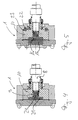
- FIGS. 1 to 5 each show a pump chamber 1 a rotary lobe pump.
- the pump chamber 1 has a housing 2, which is closed by a front housing wall 3 is.
- the front housing wall 3 is with screws 4 on Housing 2 attached and sealed with a seal 5.
- the housing 2 has a front housing wall 3 parallel rear housing wall 6.
- a sealing hub 7 trained bore through which a drive shaft 8 in the Pump chamber 1 is introduced.
- the summarize in the bore 11 of the rotary piston 10 located teeth in a Tooth profile 12, which is located on the end 9.
- the Hole 11 is not continuous.
- An axial extension is in shape on the rotary piston 10 molded on a sleeve 13 which surrounds the drive shaft 8 and which passes through the sealed hub 7.
- the seal 20, which surrounds the hub 7 is thus on the sleeve 13.
- the sleeve 13 abuts with a screwed-in edge 13a Stop 14 on, which surrounds the drive shaft 8 in a ring.
- the stop 14 limits the axial displacement of the Rotary piston 10 in the direction of the rear housing wall 6.
- In the inner wall of the sleeve 13 is screwed into a groove which is a sealing ring (O-ring) 20a. This o-ring 20a seals the sleeve 13 against the drive shaft 8, so that no impurities to the stop 14 forming radially aligned surface can reach.
- the axial displacement of the rotary piston in the direction the front housing wall 3 by magnetic forces caused by two magnets 15 and 16 become.
- the magnet 15 is in the front housing wall 3 installed, while the magnet 16 in the rotary piston 10 is installed behind a thin wall 17.
- the magnets 15 and 16 are poled so that they repel each other.
- the magnet 15 is in a blind hole 18 in the front housing wall 3 used which is closed with a lid 19.
- the repulsive force of the magnets also presses the rotary piston 10 the attached sleeve 13 against the stop 14, so that a Moving the rotary piston on the drive shaft 8 is impossible.
- the axial force of the magnets sufficient to close a mechanical seal.
- a magnet 21 installed in the rotary piston 10 such that it an attractive force on the end 9 of the drive shaft 8 from ferritic material in particular iron.
- the Distance between the end 9 and the magnet 21 is very small and is designed so that the attractive force in the expansion of the rotary piston 10 is easy to overcome.
- FIG 3 a pump chamber 1 is shown, the one Rotary piston 10, which of the magnets 22 in the rear housing wall 6 are installed is tightened. To the attracting force are also in the wings of the Rotary piston 10 magnets 23 installed, the corresponding are polarized in the same direction. The magnets 22 and 23 are arranged concentrically around the drive shaft 8.
- Figure 4 corresponds to that Figure 2 except for the fact that to support the attractive forces of the magnet 21 on the end 9 of the Drive shaft 10 an additional magnet 24 in the end 9 built-in. Both magnets 21 and 24 have the same polarity, so that an attractive force arises.
- the centrally located and the ring-shaped magnets are shaped so that there is no imbalance when the pump is running.
Abstract
Description
Die Erfindung betrifft eine Pumpe insbesondere eine Drehkolbenpumpe mit mindestens einem in einer Pumpenkammer drehenden Rotor, der auf ein in die Pumpenkammer ragendes Ende einer Antriebswelle aufschiebbar ist.The invention relates to a pump, in particular a Rotary lobe pump with at least one in a pump chamber rotating rotor, which protrudes into the pump chamber End of a drive shaft can be pushed.
Drehkolbenpumpen zeichnen sich dadurch aus, daß sie das Fördergut besonders schonend fördern. Außerdem ist ihre Pumpenkammer leicht zugänglich und läßt sich nach der Entnahme der Rotoren effektiv reinigen. Aus diesen Gründen genügen Drehkolbenpumpen hohen hygienischen Anforderungen und werden bevorzugt bei der Produktion von Lebensmitteln, in der pharmazeutischen Verfahrenstechnik oder in der Biotechnologie eingesetzt.Rotary lobe pumps are characterized by the fact that they Conveying goods particularly gently. Besides, hers is Pump chamber easily accessible and can be after the Effectively clean the removal of the rotors. For these reasons Rotary lobe pumps meet high hygienic requirements and are preferred in the production of food, in pharmaceutical process engineering or in Biotechnology used.
Bei den bekannten Drehkolbenpumpen können nach dem Entfernen einer vorderen Gehäusewand die Rotoren von den in die Pumpenkammer ragenden Enden der Antriebswellen abgezogen werden. Um eine exakte Positionierung der Rotoren in Drehrichtung zu gewährleisten, weisen die Enden der Antriebswellen Zahnkränze auf. Die Sicherung der Rotoren gegen achsiale Verschiebung auf der Antriebswelle erfolgt bei bekannten Drehkolbenpumpen außerhalb der Pumpenkammer. Dazu wird eine an den Rotor angebrachte Muffe durch die dichtende Nabe geführt bis der wulstförmige Rand der Muffe gegen einen entsprechenden Ring stößt, der die Antriebswelle außerhalb der Pumpenkammer umgibt. Der wulsförmige Rand und der Ring sind mit einer lösbaren Klammer gegeneinander gehalten.In the known rotary lobe pumps, the Remove a front housing wall from the rotors in the pump chamber projecting ends of the drive shafts subtracted from. For an exact positioning of the rotors to ensure in the direction of rotation, the ends of the Drive shafts sprockets on. Securing the rotors against axial displacement on the drive shaft in known rotary lobe pumps outside the pump chamber. For this purpose, a sleeve attached to the rotor is passed through the sealing hub led up to the beaded edge of the sleeve strikes a corresponding ring that the Surrounds the drive shaft outside the pump chamber. Of the bulbous edge and the ring are detachable Brace held against each other.
Eine Pumpe solcher Ausführung ist in der EP-A-157049 beschrieben, von welcher der Oberbegriff des Anspruchs 1 ausgeht.A pump of this type is described in EP-A-157049, from which the preamble of claim 1 is based.
Nachteilig an der bekannten Halterung ist, daß das Lösen und vor allem das Montieren der Klammer sehr aufwendig ist. So ist ein Werkzeug notwendig um die Schrauben zu lösen und die Klammer, die zwei die Welle und die Muffe umfassende Halbschalen aufweist, zu entfernen. Um eine ausreichend gute Handhabung der Klammern zu ermöglichen muß genügend freier Raum um die Klammern vorhanden sein. Der Abstand zwischen der Pumpenkammer und dem Kupplungsgehäuse muß so groß sein, daß die Hand einer Person dazwischen paßt. Die umständliche Handhabung der Klammer macht die Wartungs- und Reinigungsarbeiten an der Pumpe verhältnismäßig aufwendig.A disadvantage of the known holder is that the release and especially the assembly of the bracket is very complex. So a tool is necessary to loosen the screws and the bracket, the two encompassing the shaft and the sleeve Has half shells to remove. To be sufficient To allow good handling of the brackets must be sufficient there should be free space around the brackets. The distance between the pump chamber and the clutch housing large that a person’s hand fits in between. The cumbersome handling of the clip makes the maintenance and Cleaning work on the pump is relatively complex.
Aufgabe der Erfindung ist es, eine Pumpe insbesondere eine Drehkolbenpumpe zu schaffen, deren mindestens einer Rotor auf einfache Weise von der Antriebswelle abnehmbar ist und deren Pumpenkammer einfach und gründlich gereinigt werden kann.The object of the invention is to provide a pump in particular To create a rotary lobe pump whose at least one rotor is easily removable from the drive shaft and whose pump chamber can be cleaned easily and thoroughly can.
Die Aufgabe wird erfindungsgemäß durch eine Pumpe nach dem Anspruch 1 gelöst.The object is achieved by a pump according to the Claim 1 solved.
Vorteilhafte Ausführungsformen der erfindungsgemäßen Pumpe sind in den Unteransprüchen aufgeführt.Advantageous embodiments of the pump according to the invention are listed in the subclaims.
Wesentlicher Vorteil der erfindungsgemäßen Pumpe und den mit Hilfe der von Magneten erzeugten magnetischen Kraft auf der Antriebswelle befestigten Rotoren ist, daß die Rotoren nach dem Entfernen der vorderen Gehäusewand mit wenigen Handgriffen von den in die das Rotorgehäuse bildende Pumpenkammer ragenden Enden der Antriebswelle abgezogen werden können, ohne daß zusätzliche Werkzeuge nötig sind. In einer besonderen Ausführungsform kann der Rotor von der Antriebswelle gezogen werden, indem die vordere Gehäusewand mit dem darin befindlichen Magneten umgedreht wird, so daß der Magnet den Rotor anzieht. Die Montage eines Rotors auf einer Antriebswelle ist so komfortabel, daß sie auch maschinell durchgeführt werden kann.Significant advantage of the pump according to the invention and the with the help of the magnetic force generated by magnets The rotors attached to the drive shaft is that the rotors after removing the front housing wall with a few Handles from the one that forms the rotor housing Pump chamber protruding ends of the drive shaft deducted can be made without the need for additional tools. In a special embodiment, the rotor of the Drive shaft pulled by the front housing wall with the magnet inside is turned over so that the magnet attracts the rotor. The assembly of a rotor a drive shaft is so comfortable that it too can be done mechanically.
Die erfindungsgemäße Halterung durch die Magnete trägt außerdem dazu bei, daß die Pumpe besonders kompakt gebaut werden kann, da kein gesonderter Raum für die Handhabung der Verbindung zwischen Rotor und Antriebswelle nötig ist. Die magnetischen Kräfte können dabei von Permanentmagneten oder von Elektromagneten erzeugt werden. Der Einsatz von Permanentmagneten hat den Vorteil, daß große magnetische Kräfte auch ohne eine zusätzliche elektrische Versorgung zur Verfügung stehen. Außerdem können die Permanentmagneten an beliebigen Stellen in die Rotoren oder die Gehäuseteile eingebaut werden. Elektromagneten haben dagegen den Vorteil, daß die magnetische Kraft nach Bedarf ein- und ausschaltbar ist. Das Entfernen der Rotoren bei ausgeschalteten Magneten ist besonders einfach.The holder according to the invention carries through the magnets also help to make the pump particularly compact can be because there is no separate space for handling the connection between the rotor and drive shaft is necessary. The magnetic forces can be from permanent magnets or generated by electromagnets. The use of Permanent magnets have the advantage of being large magnetic Forces even without an additional electrical supply be available. In addition, the permanent magnets anywhere in the rotors or the housing parts to be built in. Electromagnets have the Advantage that the magnetic force on and off as required can be switched off. Removing the rotors at switched off magnet is particularly simple.
Die magnetische Halterung hat den Vorteil, daß sie bei allen Pumpentypen, die einen auf einer Antriebswelle befestigten Rotor aufweisen, anwendbar ist. Speziell bei Drehkolbenpumpen ist eine besonders vorteilhafte achsiale Halterung der Rotoren (Drehkolben) auf der Antriebswelle möglich, wenn der Rotor oder ein mit dem Rotor verbundenes Teil insbesondere eine Muffe von der magnetischen Kraft gegen einen Anschlag gedrückt wird. Der Anschlag ist dabei vorteilhafterweise eine Kante oder ein Ring der die Antriebswelle umgibt. Durch die einfache Handhabung des vorderen Gehäusedeckels und der Rotoren wird eine komfortable Wartung und Reinigung der Pumpenkammer einer Drehkolbenpumpe mit wenigen Handgriffen ermöglicht. Außerdem hat die erfindungsgemäße Drehkolbenpumpe den Vorteil, daß in der Pumpenkammer außer in der dichtenden Nabe keine Spalten sind, in denen sich Fördergut absetzen und zur Brutstätte von Keimen werden kann.The magnetic holder has the advantage that it all pump types, one on a drive shaft have attached rotor, is applicable. Especially at Rotary lobe pumps are a particularly advantageous axial one Bracket of the rotors (rotary pistons) on the drive shaft possible if the rotor or one connected to the rotor Part in particular a sleeve from the magnetic force is pressed against a stop. The attack is there advantageously an edge or a ring of the Surrounds the drive shaft. The easy handling of the front housing cover and the rotors becomes one convenient maintenance and cleaning of the pump chamber one Rotary lobe pump made possible in a few simple steps. Furthermore the rotary lobe pump according to the invention has the advantage that none in the pump chamber except in the sealing hub There are gaps in which goods to be conveyed settle and to Can be a breeding ground for germs.
Es ist vorteilhaft, in die vordere Gehäusewand der Pumpenkammer Magnete einzusetzen, die abstoßende Kräfte auf zentral unter der zur vorderen Gehäusewand gerichtete Oberfläche der Rotoren ausüben. Nach dem Entfernen der Gehäusewand sind die Rotoren leicht entnehmbar, da keine haltenden Kräfte mehr wirken.It is advantageous in the front housing wall Pump chamber use magnets that repel forces centrally below the one facing the front housing wall Apply the surface of the rotors. After removing the The rotors are easy to remove because there are none holding forces work more.
Um die Bildung von Wirbelströmen zu vermeiden ist es vorteilhaft, einen Magneten im Rotor anzuordnen, der eine anziehende Kraft auf das rotierende vordere Ende der Antriebswelle ausübt. Um die anziehende Kraft zwischen dem Ende der Antriebswelle und dem Rotor zu erhöhen ist es vorteilhaft, in das Ende der Antriebswelle ebenfalls einen Magneten einzubauen, der dem Magneten im Rotor mit dem entsprechenden Gegenpol gegenüberliegt. In einer besonderen Ausführungsform der Drehkolbenpumpe ist ein Magnet ringförmig um das Ende der an den Rotor geformten Muffe angeordnet. Dieser Magnet wirkt mit einer anziehenden Kraft auf einen um die Welle verlaufenden ringförmigen Vorsprung oder einen ringförmig angeordneten Magnet.It is to avoid the formation of eddy currents advantageous to arrange a magnet in the rotor, the one attractive force on the rotating front end of the Drives shaft. To the attractive force between the It is the end of the drive shaft and the rotor to raise advantageous, also in the end of the drive shaft Install the magnet that matches the magnet in the rotor with the corresponding opposite pole is opposite. In a special one The embodiment of the rotary lobe pump is a magnet ring-shaped around the end of the sleeve formed on the rotor arranged. This magnet works with an attractive force on an annular projection running around the shaft or a ring-shaped magnet.
In einer weiteren Ausführungsform sind Magneten in die zur hinteren Gehäusewand der Pumpenkammer gerichteten Flächen des Rotors eingebaut. Um die anziehende Kraft zu verstärken ist es vorteilhaft, auch in die hintere Gehäusewand Magnete einzubauen, die insbesondere zu einem Ring zusammengesetzt sind. Dadurch wird eine gleichmäßige anziehende Kraft erreicht.In a further embodiment, magnets are in the rear housing wall of the pump chamber facing surfaces of the rotor installed. To increase the attractive force it is advantageous to also use magnets in the rear case wall to install, which in particular put together into a ring are. This creates an even attractive force reached.
Ausführungsbeispiele der erfindungsgemäßen Pumpe sind in den Zeichnungen 1 bis 6 dargestellt und werden im folgenden näher beschrieben.Embodiments of the pump according to the invention are in the drawings 1 to 6 and are shown below described in more detail.
Es zeigen:
- Figur 1
- eine Seitenansicht durch eine Pumpenkammer bei der die Magnete in der vorderen Gehäusewand und dem Drehkolben eingebracht sind,
- Figur 2
- eine Pumpenkammer mit einem Magnet der auf die Antriebswelle wirkt,
Figur 3- eine Pumpenkammer mit Magneten, die in die hintere Gehäusewand und die Flügel des Drehkolbens eingebaut sind,
Figur 4- eine Pumpenkammer mit Magneten, die in den Drehkolben und das Ende der Antriebswelle eingebaut sind
Figur 5- eine Pumpenkammer mit abstoßend wirkenden und anziewhend wirkenden Magneten.
- Figure 1
- a side view through a pump chamber in which the magnets are introduced in the front housing wall and the rotary piston,
- Figure 2
- a pump chamber with a magnet that acts on the drive shaft,
- Figure 3
- a pump chamber with magnets built into the rear housing wall and the wings of the rotary lobe,
- Figure 4
- a pump chamber with magnets built into the rotary lobe and the end of the drive shaft
- Figure 5
- a pump chamber with repulsive and attractive magnets.
Die Figuren 1 bis 5 zeigen jeweils eine Pumpenkammer 1
einer Drehkolbenpumpe. Die Pumpenkammer 1 weist ein Gehäuse
2 auf, das von einer vorderen Gehäusewand 3 verschlossen
ist. Die vordere Gehäusewand 3 ist mit Schrauben 4 am
Gehäuse 2 befestigt und mit einer Dichtung 5 abgedichtet.
Das Gehäuse 2 weist eine zur vorderen Gehäusewand 3
parallele hintere Gehäusewand 6 auf. In der hinteren
Gehäusewand 6 befindet sich eine als dichtende Nabe 7
ausgebildete Bohrung, durch die eine Antriebswelle 8 in die
Pumpenkammer 1 eingeführt ist. Auf das in die Pumpenkammer
1 hineinragende Ende 9 der Antriebswelle 8 ist ein Rotor in
Form eines Drehkolbens 10 aufschiebbar. Dabei fassen die in
der Bohrung 11 des Drehkolbens 10 befindlichen Zähne in ein
Zahnprofil 12, das sich auf dem Ende 9 befindet. Die
Bohrung 11 ist nicht durchgängig.FIGS. 1 to 5 each show a pump chamber 1
a rotary lobe pump. The pump chamber 1 has a housing
2, which is closed by a
An den Drehkolben 10 ist eine achsiale Verlängerung in Form
einer Muffe 13 angeformt, welche die Antriebswelle 8 umgibt
und die die gedichtete Nabe 7 durchfaßt. Die Dichtung 20,
welche die Nabe 7 umgibt, liegt somit an der Muffe 13 an.
Die Muffe 13 stößt mit einem eingedrehten Rand 13a an einen
Anschlag 14 an, der die Antriebswelle 8 ringförmig umgibt.
Der Anschlag 14 begrenzt das achsiale Verschieben des
Drehkolbens 10 in Richtung der hinteren Gehäusewand 6. In
die Innenwandung der Muffe 13 ist eine Nut eingedreht, in
der ein Dichtungsring (O-Ring) 20a einliegt. Dieser O-Ring
20a dichtet die Muffe 13 gegen die Antriebswelle 8, so daß
keine Verunreingungen zu der den Anschlag 14 bildendenden
radial ausgerichteten Fläche gelangen kann.An axial extension is in shape on the rotary piston 10
molded on a
Die aus der Pumpenkammer 1 herausragende und gegen das
Gehäuse 2 abgedichtete Muffe 13 bewirkt, daß in der
Pumpenkammer 1 keine Spalten zwischen der Antriebswelle 8
und dem Drehkolben 10 entstehen, in die Fördergut gelangen
könnte. Da der Drehkolben 10 auf seiner Vorderseite eine
geschlossene Fläche aufweist, ist die Antriebswelle gegen
das Fördermedium vollständig abgedichtet.The protruding from the pump chamber 1 and against that
Housing 2 sealed
Bei dem in Figur 1 dargestellten Ausführungsbeispiel wird
die achsiale Verschiebung des Drehkolbens in die Richtung
der vorderen Gehäusewand 3 durch magnetische Kräfte
bewirkt, die von zwei Magneten 15 und 16 hervorgerufen
werden. Dazu ist der Magnet 15 in der vorderen Gehäusewand
3 eingebaut, während sich der Magnet 16 im Drehkolben 10
hinter einer dünnen Wand 17 eingebaut ist. Die Magneten 15
und 16 sind so gepolt, daß sie sich abstoßen. Der Magnet 15
ist in einer Sackbohrung 18 in der vorderen Gehäusewand 3
eingesetzt die mit einem Deckel 19 verschlossen ist. Die
abstoßende Kraft der Magneten drückt den Drehkolben 10 mit
der angebrachten Muffe 13 gegen den Anschlag 14, so daß ein
Verschieben des Drehkolbens auf der Antriebswelle 8
unmöglich ist. Dabei ist die axiale Kraft der Magneten
ausreichend, um eine mechanische Dichtung zu schließen.In the embodiment shown in Figure 1
the axial displacement of the rotary piston in the direction
the
Bei dem in Figur 2 dargestellten Ausführungsbeispiel ist
ein Magnet 21 derart in den Drehkolben 10 eingebaut, daß er
eine anziehende Kraft auf das Ende 9 der Antriebswelle 8
aus ferritschem Material insbesondere Eisen ausübt. Der
Abstand zwischen dem Ende 9 dem Magnet 21 ist sehr gering
und wird so ausgelegt, daß die anziehende Kraft beim Ausbau
des Drehkolbens 10 gut zu überwinden ist.In the embodiment shown in Figure 2 is
a magnet 21 installed in the rotary piston 10 such that it
an attractive force on the end 9 of the
In Figur 3 ist eine Pumpenkammer 1 gezeigt, die einen
Drehkolben 10 aufweist, der von Magneten 22 die in die
hintere Gehäusewand 6 eingebaut sind angezogen wird. Um die
anziehende Kraft zu verstärken sind auch in die Flügel des
Drehkolbens 10 Magnete 23 eingebaut, die entsprechend
gleichgerichtet gepolt sind. Die Magnete 22 und 23 sind
konzentrisch um die Antriebswelle 8 angeordnet.In Figure 3, a pump chamber 1 is shown, the one
Rotary piston 10, which of the
Das Ausführungsbeispiel nach Figur 4 entspricht dem nach
Figur 2 bis auf die Tatsache, daß zur Unterstützung der
anziehenden Kräfte des Magneten 21 auf das Ende 9 der
Antriebswelle 10 ein zusätzlicher Magnet 24 in das Ende 9
eingebaut. Beide Magneten 21 und 24 sind gleichgepolt, so
daß eine anziehende Kraft entsteht.The embodiment of Figure 4 corresponds to that
Figure 2 except for the fact that to support the
attractive forces of the magnet 21 on the end 9 of the
Drive shaft 10 an
Bei dem Ausführungsbeispiel einer Drehkolbenpumpe nach
Figur 5 ist die abstoßende Wirkung der Magnete 15 und 16
(vergleiche Figur 1) mit der anziehenden Wirkung der
Magnete 22 und 23 (vergleiche Figur 3) vereint. Durch die
Kombination mehrerer Magnete besteht die Möglichkeit, die
Kraft der einzelnen Magnete geringer zu bemessen um somit
der Erzeugung von Wirbelströmen entgegenzuwirken und um die
Erwärmung des Drehkolbens und der Pumpenkammer zu
homogenisieren.In the embodiment of a rotary lobe pump according to
Figure 5 is the repulsive effect of
Die zentral angeordneten und die ringförmigen Magneten sind so geformt, daß keine Unwucht beim Lauf der Pumpe auftritt.The centrally located and the ring-shaped magnets are shaped so that there is no imbalance when the pump is running.
Claims (11)
- A pump, specifically a rotary lobe pump, having at least one rotor (10) revolving in a pumping chamber, said rotor being slidably placed on the end (9) of a drive shaft (8) projecting into said pumping chamber (1), characterised in that said rotor (10), or a part connected thereto, is retained in its axial position by a maqnetic force.
- A pump as set forth in claim 1, characterised in that said magnetic force presses the rotor (10) or the part connected thereto against a stop (14) which prevents an axial displacement of the rotor (10) an the drive shaft (8).
- A pump as set forth in any of claim 1 or 2, characterised in that said magnetic force is produced by at least one permanent magnet acting upon a ferritic material or an another magnet.
- A pump as set forth in any of the preceding claims, characterised in that said magnetic force is produced by at least one electric magnet acting upon a ferritic material or an another magnet.
- A pump as set forth in any of the preceding claims, characterised in that there is provided with a sleeve (13) at the rotor (10), said sleeve surrounding said drive shaft, wherein there is provided a seal, especially an O-ring seal (20a) located between the sleeve and the drive shaft (8).
- A pump as set forth in any of the preceding claims, characterised in that the pump is a rotary lobe pump having at least two rotors (10) in the form of rotary lobe pistons.
- A pump as set forth in any of the preceding claims, characterised in that there is provided one magnet (15) in the front housing wall (3) and one magnet (16) in the front face of the rotary lobe piston facing said front housing wall (3), the polarity of said magnets (15, 16) being selected such that the magnets repel each other.
- A pump as set forth in any of the preceding claims, characterised in that further comprising a magnet (21) in the rotary lobe piston (10) which exerts an attracting force an a front end (9) of the drive shaft (8).
- A pump as set forth in any of the preceding claims, characterised in that there are provided magnets (23) in the lobes of the rotary lobe piston (10) to exert an attracting force an the rear housing wall (6).
- A pump as set forth in claim 9, characterised in that there are provided magnets (22) in the rear housing wall (6), their polarity being selected such that they exert an attracting force on the magnets (23) in the lobes.
- A pump as set forth in any of the preceding claims, characterised in that there are provided one magnet (21) in the rotary lobe piston (10) and one magnet (24) in the front end (9) of the drive shaft (8), the polarity of said magnets (21, 24) being selected such that these magnets attract each other.
Applications Claiming Priority (2)
| Application Number | Priority Date | Filing Date | Title |
|---|---|---|---|
| DE19613148 | 1996-04-03 | ||
| DE19613148A DE19613148A1 (en) | 1996-04-03 | 1996-04-03 | Rotary lobe pump with magnetic rotor holder |
Publications (2)
| Publication Number | Publication Date |
|---|---|
| EP0799998A1 EP0799998A1 (en) | 1997-10-08 |
| EP0799998B1 true EP0799998B1 (en) | 1999-04-14 |
Family
ID=7790252
Family Applications (1)
| Application Number | Title | Priority Date | Filing Date |
|---|---|---|---|
| EP97104154A Expired - Lifetime EP0799998B1 (en) | 1996-04-03 | 1997-03-12 | Rotary piston pump with magnetic retaining means |
Country Status (4)
| Country | Link |
|---|---|
| US (1) | US5957677A (en) |
| EP (1) | EP0799998B1 (en) |
| AT (1) | ATE178976T1 (en) |
| DE (2) | DE19613148A1 (en) |
Families Citing this family (7)
| Publication number | Priority date | Publication date | Assignee | Title |
|---|---|---|---|---|
| DE19812976C2 (en) * | 1998-03-24 | 2000-05-04 | Siemens Ag | Liquid ring compressor |
| US6244842B1 (en) * | 1999-11-09 | 2001-06-12 | James B. Tieben | Pump |
| CN1120286C (en) * | 1999-08-27 | 2003-09-03 | 詹姆斯·B·蒂本 | Pump |
| DE10024020A1 (en) * | 2000-05-16 | 2001-11-22 | Schlafhorst & Co W | Open-end spinning rotor |
| JP5894684B2 (en) | 2012-02-17 | 2016-03-30 | ネッチュ−モーノプンペン ゲーエムベーハー | Rotary piston pump |
| US9500208B2 (en) * | 2014-04-25 | 2016-11-22 | Apple Inc. | Magnetic preloading of joints |
| CN111946613B (en) * | 2020-08-25 | 2022-02-22 | 扬州大学 | Design method of micro disc pump based on laminar boundary layer and rotating magnetic field |
Family Cites Families (16)
| Publication number | Priority date | Publication date | Assignee | Title |
|---|---|---|---|---|
| DE1060482B (en) * | 1958-06-28 | 1959-07-02 | Gossen & Co Gmbh P | Adjustable inner bearing for core magnetic measuring mechanisms |
| US3080170A (en) * | 1959-01-02 | 1963-03-05 | Magnetic Seal Corp | Seal providing for substantial axial movement |
| DE2056661C3 (en) * | 1970-11-18 | 1975-03-27 | Eisenwerke Kaiserslautern Gmbh, 6750 Kaiserslautern | Displacement blades for a rotary lobe pump for pumping viscous, possibly inhomogeneous, corrosive media |
| DE2206237A1 (en) * | 1972-02-10 | 1973-08-23 | Skf Kugellagerfabriken Gmbh | Shaft bearing - with shell in pole plate to support ball and shaft |
| DE2337226A1 (en) * | 1973-07-21 | 1975-02-06 | Maschf Augsburg Nuernberg Ag | VACUUM PUMP WITH A RUNNER MOUNTED INSIDE THEIR HOUSING |
| GB8333929D0 (en) * | 1983-12-20 | 1984-02-01 | Ssp Pumps | Rotary pumps |
| DE8815196U1 (en) * | 1988-12-07 | 1989-02-16 | Lewitz, Reinwald, 3100 Celle, De | |
| NL9000785A (en) * | 1990-04-03 | 1991-11-01 | Boer B V De | Displacement pump. |
| NL9001875A (en) * | 1990-07-17 | 1992-02-17 | Bombas Stork S A | LOBBY ROTOR PUMP. |
| DE4024067A1 (en) * | 1990-07-28 | 1992-01-30 | Friedhelm Schneider | Geared pump for high viscosity liq. - has gearwheels mounted on sealed tapered roller bearings |
| JP2983325B2 (en) * | 1991-04-26 | 1999-11-29 | 株式会社日本自動車部品総合研究所 | Scroll compressor |
| US5129795A (en) * | 1991-05-31 | 1992-07-14 | Powerdyne Corporation | Motor driven pump |
| US5350283A (en) * | 1991-12-04 | 1994-09-27 | Ntn Corporation | Clean pump |
| DE4224736A1 (en) * | 1992-07-27 | 1994-02-03 | Luk Fahrzeug Hydraulik | Hydraulic machine with rotor and connected shaft - has ball positively connecting both parts to transfer torque and prevent axial relative displacement. |
| US5391068A (en) * | 1994-02-15 | 1995-02-21 | Eaton Corporation | Gear pump |
| DE4410656A1 (en) * | 1994-03-26 | 1995-09-28 | Balzers Pfeiffer Gmbh | Friction pump |
-
1996
- 1996-04-03 DE DE19613148A patent/DE19613148A1/en not_active Withdrawn
-
1997
- 1997-03-12 DE DE59700129T patent/DE59700129D1/en not_active Expired - Lifetime
- 1997-03-12 EP EP97104154A patent/EP0799998B1/en not_active Expired - Lifetime
- 1997-03-12 AT AT97104154T patent/ATE178976T1/en not_active IP Right Cessation
- 1997-03-31 US US08/829,932 patent/US5957677A/en not_active Expired - Fee Related
Also Published As
| Publication number | Publication date |
|---|---|
| EP0799998A1 (en) | 1997-10-08 |
| DE19613148A1 (en) | 1997-10-09 |
| US5957677A (en) | 1999-09-28 |
| DE59700129D1 (en) | 1999-05-20 |
| ATE178976T1 (en) | 1999-04-15 |
Similar Documents
| Publication | Publication Date | Title |
|---|---|---|
| DE2337226A1 (en) | VACUUM PUMP WITH A RUNNER MOUNTED INSIDE THEIR HOUSING | |
| DE69828418T2 (en) | VALVE AND OSCILLATOR FOR PRODUCING A PRESSURE CURVE | |
| EP0799998B1 (en) | Rotary piston pump with magnetic retaining means | |
| EP0965163A1 (en) | Electronically switched d.c. motor | |
| EP3289221A1 (en) | Fluid pump | |
| DE3204534C2 (en) | Electromagnetically operated diaphragm pump | |
| DE3220614C2 (en) | ||
| DE60313493T2 (en) | VACUUM PUMP | |
| EP2016287A1 (en) | Rotary piston machine | |
| DE20102723U1 (en) | vacuum cleaner | |
| DE29909293U1 (en) | Electromagnetically operated motor | |
| DE3626994C1 (en) | Shooting device on a core shooter | |
| DE1938430B2 (en) | Electric double diaphragm pump, e.g. as an air pump for ventilating aquariums | |
| EP0918932B1 (en) | Electromotor/pump assembly | |
| EP3299627B1 (en) | Feed pump | |
| DE4110488A1 (en) | Rotating magnetic coupling for flow valve - has filter between coupling magnets to prevent particles from entering housing | |
| DE19755537A1 (en) | Transport safety mechanism for assembled and justified motor kit brushless DC motor, e.g for washing machines | |
| DE514444C (en) | Device for attaching a rotatable polishing agent to a vacuum cleaner | |
| EP3266343A1 (en) | Brush unit for a brush roller for an abrasive blasting installation | |
| DE4123551A1 (en) | OVERLAP ROTATION PUMP | |
| DE444482C (en) | Machine set consisting of an electric motor and multi-stage air delivery device, especially for electric hand vacuum cleaners | |
| DE3500465C2 (en) | ||
| DE60109577T2 (en) | Tangential ventilation device | |
| DE19509134A1 (en) | Stator mounting for a canned motor | |
| EP0844723A2 (en) | Electric motor driven pump |
Legal Events
| Date | Code | Title | Description |
|---|---|---|---|
| PUAI | Public reference made under article 153(3) epc to a published international application that has entered the european phase |
Free format text: ORIGINAL CODE: 0009012 |
|
| AK | Designated contracting states |
Kind code of ref document: A1 Designated state(s): AT BE CH DE DK ES FR GB IE IT LI NL SE |
|
| 17P | Request for examination filed |
Effective date: 19971002 |
|
| GRAG | Despatch of communication of intention to grant |
Free format text: ORIGINAL CODE: EPIDOS AGRA |
|
| 17Q | First examination report despatched |
Effective date: 19981118 |
|
| GRAG | Despatch of communication of intention to grant |
Free format text: ORIGINAL CODE: EPIDOS AGRA |
|
| GRAH | Despatch of communication of intention to grant a patent |
Free format text: ORIGINAL CODE: EPIDOS IGRA |
|
| GRAH | Despatch of communication of intention to grant a patent |
Free format text: ORIGINAL CODE: EPIDOS IGRA |
|
| GRAA | (expected) grant |
Free format text: ORIGINAL CODE: 0009210 |
|
| AK | Designated contracting states |
Kind code of ref document: B1 Designated state(s): AT BE CH DE DK ES FR GB IE IT LI NL SE |
|
| PG25 | Lapsed in a contracting state [announced via postgrant information from national office to epo] |
Ref country code: SE Free format text: THE PATENT HAS BEEN ANNULLED BY A DECISION OF A NATIONAL AUTHORITY Effective date: 19990414 Ref country code: NL Free format text: LAPSE BECAUSE OF FAILURE TO SUBMIT A TRANSLATION OF THE DESCRIPTION OR TO PAY THE FEE WITHIN THE PRESCRIBED TIME-LIMIT Effective date: 19990414 Ref country code: IT Free format text: LAPSE BECAUSE OF FAILURE TO SUBMIT A TRANSLATION OF THE DESCRIPTION OR TO PAY THE FEE WITHIN THE PRE;WARNING: LAPSES OF ITALIAN PATENTS WITH EFFECTIVE DATE BEFORE 2007 MAY HAVE OCCURRED AT ANY TIME BEFORE 2007. THE CORRECT EFFECTIVE DATE MAY BE DIFFERENT FROM THE ONE RECORDED.SCRIBED TIME-LIMIT Effective date: 19990414 Ref country code: GB Free format text: LAPSE BECAUSE OF NON-PAYMENT OF DUE FEES Effective date: 19990414 Ref country code: FR Free format text: LAPSE BECAUSE OF FAILURE TO SUBMIT A TRANSLATION OF THE DESCRIPTION OR TO PAY THE FEE WITHIN THE PRESCRIBED TIME-LIMIT Effective date: 19990414 Ref country code: ES Free format text: THE PATENT HAS BEEN ANNULLED BY A DECISION OF A NATIONAL AUTHORITY Effective date: 19990414 |
|
| REF | Corresponds to: |
Ref document number: 178976 Country of ref document: AT Date of ref document: 19990415 Kind code of ref document: T |
|
| REG | Reference to a national code |
Ref country code: CH Ref legal event code: EP |
|
| REG | Reference to a national code |
Ref country code: IE Ref legal event code: FG4D Free format text: GERMAN |
|
| REF | Corresponds to: |
Ref document number: 59700129 Country of ref document: DE Date of ref document: 19990520 |
|
| PG25 | Lapsed in a contracting state [announced via postgrant information from national office to epo] |
Ref country code: DK Free format text: LAPSE BECAUSE OF FAILURE TO SUBMIT A TRANSLATION OF THE DESCRIPTION OR TO PAY THE FEE WITHIN THE PRESCRIBED TIME-LIMIT Effective date: 19990714 |
|
| NLV1 | Nl: lapsed or annulled due to failure to fulfill the requirements of art. 29p and 29m of the patents act | ||
| EN | Fr: translation not filed | ||
| GBV | Gb: ep patent (uk) treated as always having been void in accordance with gb section 77(7)/1977 [no translation filed] |
Effective date: 19990414 |
|
| PG25 | Lapsed in a contracting state [announced via postgrant information from national office to epo] |
Ref country code: IE Free format text: LAPSE BECAUSE OF NON-PAYMENT OF DUE FEES Effective date: 19991206 |
|
| REG | Reference to a national code |
Ref country code: IE Ref legal event code: FD4D |
|
| PLBE | No opposition filed within time limit |
Free format text: ORIGINAL CODE: 0009261 |
|
| STAA | Information on the status of an ep patent application or granted ep patent |
Free format text: STATUS: NO OPPOSITION FILED WITHIN TIME LIMIT |
|
| PG25 | Lapsed in a contracting state [announced via postgrant information from national office to epo] |
Ref country code: AT Free format text: LAPSE BECAUSE OF NON-PAYMENT OF DUE FEES Effective date: 20000312 |
|
| PG25 | Lapsed in a contracting state [announced via postgrant information from national office to epo] |
Ref country code: BE Free format text: LAPSE BECAUSE OF NON-PAYMENT OF DUE FEES Effective date: 20000331 |
|
| 26N | No opposition filed | ||
| BERE | Be: lapsed |
Owner name: ALFA LAVAL FLOW G.M.B.H. Effective date: 20000331 |
|
| PG25 | Lapsed in a contracting state [announced via postgrant information from national office to epo] |
Ref country code: LI Free format text: LAPSE BECAUSE OF NON-PAYMENT OF DUE FEES Effective date: 20010331 Ref country code: CH Free format text: LAPSE BECAUSE OF NON-PAYMENT OF DUE FEES Effective date: 20010331 |
|
| REG | Reference to a national code |
Ref country code: CH Ref legal event code: PL |
|
| PGFP | Annual fee paid to national office [announced via postgrant information from national office to epo] |
Ref country code: DE Payment date: 20100318 Year of fee payment: 14 |
|
| PG25 | Lapsed in a contracting state [announced via postgrant information from national office to epo] |
Ref country code: DE Free format text: LAPSE BECAUSE OF NON-PAYMENT OF DUE FEES Effective date: 20111001 |
|
| REG | Reference to a national code |
Ref country code: DE Ref legal event code: R119 Ref document number: 59700129 Country of ref document: DE Effective date: 20111001 |