EP0799561B1 - Cutter assembly for mowing apparatus - Google Patents
Cutter assembly for mowing apparatus Download PDFInfo
- Publication number
- EP0799561B1 EP0799561B1 EP96115201A EP96115201A EP0799561B1 EP 0799561 B1 EP0799561 B1 EP 0799561B1 EP 96115201 A EP96115201 A EP 96115201A EP 96115201 A EP96115201 A EP 96115201A EP 0799561 B1 EP0799561 B1 EP 0799561B1
- Authority
- EP
- European Patent Office
- Prior art keywords
- hold
- down means
- cutter assembly
- knife
- knife section
- Prior art date
- Legal status (The legal status is an assumption and is not a legal conclusion. Google has not performed a legal analysis and makes no representation as to the accuracy of the status listed.)
- Expired - Lifetime
Links
- 238000005520 cutting process Methods 0.000 claims description 12
- 238000006073 displacement reaction Methods 0.000 claims description 2
- 239000000463 material Substances 0.000 description 7
- 239000004952 Polyamide Substances 0.000 description 3
- 229920002647 polyamide Polymers 0.000 description 3
- 229910000831 Steel Inorganic materials 0.000 description 2
- 230000000712 assembly Effects 0.000 description 2
- 238000000429 assembly Methods 0.000 description 2
- 230000000670 limiting effect Effects 0.000 description 2
- 239000010959 steel Substances 0.000 description 2
- 230000006835 compression Effects 0.000 description 1
- 238000007906 compression Methods 0.000 description 1
- 238000004519 manufacturing process Methods 0.000 description 1
- 239000010813 municipal solid waste Substances 0.000 description 1
- 229920001778 nylon Polymers 0.000 description 1
- 239000007787 solid Substances 0.000 description 1
- 125000006850 spacer group Chemical group 0.000 description 1
Images



Classifications
-
- A—HUMAN NECESSITIES
- A01—AGRICULTURE; FORESTRY; ANIMAL HUSBANDRY; HUNTING; TRAPPING; FISHING
- A01D—HARVESTING; MOWING
- A01D34/00—Mowers; Mowing apparatus of harvesters
- A01D34/01—Mowers; Mowing apparatus of harvesters characterised by features relating to the type of cutting apparatus
- A01D34/02—Mowers; Mowing apparatus of harvesters characterised by features relating to the type of cutting apparatus having reciprocating cutters
- A01D34/13—Cutting apparatus
- A01D34/17—Holding-down devices for the knife
Definitions
- the invention relates to a cutter assembly for a mowing apparatus according to the preamble of claim 1. More particularly, the invention pertains to an apparatus having at least two guards where each guard has a guard body and a tine secured to the guard body. Between the guard body and the tine is a knife slot in which is positioned a knife section. The knife section reciprocates as the cutter assembly moves during the cutting operation. A means to hold down the knife section during operation is provided.
- US-A- 4 519 192 teaches a hold-down bar having a center section that is formed downwards in the direction of the knife sectionsin order to hold the knife sections down.
- This hold-down bar is not adjustable during the life of the sickle guard. That is why the holding down function will gradually diminish.
- US-A-5 487 259 discloses prior art cutter assemblies.
- extra rigid hold-down arms are mounted on the cutter bar.
- a centre web of each hold-down arm is extending forwardly between the guards and carries hold-down elements.
- Each hold-down element is screwed into the centre web and is cooperating with the knife section to hold the latter down.
- GB-A-1155464 cast or forged hold-down clips are arranged at spaced intervals along a mounting member. Each clip is T-shaped in plan view and is fixed by means of two guard mounting screws to the cutter bar. A forwardly extending portion has an undersurface arranged to come into sliding contact with the upper faces of the knife sections. The clips and their assembly and possible adjustment perpendicular to the upper faces of the knife sections are costly and heavy.
- each hold-down clip into a mounting flange and a hold-down arm which is linked thereto at and so as to be capable of being raised and lowered.
- an adjustment screw inserted into the rearward end of the hold-down arm and engaging at against the cutter bar, there is a minimum distance between a lower guide face of the hold-down arm and the knife sections.
- the holding down of the knife sections has the purpose of achieving and maintaining optimum cutting action between the knife section cutting edges and the cutting edges of the guards which cooperate therewith. If there is too great a distance between these cutting edges transversely to the stroke direction of the knife sections, then the growth and material to be cut will not be cut cleanly, but rather will be squashed or knocked off. This can lead to damage of the mowing apparatus in use and increase the drive energy requirements. Furthermore, if the upward movement of the knife sections is not restrained during use, these knife sections could strike against the tines of the guards during their reciprocating stroke movement. This could lead to breakage of the guards and do damage to the knife sections.
- the hold-down member of the present invention can be used with advantage independently of the type of the particular guard and independently of the type of knife sections used. Thus, knife sections with serrated facets can be used without any difficulty.
- special, bulky hold-down means fixed to the cutter bar are superflous.
- the hold-down member of the present invention also allows a considerable reduction in the weight carried by the cutter bar in total and ensures a better flow of crops. Since the hold-down member is adjustable relative to the upper trashbar in the direction towards and away from the knife sections, the knife section cutting edges are always brought into the optimum position in relation to the corresponding cutting edges on the guards.
- the hold-down member has an external thread and fits into a threaded hole provided in the upper trashbar. This results in a particularly simple and easy mounting of the hold-down member in the upper trashbar. Also, eventual replacement of hold-down members can be effected with little cost.
- the hold-down member comprises a ball member biased into contact with the upper face of the knife sections by spring means.
- This type of hold-down member may further include stop means for limiting displacement of the ball member from the hold-down member. This reduces wear on the hold-down member and on the knife sections.
- the hold-down member comprises a stud screw-like member screwed into the threaded hole of the upper trashbar to hold down the knife section.
- the sickle guard 10 comprises two guards 12 and 14 connected rigidly together by a connecting web 16 to form a one-piece multiple (in this case, double) sickle guard.
- the connecting web includes a forward connecting web 18, also known as a lower trashbar, in front of a knife back 30, and a rearward connecting web 20 behind the knife back.
- Each guard 12, 14 may carry an outer trashbar as disclosed in US-A-5 487 259.
- Each guard 12, 14 comprises a guard body 22 and a tine 24 fixed to the guard body 22 at the front end of the guard body 22 in the mowing direction of the cutter assembly (right-hand side as shown in FIGS. 1 and 2).
- a knife slot 26 (FIG. 2) to receive knife sections 28 which are secured to a reciprocable knife back 30 by special screws 32 and self-locking nuts 34 as shown.
- the knife back 30 may be supported in any suitable manner.
- the guards may have a wear bar as shown in US-A-5 487 259, or may have extra guiding devices mounted to the cutter bar to which the sickle guards are screwed as known in the art. Examples of guards without a wear bar include those used in combines, i.e.
- Each guard body 22 is releasably securable via a mounting pad 36 and by means of guard mounting screws to a cutter bar of a mower in a known manner.
- Each guard body 22 has a ledger surface 38 (FIG. 2) having lateral cutting edges 40 facing the knife sections 28.
- Each knife section 28 is provided with a bottom face 42 and, at the sides, with facets 44 defining knife section cutting edges as illustrated.
- the knife section 28, secured to the knife back 30 are drivable back and forth in stroke directions 46 indicated by a doubleheaded arrow (FIG. 1).
- the facets 44 are serrated.
- the facets could, however, alternatively be ground smoothly onto the knife sections or could be formed in any suitable manner known in the art.
- An upper trashbar 48 is fixed between the tines 24 of the two adjacent guards 12 and 14 above the knife sections 28 as shown.
- At least one hold-down member 50 extends from the upper trashbar 48 to hold down the knife sections 28 in the direction towards the ledger surface 38 of the guard bodies 22.
- the hold-down member 50 is movable into contact with the top face 51 of the knife section 28.
- the hold-down member 50 is adjustable relative to the upper trashbar 48 in the direction towards and away from the knife sections 28. More preferably, the hold-down member 50 comprises a stud screw 52 having an external thread for engaging a threaded 10 mm diameter hole 54 in the upper trashbar 48 in which the hold-down member 50 is received.
- the longitudinal center of the upper trashbar 48 is widened both in the vertical and in the forward directions to accommodate the threaded hole 54. It is preferred to have a hold-down member only in the upper trashbar 48 as shown, and not also in the tines 24.
- FIGS. 4 and 4A Illustrated in FIGS. 4 and 4A is a preferred embodiment of the hold down member 50 shown in FIGS. 1, 2, and 3.
- the hold down member comprises the stud screw 52 having an external thread for engaging the threaded hole 54 in the upper trash bar 48, and a top slot 56 by which the stud screw 52 can be adjusted with a screw driver. Adjustment of the hold down member to hold the knife section 28 down is made by rotating the stud screw 52 to the desired position. Overtightening is avoided by placing a thin piece of material, preferably a very thin steel sheet, between the bottom 58 of the stud screw 52 and the top face 51 of the knife section 28. The sheet is then pulled out sideways and the system adjusted. The play between the bottom 58 and the knife section 28 should be minimal and the steel sheet correspondingly very thin.
- a locking element 60 is provided with the stud screw 52 to prevent inadvertent loosening of the hold down element 50 once it has been adjusted and set to its operating position.
- a longitudinal slot 62 has been machined into the outer side of the stud screw 52 and a stripes 64 of polyamide (such as Nylon®) pressed thereinto.
- the strip 64 extends into or even a little beyond the thread of the stud screw 52.
- FIGS. 5 and 5A illustrate another embodiment of a locking element 60 for stud screw 52.
- the locking element 60 is in the form of a plug 66 of polyamide pressed into a transverse blind hole 68 provided in the side of the stud screw 52 as shown.
- materials other than polyamide may be used so long as they provide enough friction in the thread between the stud screw 52 and stud hole 54 to prevent loosening of the stud screw 52 once it has been set at the desired axial position.
- FIGS. 6-11 Additional embodiments of the hold-down member 50 are illustrated in FIGS. 6-11.
- Each hold-down member 50 is shown as a solid stud screw member 70, 72, 74, 76, 78, and 80, respectively as shown in FIGS. 6-11, having an external thread adapted to be screwed into the threaded hole 54 of the trashbar 48 as previously described and a bottom 92.
- FIGS. 6 and 7 show stud screw members 70, 72 in relation to trashbar 48 and knife section 28. Adjustment of the stud screw members to hold down knife section 28 is made by rotating the hold-down member to the desired position in a similar manner as described above.
- the stud screw members 70, 72, 74, 76, 78, and 80 preferably have standard end configurations of threaded bolts such as the corresponding ones according to German Standard DIN 78, MacBook in die DIN-Normen, 1985.
- these stud screw members preferably have a standard metric thread of M10 and a property class of 10.9 or 12.9 according to German Standard DIN ISO 898 Tl,pian in die DIN-Normen, 1985. These materials have good strength and wearresistant properties. It is understood that the hold-down member is not limited to these property classes as any suitable property class can be used. For example, property classes 5.8, 6.8, 8.8, and 9.8 of DIN ISO 393 Tl are also known to be acceptable.
- each of the stud screw members in FIGS. 6 to 11 is shown with a locking element 60 for preventing inadvertent loosening of the hold-down element once it has been set to its operative position as explained above.
- the locking element 60 comprises a thin layer of material, preferably a synthetic adhesive-like material, that is applied to a ring-like area 82 of the thread of the stud screw.
- Such locking elements are known in the art and allow removal of the bolt when necessary.
- FIG. 7 another locking element embodiment is shown.
- a groove 84 is provided in the wall of the stud screw and a ring 86 of locking material embedded therein. Ring 86 projects radially into the path of the stud screw 72 just enough to create the desired amount of friction for the stud screw to stay in place.
- Any type of suitable locking element including any type of locking means as known in the art, may be used to lock the hold-down member in place and prevent inadvertent loosening.
- the stud screw member is shown as having a hexagon socket 88, whereas in FIGS. 7, 9, 10, and 11, a screw slot 90 is provided for turning the bolt member. Any means for rotating the hold-down member may be used.
- FIGS. 12 and 13 Illustrated in FIGS. 12 and 13 is another embodiment of the hold-down member 50.
- FIG. 12 shows a hold-down member having a ball 94 biased into contact with the top face of the knife section 28.
- the ball 94 is biased into contact with the top face of the knife section 28 by a biasing member 96 located within the hold-down member 50 which is formed as a screw member 9 8.
- the biasing member 96 comprises a compression spring in the illustrated embodiment.
- the magnitude of the biasing force can be adjusted by the introduction of a screwdriver into an upper screw slot 100 of the screw member 98 which can then be rotated relative to the upper trashbar 48.
- the screw sleeve 102 of the screw member 98 extends down below the horizontal diameter of the ball 94 to form an abutment edge and thus forms a stop 104 which limits the outward movement of the ball 94 from the screw member 98.
- FIG. 13 This limiting effect is illustrated in FIG. 13, where at the left-hand side in chain-dotted lines the ball 94 is shown in contact with the top face 51 of the knife section 28.
- the ball 94 is shown in the position which it adopts when the ball 94 has overrun the facet 44 of the knife section 28 by a small amount and then has been prevented from further outward movement by the stop 104.
- This defines a pressure stroke 106 for the ball 94.
- This pressure stroke 106 can be kept comparatively small.
Landscapes
- Life Sciences & Earth Sciences (AREA)
- Environmental Sciences (AREA)
- Harvester Elements (AREA)
Abstract
Description
- The invention relates to a cutter assembly for a mowing apparatus according to the preamble of claim 1. More particularly, the invention pertains to an apparatus having at least two guards where each guard has a guard body and a tine secured to the guard body. Between the guard body and the tine is a knife slot in which is positioned a knife section. The knife section reciprocates as the cutter assembly moves during the cutting operation. A means to hold down the knife section during operation is provided.
- US-A- 4 519 192 teaches a hold-down bar having a center section that is formed downwards in the direction of the knife sectionsin order to hold the knife sections down. This hold-down bar is not adjustable during the life of the sickle guard. That is why the holding down function will gradually diminish.
- US-A-5 487 259 discloses prior art cutter assemblies. Here, extra rigid hold-down arms are mounted on the cutter bar. A centre web of each hold-down arm is extending forwardly between the guards and carries hold-down elements. Each hold-down element is screwed into the centre web and is cooperating with the knife section to hold the latter down.
- In GB-A-1155464 cast or forged hold-down clips are arranged at spaced intervals along a mounting member. Each clip is T-shaped in plan view and is fixed by means of two guard mounting screws to the cutter bar. A forwardly extending portion has an undersurface arranged to come into sliding contact with the upper faces of the knife sections. The clips and their assembly and possible adjustment perpendicular to the upper faces of the knife sections are costly and heavy.
- From US-A- 3 722 196 it is known to divide each hold-down clip into a mounting flange and a hold-down arm which is linked thereto at and so as to be capable of being raised and lowered. By means of an adjustment screw inserted into the rearward end of the hold-down arm and engaging at against the cutter bar, there is a minimum distance between a lower guide face of the hold-down arm and the knife sections. This design requires increased expenditure.
- From the FR-A- 2 546 367 it is known to adjust the height of the knife slot so that, instead of an upper lip, one has a separate upper portion of the sickle guard which is able to be raised and lowered on a mounting screw. The upper portion has a fixed support runner behind the screw and an adjustable support screw in front of the screw. The supports rest on a carrier plate which is supported on the cutter bar by means of a spacer plate. This design is associated with particularly high manufacturing and assembly costs.
- It is the object of the present invention to simplify and improve cutter assemblies for mowing apparatus.
- This object is achieved by the features of claim 1.The holding down of the knife sections has the purpose of achieving and maintaining optimum cutting action between the knife section cutting edges and the cutting edges of the guards which cooperate therewith. If there is too great a distance between these cutting edges transversely to the stroke direction of the knife sections, then the growth and material to be cut will not be cut cleanly, but rather will be squashed or knocked off. This can lead to damage of the mowing apparatus in use and increase the drive energy requirements. Furthermore, if the upward movement of the knife sections is not restrained during use, these knife sections could strike against the tines of the guards during their reciprocating stroke movement. This could lead to breakage of the guards and do damage to the knife sections.
- The hold-down member of the present invention can be used with advantage independently of the type of the particular guard and independently of the type of knife sections used. Thus, knife sections with serrated facets can be used without any difficulty. By means of the hold-down member of the present invention, special, bulky hold-down means fixed to the cutter bar are superflous. The hold-down member of the present invention also allows a considerable reduction in the weight carried by the cutter bar in total and ensures a better flow of crops. Since the hold-down member is adjustable relative to the upper trashbar in the direction towards and away from the knife sections, the knife section cutting edges are always brought into the optimum position in relation to the corresponding cutting edges on the guards. As a rule, it is desirable that the underside of the knife sections press with minimal force against the cutting surfaces of the guards. Subsequent adjustment can be made quickly and accurately even during the mowing operation. To this end, the hold-down member has an external thread and fits into a threaded hole provided in the upper trashbar. This results in a particularly simple and easy mounting of the hold-down member in the upper trashbar. Also, eventual replacement of hold-down members can be effected with little cost.
- In one embodiment, the hold-down member comprises a ball member biased into contact with the upper face of the knife sections by spring means. This gives a functionally reliable and very low friction design for the hold-down member. They can be formed, for example. as ball plungers. This type of hold-down member may further include stop means for limiting displacement of the ball member from the hold-down member. This reduces wear on the hold-down member and on the knife sections.
- In another embodiment, the hold-down member comprises a stud screw-like member screwed into the threaded hole of the upper trashbar to hold down the knife section.
- Additional objects, advantages and novel features of the invention will be set forth in part in the description which follows, and in part will become apparent to those skilled in the art upon examination of the following, or may be learned by practice of the invention.
- The foregoing summary, as well as the following detailed description, will be better understood when read in conjunction with the figures appended hereto. For the purpose of illustrating the invention, several embodiments are shown in the drawings. It is understood, however, that this invention is not limited to the precise arrangement and instrumentalities shown. In the drawings:
- FIG. 1 is the plan view of a cutter assembly formed as a double sickle guard;
- FIG. 2 is a sectional view taken along the line II-II in FIG. 1;
- FIG. 3 is a partial sectional view taken along the line III-III in FIG. 2;
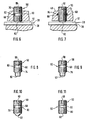
- FIG. 4 is a sectional view of one embodiment of a hold down member having a locking element;
- FIG. 4A is a top view of the hold down member of FIG. 4.
- FIG. 5 is a sectional view of another embodiment of a hold-down member having another locking element;
- FIG. 5A is a top view of the hold down member of FIG. 5.
- FIG. 6 is a sectional view of another embodiment of a hold-down member;
- FIG. 7 is a sectional view of a further embodiment of a hold-down member;
- FIG. 8 is a side view of still another embodiment of a hold-down member;
- FIG. 9 is a side view of another embodiment of a hold-down member;
- FIG. 10 is a side view of another embodiment of a hold-down member;
- FIG. 11 is a side view of yet another embodiment of hold-down member;
- FIG. 12 is an enlarged sectional view of a further embodiment of a hold-down member; and
- FIG. 13 is a partial sectional view taken along line XIII-XIII in FIG. 1.
-
- Referring to Figures 1, 2 and 3, a preferred embodiment of the present invention is illustrated. The
sickle guard 10 comprises twoguards web 16 to form a one-piece multiple (in this case, double) sickle guard. In the illustrated embodiment, the connecting web includes a forward connectingweb 18, also known as a lower trashbar, in front of a knife back 30, and a rearward connectingweb 20 behind the knife back. Eachguard - Each
guard guard body 22 and atine 24 fixed to theguard body 22 at the front end of theguard body 22 in the mowing direction of the cutter assembly (right-hand side as shown in FIGS. 1 and 2). Between eachguard body 22 and itstine 24 is a knife slot 26 (FIG. 2) to receiveknife sections 28 which are secured to a reciprocable knife back 30 byspecial screws 32 and self-lockingnuts 34 as shown. The knife back 30 may be supported in any suitable manner. For example, the guards may have a wear bar as shown in US-A-5 487 259, or may have extra guiding devices mounted to the cutter bar to which the sickle guards are screwed as known in the art. Examples of guards without a wear bar include those used in combines, i.e. harvester-threshers.
Eachguard body 22 is releasably securable via a mountingpad 36 and by means of guard mounting screws to a cutter bar of a mower in a known manner. Eachguard body 22 has a ledger surface 38 (FIG. 2) havinglateral cutting edges 40 facing theknife sections 28. Eachknife section 28 is provided with abottom face 42 and, at the sides, withfacets 44 defining knife section cutting edges as illustrated. Theknife section 28, secured to the knife back 30 are drivable back and forth instroke directions 46 indicated by a doubleheaded arrow (FIG. 1). In this case thefacets 44 are serrated. The facets could, however, alternatively be ground smoothly onto the knife sections or could be formed in any suitable manner known in the art. - An
upper trashbar 48 is fixed between thetines 24 of the twoadjacent guards knife sections 28 as shown. At least one hold-down member 50 extends from theupper trashbar 48 to hold down theknife sections 28 in the direction towards theledger surface 38 of theguard bodies 22. The hold-down member 50 is movable into contact with thetop face 51 of theknife section 28. Preferably, the hold-down member 50 is adjustable relative to theupper trashbar 48 in the direction towards and away from theknife sections 28. More preferably, the hold-down member 50 comprises astud screw 52 having an external thread for engaging a threaded 10mm diameter hole 54 in theupper trashbar 48 in which the hold-down member 50 is received. - In the particular example illustrated in FIGS. 1, 2 and 3, the longitudinal center of the
upper trashbar 48 is widened both in the vertical and in the forward directions to accommodate the threadedhole 54. It is preferred to have a hold-down member only in theupper trashbar 48 as shown, and not also in thetines 24. - Illustrated in FIGS. 4 and 4A is a preferred embodiment of the hold down
member 50 shown in FIGS. 1, 2, and 3. The hold down member comprises thestud screw 52 having an external thread for engaging the threadedhole 54 in theupper trash bar 48, and atop slot 56 by which thestud screw 52 can be adjusted with a screw driver. Adjustment of the hold down member to hold theknife section 28 down is made by rotating thestud screw 52 to the desired position. Overtightening is avoided by placing a thin piece of material, preferably a very thin steel sheet, between the bottom 58 of thestud screw 52 and thetop face 51 of theknife section 28. The sheet is then pulled out sideways and the system adjusted. The play between the bottom 58 and theknife section 28 should be minimal and the steel sheet correspondingly very thin. - A locking
element 60 is provided with thestud screw 52 to prevent inadvertent loosening of the hold downelement 50 once it has been adjusted and set to its operating position. Referring to FIGS. 4 and 4A, alongitudinal slot 62 has been machined into the outer side of thestud screw 52 and astripes 64 of polyamide (such as Nylon®) pressed thereinto. Thestrip 64 extends into or even a little beyond the thread of thestud screw 52. - FIGS. 5 and 5A illustrate another embodiment of a locking
element 60 forstud screw 52. In this embodiment, the lockingelement 60 is in the form of aplug 66 of polyamide pressed into a transverseblind hole 68 provided in the side of thestud screw 52 as shown. - It is understood that materials other than polyamide may be used so long as they provide enough friction in the thread between the
stud screw 52 andstud hole 54 to prevent loosening of thestud screw 52 once it has been set at the desired axial position. - Additional embodiments of the hold-
down member 50 are illustrated in FIGS. 6-11. Each hold-down member 50 is shown as a solidstud screw member hole 54 of thetrashbar 48 as previously described and a bottom 92. FIGS. 6 and 7 showstud screw members trashbar 48 andknife section 28. Adjustment of the stud screw members to hold downknife section 28 is made by rotating the hold-down member to the desired position in a similar manner as described above. - The
stud screw members German Standard DIN 78, Einführung in die DIN-Normen, 1985. FIG. 11, in particular, represents a non-non-standard stud bolt whose lower end has simply been cut transversely to the longitudinal axis and the outer edge rounded a little bit. As withstud screw members 52, these stud screw members preferably have a standard metric thread of M10 and a property class of 10.9 or 12.9 according to German Standard DIN ISO 898 Tl, Einführung in die DIN-Normen, 1985. These materials have good strength and wearresistant properties. It is understood that the hold-down member is not limited to these property classes as any suitable property class can be used. For example, property classes 5.8, 6.8, 8.8, and 9.8 of DIN ISO 393 Tl are also known to be acceptable. - Each of the stud screw members in FIGS. 6 to 11 is shown with a locking
element 60 for preventing inadvertent loosening of the hold-down element once it has been set to its operative position as explained above. In FIGS. 6 and 8-11, the lockingelement 60 comprises a thin layer of material, preferably a synthetic adhesive-like material, that is applied to a ring-like area 82 of the thread of the stud screw. Such locking elements are known in the art and allow removal of the bolt when necessary. - In FIG. 7 another locking element embodiment is shown. A
groove 84 is provided in the wall of the stud screw and aring 86 of locking material embedded therein.Ring 86 projects radially into the path of thestud screw 72 just enough to create the desired amount of friction for the stud screw to stay in place. Any type of suitable locking element, including any type of locking means as known in the art, may be used to lock the hold-down member in place and prevent inadvertent loosening. - In FIGS. 6 and 8, the stud screw member is shown as having a
hexagon socket 88, whereas in FIGS. 7, 9, 10, and 11, ascrew slot 90 is provided for turning the bolt member. Any means for rotating the hold-down member may be used. - Illustrated in FIGS. 12 and 13 is another embodiment of the hold-
down member 50. FIG. 12 shows a hold-down member having aball 94 biased into contact with the top face of theknife section 28. Theball 94 is biased into contact with the top face of theknife section 28 by a biasingmember 96 located within the hold-down member 50 which is formed as a screw member 9 8. The biasingmember 96 comprises a compression spring in the illustrated embodiment. The magnitude of the biasing force can be adjusted by the introduction of a screwdriver into anupper screw slot 100 of thescrew member 98 which can then be rotated relative to theupper trashbar 48. - As shown in FIG. 12, the
screw sleeve 102 of thescrew member 98 extends down below the horizontal diameter of theball 94 to form an abutment edge and thus forms astop 104 which limits the outward movement of theball 94 from thescrew member 98. - This limiting effect is illustrated in FIG. 13, where at the left-hand side in chain-dotted lines the
ball 94 is shown in contact with thetop face 51 of theknife section 28. In contrast, at the right-hand side of FIG. 13, in solid lines, theball 94 is shown in the position which it adopts when theball 94 has overrun thefacet 44 of theknife section 28 by a small amount and then has been prevented from further outward movement by thestop 104. This defines apressure stroke 106 for theball 94. Thispressure stroke 106 can be kept comparatively small.
Claims (9)
- A cutter assembly for a mowing apparatus comprising:at least a first (12) and a second guard (14) laterally spaced from and adjacent one another, each said guard comprising a guard body (22) and a tine (24) secured to said guard body (22);wherein each said guard body (22) has a knife slot (26) between said guard body (22) and said tine (24) to receive a knife section (28) secured to a reciprocating knife back (30);wherein each said guard body (22) has a ledger surface (38) facing said knife section (28), said ledger surface (38) having lateral cutting edges (40);wherein said knife section (28) has knife section cutting edges (cf. 44);at least one connecting web (16;18,20) fixed between adjacent said guard bodies (22, 22) of said adjacent guards (12,14);an upper trashbar (48) fixed between adjacent said tines (24,24) of said adjacent guards (12,14); andhold-down means (50) for holding down said knife section (28) in the direction toward said ledger surface (38) of said guard bodies (22,22), wherein said hold-down means (50) extends from said upper trashbar (48) characterised in that said hold-down means (50) is movable into contact with a top face (51) of said knife section (28),that said hold-down means (50) is adjustable relative to said trashbar (48) in a direction towards and away from said knife section (28),and that said hold-down means (50) has an external thread, and said upper trashbar (48) has a threaded hole (54) to receive said threaded hold-down means (50).
- A cutter assembly according to claim 1 wherein said hold-down means (50) is positioned in the approximate center between said guards (12,14).
- A cutter assembly according to claim 1 or 2, wherein said hold-down means (50) comprises a biasing member (96) for biasing an abutment surface (94) of the hold-down means (50) into contact with the top face (51) of said knife section (28).
- A cutter assembly according to claim 3, wherein said hold-down means (50) comprises a ball member (94) and a biasing member (96) biasing said ball member (94) into contact with said top face (51) of the knife section (28).
- A cutter assembly according to claim 4 wherein said hold-down means (50) further comprises stop means (104) to limit displacement of said ball member (94).
- A cutter assembly according to claim 1 or 2, wherein said hold-down means (50) comprises a stud screw member(52).
- A cutter assembly according to one of claims 1 to 6, wherein said hold-down means (50) further comprises a locking element (60;64;66;82) to prevent inadvertent loosening of said hold-down means (50).
- A cutter assembly according to one of claims 1 to 7, wherein a plurality of hold-down means (50) are disposed in the upper trashbar (48).
- A cutter assembly according to one of claims 1 to 7, wherein a plurality of hold-down means (50) are disposed in the upper trashbar (48) and the tines (24,24).
Applications Claiming Priority (2)
| Application Number | Priority Date | Filing Date | Title |
|---|---|---|---|
| US626777 | 1996-04-02 | ||
| US08/626,777 US5884465A (en) | 1994-09-02 | 1996-04-02 | Cutter assembly for mowing apparatus |
Publications (3)
| Publication Number | Publication Date |
|---|---|
| EP0799561A2 EP0799561A2 (en) | 1997-10-08 |
| EP0799561A3 EP0799561A3 (en) | 1999-04-07 |
| EP0799561B1 true EP0799561B1 (en) | 2001-02-21 |
Family
ID=24511815
Family Applications (1)
| Application Number | Title | Priority Date | Filing Date |
|---|---|---|---|
| EP96115201A Expired - Lifetime EP0799561B1 (en) | 1996-04-02 | 1996-09-21 | Cutter assembly for mowing apparatus |
Country Status (5)
| Country | Link |
|---|---|
| US (1) | US5884465A (en) |
| EP (1) | EP0799561B1 (en) |
| AT (1) | ATE199203T1 (en) |
| CA (1) | CA2179670C (en) |
| DE (1) | DE69611820T2 (en) |
Families Citing this family (14)
| Publication number | Priority date | Publication date | Assignee | Title |
|---|---|---|---|---|
| US8109176B1 (en) * | 2010-04-14 | 2012-02-07 | Kooima Company | Cutting elements with serrated cutting edge |
| USD707726S1 (en) * | 2013-07-10 | 2014-06-24 | Macdon Industries Ltd. | Hold down for a blade of a sickle |
| USD707262S1 (en) * | 2013-07-10 | 2014-06-17 | Macdon Industries Ltd. | Pointed guard for a sickle |
| USD707723S1 (en) * | 2013-07-10 | 2014-06-24 | Macdon Industries Ltd. | Stub guard for a sickle |
| USD707725S1 (en) * | 2013-07-10 | 2014-06-24 | Macdon Industries Ltd. | Hold down for a blade of a sickle |
| USD707724S1 (en) * | 2013-07-10 | 2014-06-24 | Macdon Industries Ltd | Pointed guard for a sickle |
| USD714353S1 (en) * | 2013-12-20 | 2014-09-30 | Macdon Industries Ltd. | Pointed guard for a sickle |
| USD714354S1 (en) * | 2013-12-20 | 2014-09-30 | Macdon Industries Ltd. | Hold down for a blade of a sickle |
| USD714352S1 (en) * | 2013-12-20 | 2014-09-30 | Macdon Industries Ltd. | Stub guard for a sickle |
| USD714355S1 (en) * | 2013-12-20 | 2014-09-30 | Macdon Industries Ltd. | Hold down for a blade of a sickle |
| USD746341S1 (en) * | 2014-09-08 | 2015-12-29 | Macdon Industries Ltd. | Guard for a sickle |
| US11044852B2 (en) | 2019-05-21 | 2021-06-29 | Kooima Ag, Inc. | Agricultural knife with primary and secondary serrations |
| US12478037B2 (en) | 2021-09-17 | 2025-11-25 | Kooima Ag, Inc. | Bale ripper assembly for feed mixer apparatus |
| US12484485B1 (en) | 2022-11-02 | 2025-12-02 | Kooima Ag, Inc. | Cutting element with contoured surface |
Family Cites Families (29)
| Publication number | Priority date | Publication date | Assignee | Title |
|---|---|---|---|---|
| US13433A (en) * | 1855-08-14 | Improvement in gutting apparatus for harvesters | ||
| US379881A (en) * | 1888-03-20 | Cutting apparatus | ||
| US304686A (en) * | 1884-09-09 | Hobace b | ||
| US644040A (en) * | 1899-12-21 | 1900-02-20 | Harrington & Richardson Arms Company | Ejector mechanism for breakdown firearms. |
| US870358A (en) * | 1907-05-23 | 1907-11-05 | David R Griffiths | Mowing-machine. |
| US1945301A (en) * | 1933-07-21 | 1934-01-30 | Wilson Ira Herbert | Guard for mowing and analogous machines |
| US2024309A (en) * | 1934-08-31 | 1935-12-17 | Howard L Smith | Knife stabilizer for mowers and reapers |
| US2484652A (en) * | 1945-06-09 | 1949-10-11 | Case Co J I | Sickle guard |
| US2528659A (en) * | 1946-08-23 | 1950-11-07 | Case Co J I | Cutter bar for harvesters |
| US3099125A (en) * | 1961-06-08 | 1963-07-30 | Massey Ferguson Inc | Mower blade retainer |
| US3298164A (en) * | 1964-06-10 | 1967-01-17 | Elmer S Salyards | Hold down assembly for mowing machines |
| US3401512A (en) * | 1965-07-13 | 1968-09-17 | Int Harvester Co | Reciprocating mower having improved cutting action |
| GB1155464A (en) * | 1965-07-21 | 1969-06-18 | Int Harvester Co | Reciprocating Mower having Transversely Displaced Cutting Means |
| US3314222A (en) * | 1965-09-03 | 1967-04-18 | Int Harvester Co | Adjustable mower sickle guiding and clamping device |
| NL6606404A (en) * | 1966-05-11 | 1967-11-13 | ||
| DE1507170A1 (en) * | 1966-09-22 | 1969-12-18 | Busatis Geb | Mower |
| US3455093A (en) * | 1967-02-27 | 1969-07-15 | Vernon Lloyd Stern | Adjusting holddown clip |
| DE1816316A1 (en) * | 1968-12-21 | 1970-07-02 | Busatis Kg Geb | Mae knife cutting unit |
| US3722196A (en) * | 1971-05-19 | 1973-03-27 | W Templeton | Cutter bar assembly |
| DE2343491A1 (en) * | 1973-08-29 | 1975-03-13 | Busatis Werke Kg | Cutter blade for finger mower - has upwards-slanting contact surface at back of blade with another contact surface at right angles to cutting-plane |
| IT8029065U1 (en) * | 1980-12-05 | 1982-06-05 | Bedogni Erminio | IMPROVED CUTTING BAR. |
| US4894979A (en) * | 1983-05-26 | 1990-01-23 | Hesston Corporation | Sickle guard having adjustable knife section hold-down structure |
| US4553380A (en) * | 1983-12-05 | 1985-11-19 | Hesston Corporation | Adjustable hold down for the sickle of a reciprocating cutter assembly |
| US4519192A (en) * | 1984-03-05 | 1985-05-28 | National-Standard Company | Hold-down sickle guard |
| US4896391A (en) * | 1984-07-09 | 1990-01-30 | Long-Lok Fasteners Corporation | Method of forming a self-locking fastener |
| DD297540A5 (en) * | 1990-09-07 | 1992-01-16 | �������@����������������@��������@�����@����������@���������k�� | CUTTING WORK FOR AGRICULTURAL MACHINERY |
| US5343682A (en) * | 1993-05-21 | 1994-09-06 | Puncochar James C | Adjustable hold down clip |
| US5407312A (en) * | 1993-10-04 | 1995-04-18 | Terrizzi; A. Scott | Fastener system with an entrainable function-facilitating material |
| US5487259A (en) * | 1994-11-30 | 1996-01-30 | Carl Sulberg Gmbh & Co. | Cutter assembly for mowing apparatus |
-
1996
- 1996-04-02 US US08/626,777 patent/US5884465A/en not_active Expired - Fee Related
- 1996-06-21 CA CA002179670A patent/CA2179670C/en not_active Expired - Fee Related
- 1996-09-21 DE DE69611820T patent/DE69611820T2/en not_active Expired - Fee Related
- 1996-09-21 EP EP96115201A patent/EP0799561B1/en not_active Expired - Lifetime
- 1996-09-21 AT AT96115201T patent/ATE199203T1/en not_active IP Right Cessation
Also Published As
| Publication number | Publication date |
|---|---|
| CA2179670C (en) | 2000-08-22 |
| CA2179670A1 (en) | 1997-10-03 |
| EP0799561A2 (en) | 1997-10-08 |
| US5884465A (en) | 1999-03-23 |
| DE69611820D1 (en) | 2001-03-29 |
| DE69611820T2 (en) | 2001-06-07 |
| EP0799561A3 (en) | 1999-04-07 |
| ATE199203T1 (en) | 2001-03-15 |
Similar Documents
| Publication | Publication Date | Title |
|---|---|---|
| CA2179670C (en) | Cutter assembly for mowing apparatus | |
| US5343682A (en) | Adjustable hold down clip | |
| US6543211B1 (en) | Crop harvesting header with angle adjustment of the knife guards | |
| CA1056162A (en) | Cutterbar for a crop harvesting machine | |
| US5979152A (en) | Cutterbar assembly for a reciprocating mower | |
| US5241811A (en) | Sickle covered knifeback | |
| US4909026A (en) | Adjustable stub guard assembly for corp cutting apparatus | |
| EP2713697B1 (en) | Easily serviceable knife arm assembly for a sickle | |
| CA1316356C (en) | Injection molded knife guards | |
| EP2713696B1 (en) | Easily serviceable and removable self-adjudting knife arm and head assembly for a sickle | |
| CA1287223C (en) | Sickle guard having adjustable knife section hold-down structure | |
| US5617712A (en) | Cutter assembly for mowing apparatus | |
| CA2359598C (en) | Crop harvesting header with angle adjustment of the knife guards | |
| CA2141133C (en) | Cutter assembly for mowing apparatus | |
| US20240065145A1 (en) | Mower Knife Device | |
| CA1290946C (en) | Adjustable hold down for the sickle of a reciprocating cutter assembly | |
| US6305153B1 (en) | Cutting member for agricultural mower | |
| CA2223617C (en) | Lifter/cutter guard | |
| EP0208026A2 (en) | Adjustable sickle guard assembly | |
| USRE33546E (en) | Adjustable hold down for a reciprocating cutter assembly | |
| US3952486A (en) | Reciprocating mower shoe attachment | |
| US20050166567A1 (en) | Magnetic attachment of a bed knife in a reel mower assembly | |
| CA2221055A1 (en) | A cutterbar assembly for a reciprocating mower | |
| US3044242A (en) | Reciprocating cutter mounting | |
| EP4104664A1 (en) | A belt-type cutting system for cutting crops in a field |
Legal Events
| Date | Code | Title | Description |
|---|---|---|---|
| PUAI | Public reference made under article 153(3) epc to a published international application that has entered the european phase |
Free format text: ORIGINAL CODE: 0009012 |
|
| AK | Designated contracting states |
Kind code of ref document: A2 Designated state(s): AT BE CH DE LI |
|
| PUAL | Search report despatched |
Free format text: ORIGINAL CODE: 0009013 |
|
| AK | Designated contracting states |
Kind code of ref document: A3 Designated state(s): AT BE CH DE LI |
|
| 17P | Request for examination filed |
Effective date: 19990511 |
|
| 17Q | First examination report despatched |
Effective date: 19990909 |
|
| GRAG | Despatch of communication of intention to grant |
Free format text: ORIGINAL CODE: EPIDOS AGRA |
|
| GRAG | Despatch of communication of intention to grant |
Free format text: ORIGINAL CODE: EPIDOS AGRA |
|
| GRAH | Despatch of communication of intention to grant a patent |
Free format text: ORIGINAL CODE: EPIDOS IGRA |
|
| GRAH | Despatch of communication of intention to grant a patent |
Free format text: ORIGINAL CODE: EPIDOS IGRA |
|
| GRAA | (expected) grant |
Free format text: ORIGINAL CODE: 0009210 |
|
| AK | Designated contracting states |
Kind code of ref document: B1 Designated state(s): AT BE CH DE LI |
|
| PG25 | Lapsed in a contracting state [announced via postgrant information from national office to epo] |
Ref country code: BE Free format text: LAPSE BECAUSE OF FAILURE TO SUBMIT A TRANSLATION OF THE DESCRIPTION OR TO PAY THE FEE WITHIN THE PRESCRIBED TIME-LIMIT Effective date: 20010221 |
|
| REF | Corresponds to: |
Ref document number: 199203 Country of ref document: AT Date of ref document: 20010315 Kind code of ref document: T |
|
| REG | Reference to a national code |
Ref country code: CH Ref legal event code: NV Representative=s name: A. BRAUN, BRAUN, HERITIER, ESCHMANN AG PATENTANWAE Ref country code: CH Ref legal event code: EP |
|
| REF | Corresponds to: |
Ref document number: 69611820 Country of ref document: DE Date of ref document: 20010329 |
|
| EN | Fr: translation not filed | ||
| PGFP | Annual fee paid to national office [announced via postgrant information from national office to epo] |
Ref country code: CH Payment date: 20010921 Year of fee payment: 6 Ref country code: AT Payment date: 20010921 Year of fee payment: 6 |
|
| PGFP | Annual fee paid to national office [announced via postgrant information from national office to epo] |
Ref country code: DE Payment date: 20011009 Year of fee payment: 6 |
|
| PLBE | No opposition filed within time limit |
Free format text: ORIGINAL CODE: 0009261 |
|
| STAA | Information on the status of an ep patent application or granted ep patent |
Free format text: STATUS: NO OPPOSITION FILED WITHIN TIME LIMIT |
|
| 26N | No opposition filed | ||
| PG25 | Lapsed in a contracting state [announced via postgrant information from national office to epo] |
Ref country code: AT Free format text: LAPSE BECAUSE OF NON-PAYMENT OF DUE FEES Effective date: 20020921 |
|
| PG25 | Lapsed in a contracting state [announced via postgrant information from national office to epo] |
Ref country code: LI Free format text: LAPSE BECAUSE OF NON-PAYMENT OF DUE FEES Effective date: 20020930 Ref country code: CH Free format text: LAPSE BECAUSE OF NON-PAYMENT OF DUE FEES Effective date: 20020930 |
|
| PG25 | Lapsed in a contracting state [announced via postgrant information from national office to epo] |
Ref country code: DE Free format text: LAPSE BECAUSE OF NON-PAYMENT OF DUE FEES Effective date: 20030401 |
|
| REG | Reference to a national code |
Ref country code: CH Ref legal event code: PL |