EP0798817A2 - Vorrichtung zum Montieren eines elektrischen Verbinders auf eine Leiterplatte - Google Patents
Vorrichtung zum Montieren eines elektrischen Verbinders auf eine Leiterplatte Download PDFInfo
- Publication number
- EP0798817A2 EP0798817A2 EP97105262A EP97105262A EP0798817A2 EP 0798817 A2 EP0798817 A2 EP 0798817A2 EP 97105262 A EP97105262 A EP 97105262A EP 97105262 A EP97105262 A EP 97105262A EP 0798817 A2 EP0798817 A2 EP 0798817A2
- Authority
- EP
- European Patent Office
- Prior art keywords
- conductive
- pcb
- footer
- aperture
- panel
- Prior art date
- Legal status (The legal status is an assumption and is not a legal conclusion. Google has not performed a legal analysis and makes no representation as to the accuracy of the status listed.)
- Granted
Links
Images
Classifications
-
- H—ELECTRICITY
- H01—ELECTRIC ELEMENTS
- H01R—ELECTRICALLY-CONDUCTIVE CONNECTIONS; STRUCTURAL ASSOCIATIONS OF A PLURALITY OF MUTUALLY-INSULATED ELECTRICAL CONNECTING ELEMENTS; COUPLING DEVICES; CURRENT COLLECTORS
- H01R12/00—Structural associations of a plurality of mutually-insulated electrical connecting elements, specially adapted for printed circuits, e.g. printed circuit boards [PCB], flat or ribbon cables, or like generally planar structures, e.g. terminal strips, terminal blocks; Coupling devices specially adapted for printed circuits, flat or ribbon cables, or like generally planar structures; Terminals specially adapted for contact with, or insertion into, printed circuits, flat or ribbon cables, or like generally planar structures
- H01R12/70—Coupling devices
- H01R12/7005—Guiding, mounting, polarizing or locking means; Extractors
- H01R12/7011—Locking or fixing a connector to a PCB
- H01R12/7047—Locking or fixing a connector to a PCB with a fastener through a screw hole in the coupling device
-
- Y—GENERAL TAGGING OF NEW TECHNOLOGICAL DEVELOPMENTS; GENERAL TAGGING OF CROSS-SECTIONAL TECHNOLOGIES SPANNING OVER SEVERAL SECTIONS OF THE IPC; TECHNICAL SUBJECTS COVERED BY FORMER USPC CROSS-REFERENCE ART COLLECTIONS [XRACs] AND DIGESTS
- Y10—TECHNICAL SUBJECTS COVERED BY FORMER USPC
- Y10S—TECHNICAL SUBJECTS COVERED BY FORMER USPC CROSS-REFERENCE ART COLLECTIONS [XRACs] AND DIGESTS
- Y10S439/00—Electrical connectors
- Y10S439/947—PCB mounted connector with ground terminal
Definitions
- the assembly of this invention includes a PCB having a mounting surface and an opposed surface and a PCB aperture extending between said mounting surface and opposed surface.
- a component of an electrical connector having at least one mounting bracket comprising a footer member and a perpendicular member is positioned on the PCB.
- the footer element has a mounting surface and an opposed surface and an aperture extends through the footer element.
- the footer aperture is generally aligned with said PCB aperture.
- the perpendicular member has a transverse aperture in generally perpendicular relation to the footer aperture.
- a conductive pin extends through said transverse aperture in generally parallel relation to the footer member.
- a fastener means extends axially through the aligned footer aperture and PCB aperture for fixing the connector component to the PCB. Ameans for grounding the conductive pin extending through the conductive aperture of the perpendicular member of the bracket to the PCB is also provided.
- a conductive clip for fixing a component of an electrical connector to a PCB.
- the clip is comprised at a first conductive panel having a fastener means opening and interposed between the mounting sides of the footer member and the PCB.
- a second conductive panel having a fastener means opening and is superimposed over the opposed side of the footer member.
- a resilient conductive pin engagement means is suspended over the second conductive panel. Means are also provided for connecting the resilient conductive pin engagement means to the second conductive panel to the second conductive panel and for connecting the second conductive panel to the first conductive panel.
- the assembly and clip of this invention are, in particular, adapted for use in a method and apparatus for mounting an electrical connector on a PCB which is disclosed in United States Patent Application Serial No. 08/443,789, filed April 8, 1995 which is assigned to the assignee of this application.
- the contents of this Application Serial No. 08/443,789 are incorporated herein by reference.
- Application Serial No. 08/443,789 discloses a method and apparatus in which hold down projections extend upwardly from a tooling plate and the connector is then lowered toward the tooling plate until the hold down apertures are initially engaged with the tooling projection.
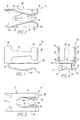
- the conductive clip used in fixing an electrical connector to a PCB in accordance with the present invention is shown generally at numeral 10.
- This conductive clip includes a first resilient conductive panel member shown generally at numeral 12 which includes a transverse base 14 and opposed longitudinal arms 16 and 18 and a central recess 20 positioned between said longitudinal arms. In their relaxed position, the arms 16 and 18 have bowed sections respectively at 22 and 24. Extending upwardly from the base 14 there is a transverse vertical member 26 which connects the first conductive panel to a second horizontal conductive panel shown generally at numeral 28.
- This second conductive panel is comprised of a base 30. Opposed longitudinal arms 32 and 34 form a central recess 36 between the arms.
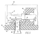
- the clip illustrated in Figs. 1-4 and shown generally at numeral 10 may be used to fix a connector component to a PCB.
- the PCB is shown generally at numeral 58 and has a mounting surface 60 and an opposed surface 62 and a PCB aperture 64 extends transversely between the mounting surface 60 and the opposed surface 62.
- a receptacle shown generally at numeral 66 is positioned on the PCB and is fixed there to a mounting bracket shown generally at numeral 68.
- the mounting bracket has a mounting footer element 70 and a vertical element 72.
- the footer element has a mounting surface 74 and an opposed surface 76 and between these surfaces there is a transverse footer aperture 78.
- the vertical element has a vertical element aperture 80 which is perpendicular to the footer aperture and generally parallel to the footer.
- a conductive pin 82 which may, for example, be connected to another PCB (not shown) extends through the vertical element aperture and generally parallel relation to the footer element and the PCB 58.
- a tubular rivet 84 extends through the aligned footer aperture and PCB aperture and as an upper crimp 86 at its upper terminal end and a lower expansion 88 at its lower terminal end which serves to fix the rivet respectively to the footer element and the PCB. From Fig. 5 it will also be seen that the first conductive panel 12 is interposed between the mounting surfaces of the footer element and the PCB.
- the first conductive panel in this mounted position the first conductive panel is flexed out of its relaxed bowed position to a planar position. It will also be observed that the second conductive panel 28 is superimposed on the opposed surface of footer element. The upper crimp 86 of the tubular member bears against the second panel, and the recess 36 of the second panel allows an opening for the tubular rivet to pass through the footer aperture while at the same time the arms of the second conductive panel are in electrical contact with the tubular rivet. Similarly, the central recess of the first conductive panel allows an opening for the rivet to pass through the PCB aperture, but the longitudinal arms of the first panel are also in electrical contact with the tubular rivet. It will also be observed that the contact surface of the resilient longitudinal arms on the clips are in electrical contact with the conductive pin that extends through the vertical element aperture to ground that conductive pin to the PCB.
Landscapes
- Coupling Device And Connection With Printed Circuit (AREA)
- Multi-Conductor Connections (AREA)
Applications Claiming Priority (2)
| Application Number | Priority Date | Filing Date | Title |
|---|---|---|---|
| US08/622,207 US5762523A (en) | 1996-03-27 | 1996-03-27 | Device for mounting an electrical connector on a printed circuit board |
| US622207 | 1996-03-27 |
Publications (3)
| Publication Number | Publication Date |
|---|---|
| EP0798817A2 true EP0798817A2 (de) | 1997-10-01 |
| EP0798817A3 EP0798817A3 (de) | 1997-12-03 |
| EP0798817B1 EP0798817B1 (de) | 2004-02-25 |
Family
ID=24493313
Family Applications (1)
| Application Number | Title | Priority Date | Filing Date |
|---|---|---|---|
| EP97105262A Expired - Lifetime EP0798817B1 (de) | 1996-03-27 | 1997-03-27 | Vorrichtung zum Montieren eines elektrischen Verbinders auf eine Leiterplatte |
Country Status (4)
| Country | Link |
|---|---|
| US (1) | US5762523A (de) |
| EP (1) | EP0798817B1 (de) |
| KR (1) | KR970068021A (de) |
| DE (1) | DE69727722T2 (de) |
Families Citing this family (3)
| Publication number | Priority date | Publication date | Assignee | Title |
|---|---|---|---|---|
| US5815917A (en) | 1995-05-17 | 1998-10-06 | Berg Technology, Inc. | Method and apparatus for mounting an electrical connector on a printed wiring board |
| US6375472B1 (en) * | 1999-03-11 | 2002-04-23 | 3Com Corporation | Apparatus and method of mounting a bracket apparatus to a circuit board |
| US20050268991A1 (en) * | 2004-06-03 | 2005-12-08 | Enthone Inc. | Corrosion resistance enhancement of tin surfaces |
Citations (7)
| Publication number | Priority date | Publication date | Assignee | Title |
|---|---|---|---|---|
| US3764957A (en) * | 1971-12-17 | 1973-10-09 | Viking Industries | Electrical connector |
| EP0250097A1 (de) * | 1986-06-19 | 1987-12-23 | The Whitaker Corporation | Elektrischer Verbinder für leichte Montage auf einer Leiterplatte und Ösen dafür |
| EP0333386A1 (de) * | 1988-03-15 | 1989-09-20 | The Whitaker Corporation | Abgeschirmter elektrischer Verbinder zur Montage auf gedruckte Schaltungsplatten |
| US4943244A (en) * | 1989-12-26 | 1990-07-24 | Molex Incorporated | Grounding electrical connector |
| US5085589A (en) * | 1991-01-24 | 1992-02-04 | Foxconn International, Inc. | Grounding boardlock for connector |
| US5125853A (en) * | 1991-05-21 | 1992-06-30 | Japan Aviation Electronics Industry, Limited | Electric connector |
| US5230639A (en) * | 1992-06-12 | 1993-07-27 | Amp Incorporated | Top activated eyelet and tool for use therewith |
Family Cites Families (12)
| Publication number | Priority date | Publication date | Assignee | Title |
|---|---|---|---|---|
| US2856593A (en) * | 1954-06-21 | 1958-10-14 | United Shoe Machinery Corp | Connector joint and method of making same |
| US4512618A (en) * | 1983-03-10 | 1985-04-23 | Amp Incorporated | Grounding mating hardware |
| DE3318135A1 (de) * | 1983-05-18 | 1984-11-22 | Erni Elektroapparate Gmbh, 7321 Adelberg | Loetfreie elektrische verbindung |
| US4812130A (en) * | 1985-06-27 | 1989-03-14 | Rca Licensing Corp. | Printed circuit board with mounted terminal |
| US4721470A (en) * | 1987-04-13 | 1988-01-26 | E. I. Du Pont De Nemours And Company | Keys for electrical connectors |
| US4911659A (en) * | 1989-04-21 | 1990-03-27 | Amp Incorporated | Electrical connector and a retention bracket therefor |
| DE8906491U1 (de) * | 1989-05-26 | 1989-07-20 | Rittal-Werk Rudolf Loh Gmbh & Co Kg, 6348 Herborn, De | |
| US5180312A (en) * | 1991-01-23 | 1993-01-19 | Dsc Communications Corporation | Press fit pinless latching shroud |
| US5277618A (en) * | 1991-05-02 | 1994-01-11 | E. I. Du Pont Nemours And Company | Connector having fixing means for mounting on a substrate |
| US5108308A (en) * | 1991-05-31 | 1992-04-28 | Amp Incorporated | Pylon actuated locking eyelet |
| US5183405A (en) * | 1991-12-20 | 1993-02-02 | Amp Incorporated | Grounded electrical connector assembly |
| US5249974A (en) * | 1992-09-15 | 1993-10-05 | Pan-International Industrial Corp. | Multi-contact connector |
-
1996
- 1996-03-27 US US08/622,207 patent/US5762523A/en not_active Expired - Fee Related
-
1997
- 1997-03-26 KR KR1019970010545A patent/KR970068021A/ko not_active Application Discontinuation
- 1997-03-27 DE DE1997627722 patent/DE69727722T2/de not_active Expired - Fee Related
- 1997-03-27 EP EP97105262A patent/EP0798817B1/de not_active Expired - Lifetime
Patent Citations (7)
| Publication number | Priority date | Publication date | Assignee | Title |
|---|---|---|---|---|
| US3764957A (en) * | 1971-12-17 | 1973-10-09 | Viking Industries | Electrical connector |
| EP0250097A1 (de) * | 1986-06-19 | 1987-12-23 | The Whitaker Corporation | Elektrischer Verbinder für leichte Montage auf einer Leiterplatte und Ösen dafür |
| EP0333386A1 (de) * | 1988-03-15 | 1989-09-20 | The Whitaker Corporation | Abgeschirmter elektrischer Verbinder zur Montage auf gedruckte Schaltungsplatten |
| US4943244A (en) * | 1989-12-26 | 1990-07-24 | Molex Incorporated | Grounding electrical connector |
| US5085589A (en) * | 1991-01-24 | 1992-02-04 | Foxconn International, Inc. | Grounding boardlock for connector |
| US5125853A (en) * | 1991-05-21 | 1992-06-30 | Japan Aviation Electronics Industry, Limited | Electric connector |
| US5230639A (en) * | 1992-06-12 | 1993-07-27 | Amp Incorporated | Top activated eyelet and tool for use therewith |
Also Published As
| Publication number | Publication date |
|---|---|
| DE69727722D1 (de) | 2004-04-01 |
| US5762523A (en) | 1998-06-09 |
| DE69727722T2 (de) | 2005-01-13 |
| EP0798817B1 (de) | 2004-02-25 |
| KR970068021A (ko) | 1997-10-13 |
| EP0798817A3 (de) | 1997-12-03 |
Similar Documents
| Publication | Publication Date | Title |
|---|---|---|
| US6511336B1 (en) | Solderless flex termination for motor tab | |
| US4645279A (en) | Chip carrier socket having improved contact terminals | |
| EP0911913B1 (de) | Elektrischer Verbinder | |
| US6538197B1 (en) | Conductive member | |
| CA2245965C (en) | Miniature card edge clip | |
| US4894022A (en) | Solderless surface mount card edge connector | |
| US6386889B1 (en) | Board-to-board electrical connectors | |
| JPH0430718B2 (de) | ||
| EP0373003A2 (de) | Kontakt für auf der Oberfläche montierbare Komponente mit einem lötbaren Teil | |
| US6071131A (en) | Screwless metal circuit board standoff | |
| EP0784358A2 (de) | Haubenartiger Schnapper für elektrischen Verbinder | |
| CN1125538C (zh) | 安装于壳体内用于便携式无线电装置的内置天线 | |
| US6442036B2 (en) | Substrate mount type terminal | |
| WO2000045467A1 (en) | Direct circuit to circuit stored energy connector | |
| US5104339A (en) | Electrical circuit component with latching means for mounting to a circuit substrate | |
| EP0547529A1 (de) | Elektrischer Verbinder mit programmierbarem Ein-/Ausgang | |
| US5762523A (en) | Device for mounting an electrical connector on a printed circuit board | |
| US5873739A (en) | Direct circuit to circuit stored energy connector | |
| US4358172A (en) | Connector for electrical interconnection of circuit board and flat multiconductor cable | |
| US4638406A (en) | Discrete component mounting assembly | |
| US5173842A (en) | Electrical assembly with deformable bridge printed circuit board | |
| US5584707A (en) | Chip socket system | |
| US4423920A (en) | Electrical connecting device | |
| US6685484B2 (en) | Electrical connector and terminal for flat circuitry | |
| JPH05251876A (ja) | 電子部品の取付装置及び取付方法 |
Legal Events
| Date | Code | Title | Description |
|---|---|---|---|
| PUAI | Public reference made under article 153(3) epc to a published international application that has entered the european phase |
Free format text: ORIGINAL CODE: 0009012 |
|
| AK | Designated contracting states |
Kind code of ref document: A2 Designated state(s): DE FR GB |
|
| PUAL | Search report despatched |
Free format text: ORIGINAL CODE: 0009013 |
|
| AK | Designated contracting states |
Kind code of ref document: A3 Designated state(s): DE FR GB |
|
| 17P | Request for examination filed |
Effective date: 19980417 |
|
| 17Q | First examination report despatched |
Effective date: 20021014 |
|
| RIC1 | Information provided on ipc code assigned before grant |
Ipc: 7H 01R 12/20 A |
|
| GRAP | Despatch of communication of intention to grant a patent |
Free format text: ORIGINAL CODE: EPIDOSNIGR1 |
|
| RIC1 | Information provided on ipc code assigned before grant |
Ipc: 7H 01R 12/20 A |
|
| GRAS | Grant fee paid |
Free format text: ORIGINAL CODE: EPIDOSNIGR3 |
|
| RAP1 | Party data changed (applicant data changed or rights of an application transferred) |
Owner name: FCI |
|
| GRAA | (expected) grant |
Free format text: ORIGINAL CODE: 0009210 |
|
| AK | Designated contracting states |
Kind code of ref document: B1 Designated state(s): DE FR GB |
|
| REG | Reference to a national code |
Ref country code: GB Ref legal event code: FG4D |
|
| REF | Corresponds to: |
Ref document number: 69727722 Country of ref document: DE Date of ref document: 20040401 Kind code of ref document: P |
|
| ET | Fr: translation filed | ||
| PLBE | No opposition filed within time limit |
Free format text: ORIGINAL CODE: 0009261 |
|
| STAA | Information on the status of an ep patent application or granted ep patent |
Free format text: STATUS: NO OPPOSITION FILED WITHIN TIME LIMIT |
|
| 26N | No opposition filed |
Effective date: 20041126 |
|
| PGFP | Annual fee paid to national office [announced via postgrant information from national office to epo] |
Ref country code: GB Payment date: 20080211 Year of fee payment: 12 |
|
| PGFP | Annual fee paid to national office [announced via postgrant information from national office to epo] |
Ref country code: FR Payment date: 20080307 Year of fee payment: 12 Ref country code: DE Payment date: 20080331 Year of fee payment: 12 |
|
| GBPC | Gb: european patent ceased through non-payment of renewal fee |
Effective date: 20090327 |
|
| REG | Reference to a national code |
Ref country code: FR Ref legal event code: ST Effective date: 20091130 |
|
| PG25 | Lapsed in a contracting state [announced via postgrant information from national office to epo] |
Ref country code: DE Free format text: LAPSE BECAUSE OF NON-PAYMENT OF DUE FEES Effective date: 20091001 |
|
| PG25 | Lapsed in a contracting state [announced via postgrant information from national office to epo] |
Ref country code: GB Free format text: LAPSE BECAUSE OF NON-PAYMENT OF DUE FEES Effective date: 20090327 Ref country code: FR Free format text: LAPSE BECAUSE OF NON-PAYMENT OF DUE FEES Effective date: 20091123 |